

Page 1

Chapter 1
Chapter 2
Chapter 3
Chapter 4
What is the MM II and How Does It Work?
Section A: What is the MM II?
Section B: How the MM II Works
Section C: Commands: Controlling the Tablet’s Operation
Section D: Changing the Tablet Set Up
Assembly and Installation
Interfacing with the Host
Section A: Hardware Interfaces
RS-232C Interface
TTL Interface
Section B: Baud Rate
Section C: Communication Protocols
Section D: Report Formats
Binary Report Format
ASCII BCD Report Format
Operating Characteristics and Functions
Section A: Controlling the Report Flow
Point Mode
Remote Request Mode
Stream Mode
Switch Stream Mode
Report Rate
Increment Mode
Axis Update Mode
Section B: Setting the Resolution
Resolution, Predefined
Resolution, Definable (Set X, Y Scale)
Section C: Other Functions
Absolute and Relative Coordinates (Delta Mode)
Origin
3
3
4
6
6
7
10
10
11
12
12
12
12
13
15
17
18
18
18
19
19
19
20
24
26
26
27
29
29
30
MM II 1
Page 2

Chapter 5
Chapter 6
Chapter 7
Chapter 8
Appendix A
Appendix B
Appendix C
Appendix D
Reset (to Defaults)
Send Configuration
Tablet Identifier
Transmission Control
Z Commands
Section D: Reserved Commands
Guidelines for Writing a Device Driver
Using the MM II
Checking the Graphics Tablet
Section A: Power/Prox Light
Section B: A Quick Functional Check
Section C: Diagnostic Functions
Code Check
Echo
Self-Test
Send Test Results
Operating Environment, Care and Service
Section A: Operating Environment
Section B: Service
Section C: Care and Cleaning
Section D: Changing the Stylus Refill
Specifications
Changing the Set Up Jumpers
ASCII Conversion Chart
Quick Reference of Commands and Defaults
30
31
33
34
34
36
37
42
43
43
43
44
44
45
45
45
47
47
47
48
49
50
51
54
56
MM II 2
Page 3

MM II 3
Chapter 1: What is the MM II and How Does It Work?
Section A – What is the MM II?
The MM II is a graphics tablet that acts as an input device. It allows for the translation of
graphic information into digital, suitable for computer manipulation.
Steering a computer screen pointer
Selecting locations on menus
Drawing and tracing
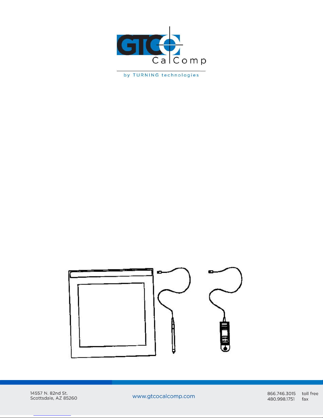
The components required for a functional MM II are:
Tablet
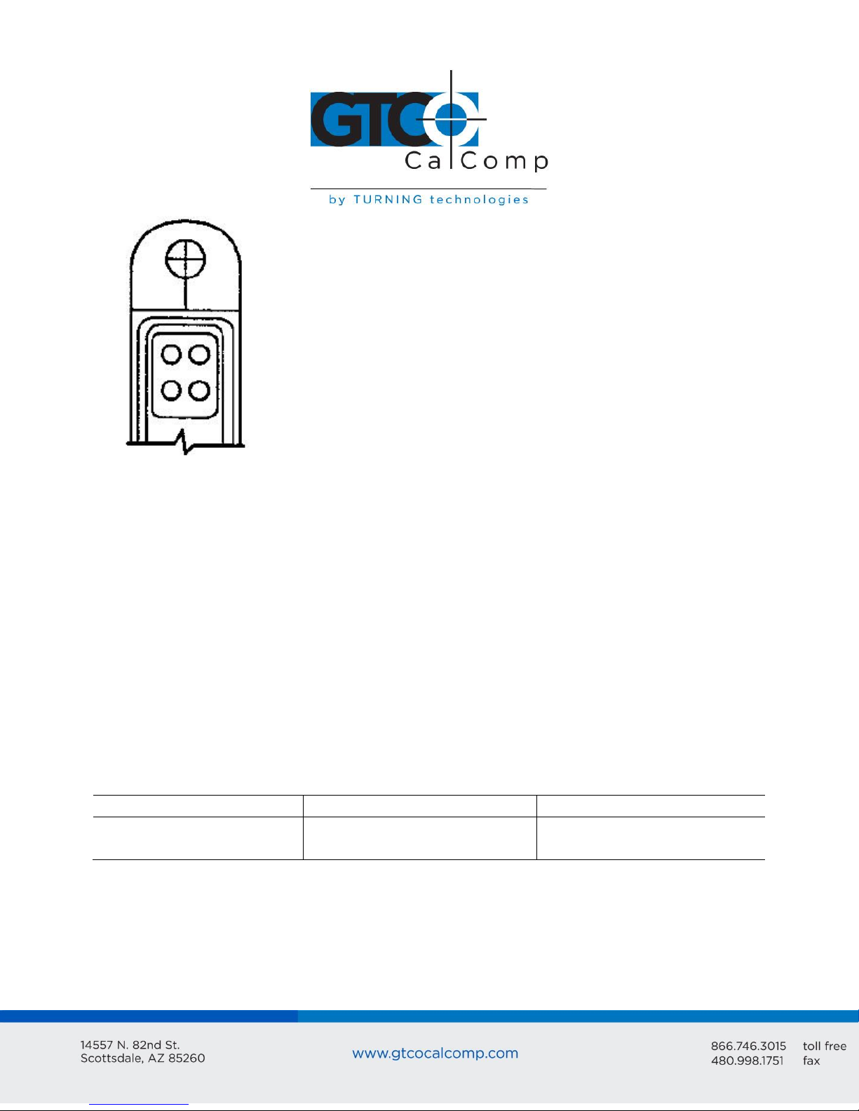
Stylus or cursor
Interface cable
Power source
The tablet is similar to a drawing board. The stylus and cursor are handheld devices that
are used for pointing or drawing on the tablet. The interface cable connects the graphics
tablet to the host (computer).
Page 4
MM II 4
Section B: How the MM II Works
MM II translates the stylus/cursor position on the tablet into digital information and
communicates it to the host. The stylus/cursor position is expressed as an X, Y coordinate
pair. One coordinate pair is a report.
Valid reports can only be collected when the stylus/cursor is in the tablet’s active area and
in proximity:
Active area is an 11.7 inch square area inside the groove on the tablet surface.
Proximity is the maximum distance above the active area that the stylus/cursor can
be held and report a valid position. It’s approximately ½ inches, which means the
stylus/cursor and tablet do not need to be in direct contact with each other to issue
reports. There still can be up to a ½ inch of material (drawings, photos, etc.)
between the tablet and stylus/cursor, allowing it to issue reports.
The active area and proximity, in effect, establish a three-dimensional volume within which
the stylus/cursor can issue valid reports. Reports issued from outside of this volume are
out-of-prox and, therefore, do not represent the current position of the stylus/cursor.
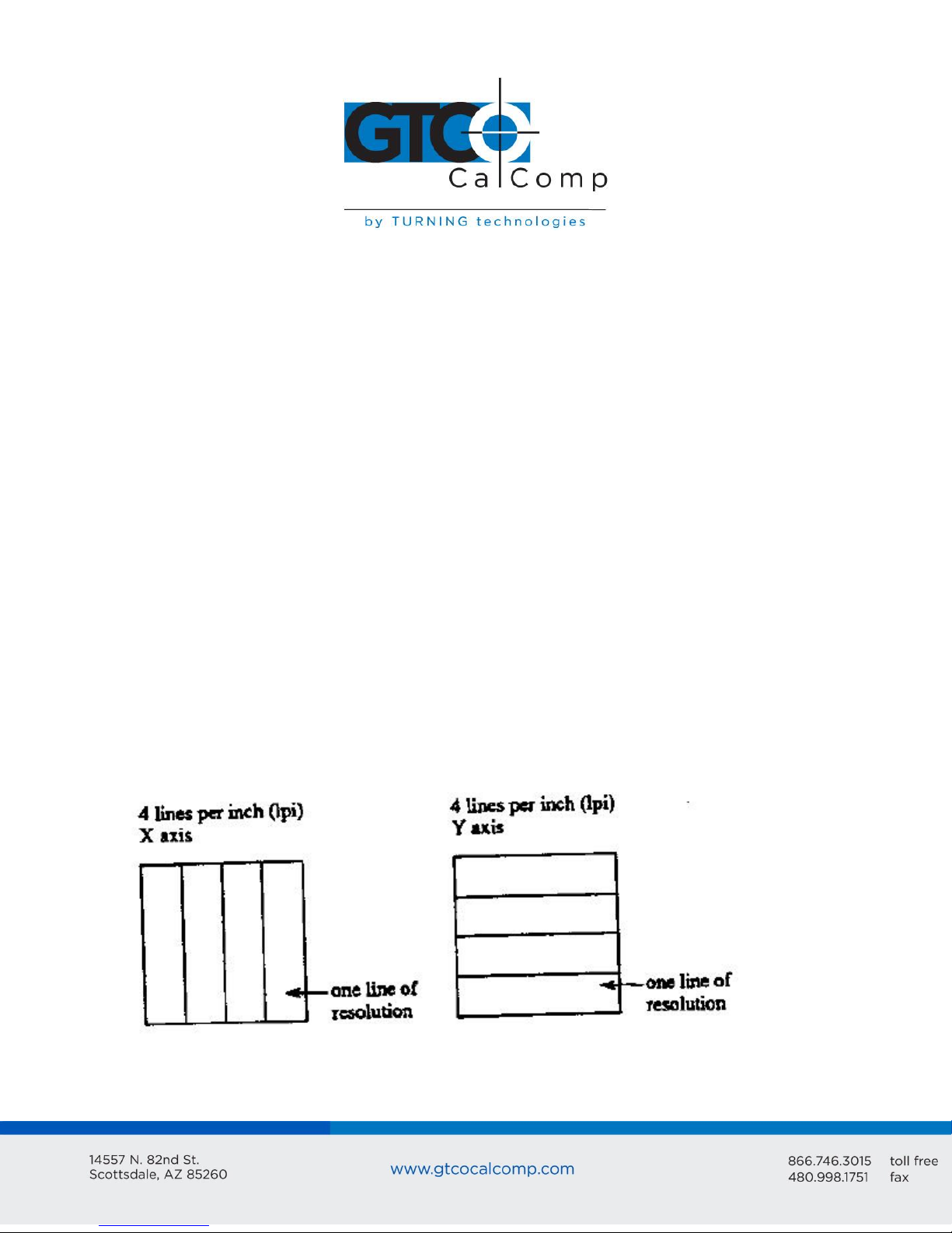
Reports are measured in counts of resolution. Resolution is the fineness of detail that the
tablet can distinguish. It’s expressed in lines per inch (lpi) or lines per millimeter (lpmm).
This is slightly misleading, however. Resolution should be expressed in “bands per …” or
“lanes per …” because these lines have perceivable width at lower resolution settings.
The higher the resolution, e.g. 100 lpi or 200 lpi, the narrower the bands of resolution
become. Eventually, the bands become so narrow that they are easier to conceptualize as
lines of no measurable width.
Page 5
MM II 5
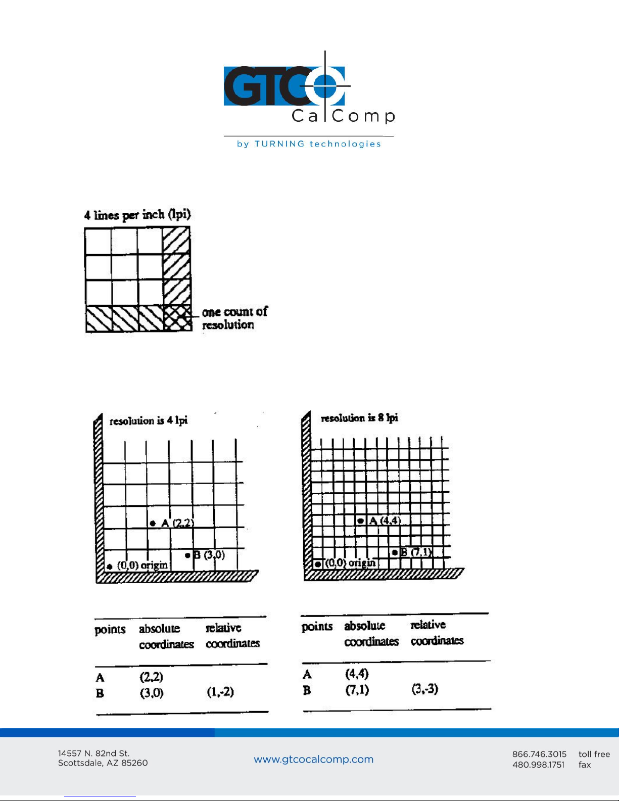
As previously stated, reports are measured in counts of resolution. As shown below, each
square is one count of resolution. The tablet reports the same coordinates for any point
within the square.
With different resolution settings, you can receive different reports for the same tablet
location. In the illustration below, points A and B are the same physical locations on the
tablet, but their coordinates are different because of the resolution setting.
Page 6

MM II 6
Reports are in absolute or relative coordinates. Absolute coordinates are coordinates
measured from the tablet’s origin (0, 0). Relative coordinates are measured relative to the
last report location. In the illustration above, point B is issued after point A. Therefore, in
relative coordinates, point B is measured relative to point A.
The tablet defaults to absolute coordinates. However, you can change to relative
coordinates with the Relative Coordinates command, described in Chapter 4.
Section C – Commands: Controlling the Tablet’s Operation
Control the MM II’s operating characteristics, functions and diagnostics with commands
from the host. This book represents the commands in ASCII. For convenience, an ASCII
conversion chart appears in Appendix C.
The tablet accepts commands from the host at any rate, except as follows:
After turning on the tablet or issue the Reset command, wait approximately ten
milliseconds before sending commands.
Commands that require a tablet response: If you send a command to the tablet that
requires a response, the tablet does so within two milliseconds. Wait until the host
receives the entire response before issuing another command to the tablet.
Section D: Alternative Configurations
The tablet is already set up to operate with a certain:
Baud rate: 9600 or Autobaud
Report format: binary or ASCII BCD
Parity: odd parity or no parity
The standard setup is 9600 baud, binary report format and odd parity. Your unit may be
different.
Change the setup by altering the hardware or with commands from the host. Appendix B
tells you how to change the hardware. Chapter 4 describes the commands. Read the
passages and select the method most appropriate for the situation. Note that the tablet
defaults to the hardware setup each time you turn on the tablet or send the reset
command.
Page 7
Chapter 2: Assembly and Installation
Tablet
Stylus or cursor
Interface cable
Power supply (optional)
Document clips
MM II+ Graphics Tablet User’s Guide
The MM II package should include the following:
To assemble and install MM II:
1. Connect the stylus/cursor to the tablet.
2. Attach the tablet to the host and power source.
3. Turn on the tablet.
4. Attach the document clips. (Optional)
MM II 7
NOTE: Always have the computer and tablet power off when attaching or detaching any
part of the MM II. If the power is on, nothing serious happens to the MM II, but it could
have the potential to corrupt the file being worked on or cause the computer to
malfunction.
Installing MM II Graphics Tablet
1. Plug the stylus/cursor into the modular socket on the right-hand edge of the
tablet.
The cursor and stylus are interchangeable.
Page 8
MM II 8
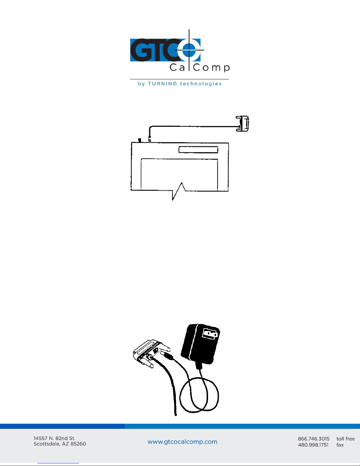
2. Connect the tablet to the host and power source. Plug the interface cable
modular connector into the socket at the top left edge of the tablet.
Plug the interface cable 25-pin D connector into the host communications port.
The tablet can obtain power from the computer or MM II power supply. Never
power the tablet from both simultaneously. Pin 9 and the power supply socket are
connected inside the 25-pin D connector. Therefore, power applied to one, also
exists on the other. Ensure that nothing is attached to the source not in use.
Power from the host must supply +12 VDC at 250 mA, less than 50 mV ripple,
+/- 10% regulation and a rise time less than 100 milliseconds. Once the
tablet is connected to the computer, installation is complete.
Power from the MM II power supply and plug the barrel connector into the
interface cable D connector.
Page 9
MM II 9
Plug the power supply into a standard electrical outlet. Use only an MM II power
supply. Substituting a different power supply could permanently damage the tablet.
3. Turn the tablet on.
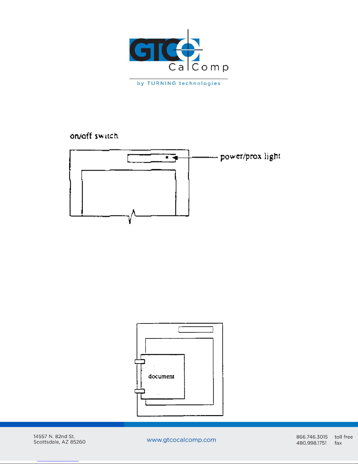
The power light/prox light serves two purposes. First, it notifies that the tablet is on
and receiving power. Second, it is a proximity indicator. The light remains lit when
the stylus/cursor is in-prox. It blinks when the stylus/cursor is out-of-prox. If the
light blinks when the stylus/cursor is in-prox, one of two problems exists. Either, the
stylus/cursor is not connected to the tablet, or it is malfunctioning. (Service
information appears in Chapter 8.)
4. Attach the document clips. (Optional)
MM II comes with document clips. These are to steady documents on the tablet.
Page 10
MM II 10
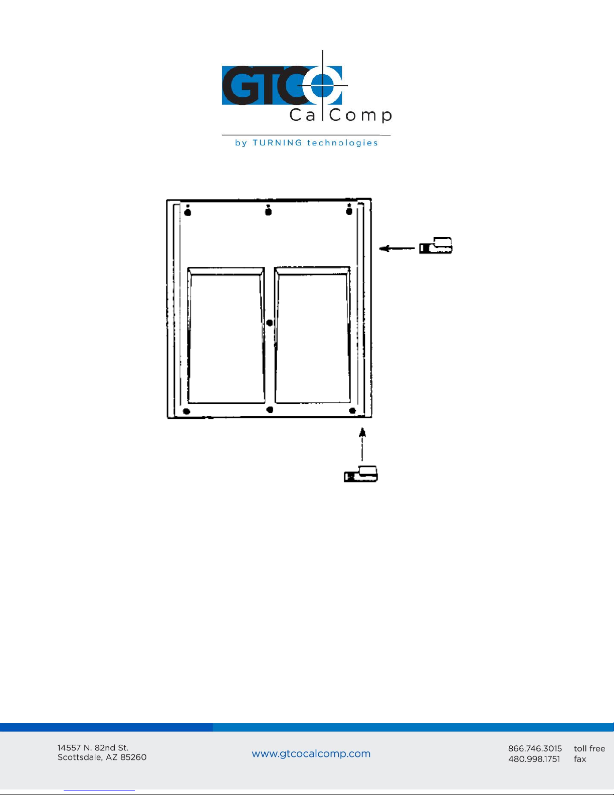
The clips attach to rails on the tablet underside. To attach them, push them straight on or
slide them up from the bottom.
Position the clips where they’re comfortably out of the way. To remove the clips, slide
them to the bottom of the tablet.
Chapter 3: Interfacing with the Host
For successful communication between MM II and its host, they must have the same
hardware interface, baud rate, communications protocol and report format.
Section A: Hardware Interface
The hardware interface consists of one cable terminated with a 25-pin male D connector.
(If the computer requires a different connector, contact your GTCO CalComp by Turning
Technologies representative for information about adapters.)
Page 11
Pin
Wire Name
Description
1
2
3
7
9
11
GND
TXD
RXD
signal ground
+12 VDC
TXD
Protective, frame ground
Transmits data to host (RS-232C only)
Receives data from host (RS-232C or TTL)
Return for data
Power to tablet from host
Transmits data to host (TTL only)
RS-232C Interface
Interchange Voltage
-3V to -12V
+3V to +12V
Binary states
Signal condition
1
Mark
0
Space
The interface accommodates RS-232C and TTL. (Do not use both at the same time.)
RS-232C – CITTL Interface: 25-Pin D Connector Pin Assignments
MM II 11
Pin 9 is for powering the tablet from the host. The host must supply a +12 VDC at 250 mA,
less than 50 mV ripple, +/-10% regulation and a rise time less than 100 milliseconds.
CAUTION:
Never power the tablet from the power supply and host simultaneously.
Pin 9 and the power supply socket are connected inside the 25-pin D connector.
Therefore, power applied to one, also exists on the other. Ensure that nothing is
attached to the source not in use.
RS-232C Interface
The RS-232C lines are configured as DTE (Data Terminal Equipment). The signal levels
comply with standard signal levels for data transmission:
RS-232C Signal Levels
NOTE: The source is the EIA Standard RS-232C: Interface between Data Terminal
Equipment and Data Communication Equipment Employing Serial Binary Data
Interchange, by the Engineering Department of the Electronic Industries Association
(Washington, D.C.: EIA, 1969).
Page 12

MM II 12
TTL Interface
Interchange Voltage
0V to 0.8V
+2.4V to +5V
Binary states
Signal condition
1
Mark
0
Space
TTL Interface
The computer port must provide full duplex, asynchronous, serial communications. The
signal levels for data transmission are:
TTL Signal Levels
Section B: Baud Rate
The MM II is available with 9600 baud or Autobaud. The standard setting is 9600 baud,
unless Autobaud is specifically ordered.
Autobaud automatically matches the tablet baud rate to the host baud rate. The tablet
supports 75 to 19,200 baud. After turning on the tablet, the first character it must receive
from the host is an ASCII space, <SP>. The tablet uses this to identify the host baud rate
and to set its own accordingly.
Section C: Communication Protocols
The MM II communication protocols are:
Number of start bits: 1
Number of data bits: 8
Number of stop bits: 1
Parity: odd or none. (The standard product has odd parity.) To change the parity
setting, refer to Changing the Tablet Setup in Chapter 1.
Section D: Report Formats
The MM II has one of the following report formats:
Binary
ASCII BCD
To change the format, refer to Changing the Tablet Setup in Chapter 1. The reports are in
counts of resolution and not in inches or millimeters.
Page 13
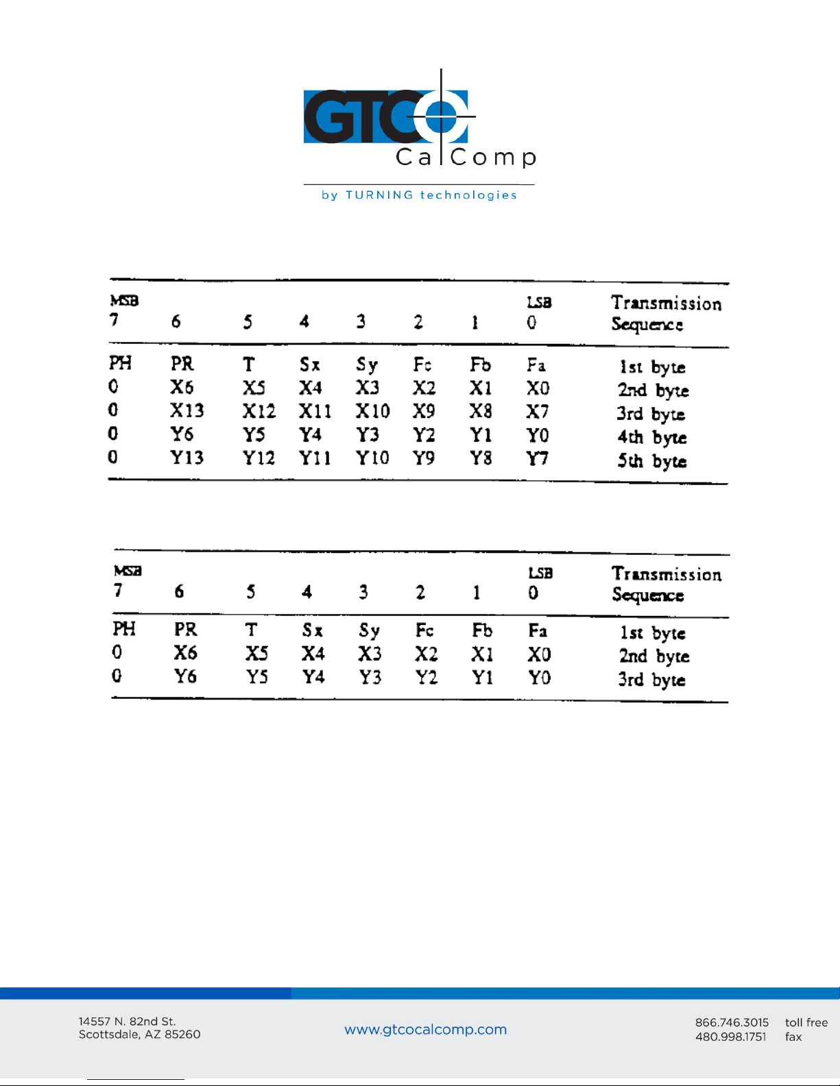
Binary Report Format
Binary Format for Absolute Coordinates
MM II 13
Binary Format for Relative Coordinates
Page 14

Key:
LSB is the least significant bit. MSB is the most significant bit.
Fa, Fb and Fc are the flag bits. They identify the status of the stylus and cursor
buttons:
MM II 14
Page 15
MM II 15
Resolution
Absolute Coordinates
Relative Coordinates
1 to 508 lpi (20 lpmm)
1000 lpi or 40 lpmm
XXXX, YYYY, F<CR><LF>
XXXXX, YYYYY, F<CR><LF>
S0XXX, S0YYY, F<CR><LF>
S00XXX, S00YYY, F<CR><LF>
Sx and Sy are the X and Y coordinate signs. 1 is positive and 0 is negative. In
absolute coordinates, the sign is always positive. In relative coordinates, the sign
can be positive or negative.
T is the Tablet Identifier. Your choice of 1 or 0. Command controlled.
PR is the proximity bit. 0 is in-prox and 1 is out-of-prox.
PH is the phasing bit, which is always 1.
X0, X1, etc. and Y0, Y1, etc. are the X and Y coordinate bits.
ASCII BCD Report Format
The ASCII BCD format depends on the coordinate system and resolution:
Page 16
Key:
X is an X coordinate digit, where each digit is an ASCII character from 0 to 9
“,” is an ASCII comma
Y is a Y coordinate digit, where each digit is an ASCII character from 0 to 9
F is the stylus and cursor flag character, identifying the button status:
MM II 16
Page 17
MM II 17
<CR> is an ASCII carriage return character.
<LF> is an ASCII line feed character.
Chapter 4: Operating Characteristics and Functions
MM II includes a variety of operating characteristics and functions that can be controlled
with commands from the host. For example, define:
Report flow
Tablet resolution
Tablet origin location
The tablet accepts commands from the host at any rate, except in a few situations. These
are listed in Chapter 1, Section C, Commands: Controlling the Tablet’s Operation.
So that the MM II is operable upon arrival at your facility, it is set to predefined default
settings. The unit defaults to these settings each time you turn on the tablet or issue the
Reset command. A summary of the defaults appear in the Reset command section and in
Appendix D.
Page 18
MM II 18
Section A: Controlling the Report Flow
The primary functions that control the report flow are Point, Remote Request, Stream and
Switch Stream modes. The secondary functions are Report Rate, Increment Mode and Axis
Update.
Reports have a proximity bit.
Each report has flag bits. These bits identify the stylus/cursor buttons that were
activated when the report was issued.
Point Mode
In Point Mode, the graphics tablet issues one report when pressing a stylus/cursor button.
If the stylus/cursor is out-of-prox, the last valid report is issued for each button press.
Remote Request Mode
In Remote Request Mode, the tablet issues one report each time the host sends a trigger
command. Issue the mode command once. Thereafter, send only a trigger command for
each report. After initiating Remote Request Mode, the tablet issues the report resulting
from the first trigger within ten milliseconds.
Issue reports with the trigger even if the MM is in Point, Stream or Switch Stream modes.
However, the reverse is not true: pressing a stylus/cursor button when the MM is in
Remote Request Mode does not issue a report.
When the stylus/cursor is out-of-prox, the tablet issues the last valid report each time it
receives a trigger.
Page 19
MM II 19
ASCII command
Report Rate equal to:
Maximum throughput
Maximum throughput +2
Maximum throughput +8
Maximum throughput +32
Q
R
S
T
Stream Mode
In Stream Mode, the graphics tablet issues reports continuously, whether a stylus/cursor
button is pressed or not. The Report Rate, described below, controls the number of
reports issued per second.
If the stylus/cursor is out-of-prox and no buttons have been pressed, the last valid report is
transmitted three times. If a button is pressed, the last valid report is issued continuously.
Switch Stream Mode
In Switch Stream Mode, the graphics tablet issues report continuously while pressing a
stylus/cursor button. The Report Rate, described below, controls the number of reports
issued per second.
If the stylus/cursor is out-of-prox when pressing a button, the last in-prox scanned report is
issued continuously.
Report Rate
The Report Rate function is an adjunct to Stream and Switch Stream modes. Use Report
Rate to define the number of reports the tablet issues each second. Maximum throughput
is the default.
Page 20

Maximum Report Throughput
MM II 20
*Approximate rates. Throughput can vary with coordinate system and resolution setting.
Increment Mode
Command Sequence: <mode command><increment value>
Increment mode is an adjunct to Remote Request, Stream and Switch Stream modes. It is
useful for reducing redundant data output.
In Increment Mode, the tablet sends a report only when the stylus/cursor has traveled a
minimum distance in the X or Y direction. This minimum distance is the increment. It
applies to both axes and is measured in counts (of resolution). Its limits are 0 to 95 counts.
NOTE: When using Increment Mode, we recommend using a resolution setting of 50 lpi or
higher.
How Increment Mode Works
The last report issued becomes the center of an imaginary square. The square’s sides
measure twice the increment value. The stylus/cursor can move anywhere inside the
imaginary square without the tablet issuing a report. When the stylus/cursor touches the
Page 21

MM II 21
square, the increment is met and the tablet transmits a report. This point becomes the
center of a new imaginary square. The process repeats.
The following illustration shows the imaginary square created around a report point. The
increment is five.
The following example shows the reports issued as the stylus/cursor travels across the
tablet. The increment is ten. We have assumed that the first point collected is the origin (0,
0).
Page 22

The points issued are:
desired increment
+32
= increment value in
decimal
= increment value
in hexadecimal
= increment value
in ASCII
10
+32
= 42 decimal
= 2A hexadecimal
= ASCII
MM II 22
How to Use Increment Mode
Send the mode command and then the increment value. The increment value is in counts
(of resolution) and can be a decimal whole number from 0 to 95. (The default is zero.) Add
32 (decimal), a required offset, to the desired increment and then convert the sum into
your preferred number base. For example, if the desired increment value is 10 (decimal),
To disable Increment Mode, set the increment to zero with the ASCII space character (SP).
The length of a count can vary depending on the resolution and measurement system the
tablet is using. Therefore, the increment length can vary:
Page 23

MM II 23
Checking the Increment
You can confirm the increment setting with the zi command. Refer to Z Commands later in
this chapter for additional information.
Combining Increment Mode with Other Modes
Point Mode and Increment Mode: Invalid combination as Point Mode overrides
Increment Mode.
Remote Request Mode and Increment Mode: When the tablet receives a (Remote
Request) trigger from the host, it issues a report. If the increment has not been met
when the tablet receives this trigger, the tablet reissues the last report. If the
increment has been met when the tablet receives this trigger, the tablet advises an
updated report.
Stream Mode and Increment Mode: The tablet issues a report only when the
increment is met. It can issue reports up to the established Report Rate. Also,
pressing a stylus/cursor button reissues the last valid report twice, once when the
button is pressed and then again when it’s released. (The difference between these
reports is the button flag. The flag is set when the button is pressed. It is zero when
the button is released.)
Switch Stream Mode and Increment Mode: If the increment has not been met, the
tablet issues one report when a button is pressed. If the increment has been met
and a button is pressed, the tablet can issue reports up to the established Report
Rate.
Page 24

MM II 24
ASCII command
mode command
update value
G
<SP> to z
Point
Report
Description
1
2
3
4
No
5
6
(0,0)
(10,0)
(10,10)
(20,10)
point is
(30,10)
(30,20)
Reference point, the first point collected in Axis Update Mode.
X update was met. Y was not. Last Y value repeated.
Y update was met. X was not. Last X value repeated.
X update was met. Y was not. Last Y value repeated.
issued between points 4 and 5 because the same report is not issued
consecutively.
X update was met. Y was not. Last Y value repeated.
Y update was met. X was not. Last X value repeated.
Axis Update Mode
Command Sequence: <mode command><update value>
Axis Update Mode is an adjunct to Remote Request, Stream and Switch Stream modes,
particularly useful if using a grid on the tablet and you want reports sectioning the grid
intersection points.
The points issued are:
Page 25

MM II 25
desired increment
+32
= increment value in
decimal
= increment value
in hexadecimal
= increment value
in ASCII
10
+32
= 42 decimal
= 2A hexadecimal
= ASCII
Resolution
Measurement
System
Update Value (in
Counts)
Length of One
Count
Update Length
50 lpi
200 lpi
US
US 5 5
0.02 inches
0.005 inches
0.1 inches
0.025 inches
How to Use Axis Update Mode
Before sending the mode command, place the stylus/cursor on the tablet at one of your
desired grid intersection points. Send the mode command, then the update value. The
update value is in counts (of resolution) and can be a decimal whole number from 0 to 95.
(The default is zero.) Add 32 (decimal), a required offset, to the desired update value and
convert the sum into your preferred number base. For example, if the desired update
value is 10 (decimal).
To disable Axis Update Mode, set the update to zero with the ASCII space character <SP>.
As mentioned above, the update value is in counts. The length of a count can vary
depending on the resolution and measurement system the tablet is using. Therefore, the
update length can vary. For example:
Combining Axis Update Mode with Other Modes
Point Mode and Axis Update Mode: Invalid combination. Point Mode overrides Axis
Update Mode.
Remote Request Mode and Axis Update Mode: When the tablet receives a (Remote
Request) trigger from the host, it issues a report. If the update has not been met
when the tablet receives this trigger, the tablet reissues the last report. If the
update has been met when the tablet receives this trigger, the tablet issues an
updated report.
Stream Mode and Axis Update Mode: The tablet issues a report when the update is
met. It can issue reports up to the established Report Rate. Also, when pressing a
Page 26

MM II 26
ASCII command
Resolution setting of:
1 lpi
2 lpi
4 lpi
100 lpi
200 lpi
10 lpmm (254 lpi)
400 lpi
500 lpi
20 lpmm (508 lpi)
1000 lpi
40 lpmm (1016 lpi)
l (lowercase L)
n
p
d
e
f
g
h
i
j
q
stylus/cursor button, the tablet reissues the last valid report twice, once the button
is pressed and again when it is released. (The difference between these reports is
the button flag. The flag is set when the button is pressed. It is zero when the
button is released.)
Switch Stream Mode and Axis Update Mode: If the update has not been met, the
tablet issues one report when a button is pressed. If the update has been met and
a button is pressed, the tablet can issue reports up to the established Report Rate.
Section B: Setting the Resolution
Resolution is the fineness of detail that the tablet can distinguish. Resolution is expressed
in lines per inch (lpi) or lines per millimeter (lpmm). (A detailed definition of resolution
appears in Chapter 1.) Two resolution functions are available, Predefined Resolution and
Definable Resolution.
Each time the tablet is turned on or issues the Reset command, the tablet defaults to a
resolution of 200 lpi.
Resolution, Predefined
Use these commands to set the tablet to one of the predefined resolutions listed above.
Page 27

MM II 27
Resolution, Definable (Set X, Y Scale)
Command Sequence: <command><X low byte><X high byte><Y low byte><Y high byte>
The purpose of the Definable Resolution function is to let you match the tablet resolution
to the resolution of another two-dimensional device, e.g. a computer screen. With
Definable Resolution:
Define the resolution of each tablet axis, independent of one another.
Clarify the resolution to be any value from 1 to 508 lpi.
Here’s how to use Definable Resolution:
1. Determine the resolution that’s desired for the entire length of the (tablet) axis:
If the other device’s resolution is expressed in “units per…”, such as 37 lines
per inch, multiply that number by the tablet axis length. Example: other
device’s resolution x length of tablet axis = desired axis resolution
37 lpi x 11.7 inches = 432.9 = rounded to 433 … is the desired axis resolution
The other device may have a resolution expressed as the overall axis values,
such as 800 by 1024 pixels.
Page 28

MM II 28
In this case, ensure the length of the corresponding tablet axis divides evenly into the other
device’s resolution. If it does not, the tablet truncates the resolution value to a whole
number.
Example: Matching the MM II to a vertical (portrait) screen with a resolution of 800 (X) by
1024 (Y) pixels:
Other Device’s Resolution / Tablet Axis Length
800 pixels / 11.7 inches = 68.37 … X axis
1024 pixels / 12.7 inches = 87.52 … Y axis
The tablet would truncate these values to 68 and 87. Therefore, round them high to 69 and
88. (This ensures that the entire screen is addressable from the tablet.) Multiply the
rounded values by the tablet axis length to derive the desired resolution for the overall
axis.
69 x 11.7 inches = 807.3 … is the desired X axis resolution
88 x 11.7 inches = 1030 … is the desired Y axis resolution
2. Convert the desired axis resolution to a hexadecimal number.
Example: 808 decimal = 328 hexadecimal
Page 29

MM II 29
Command
X Low Byte
X High Byte
Y Low Byte
Y High Byte
72
28
03
06
04
1030 decimal = 406 hexadecimal
If the number is less from four digits, pack the left side with zeros. For example, 328
becomes 0328; 406 becomes 0406.
Separate the hexadecimal number into two 2-digit parts, the most significant byte
(high byte) and the least significant byte (low byte).
Example:
0328 = 03 high byte 28 low byte
0406 = 04 high byte 06 low byte
3. You’re now ready to send the Definable Resolution command sequence to the
tablet. In the example of 800 by 1024 portrait screen, the command sequence is:
NOTE: To change the resolution of only one axis, send zeros as the other axis’s resolution.
4. To verify the new resolution settings, use the Send Configuration command.
Section C: Other Functions
Absolute and Relative Coordinates (Delta Mode)
These commands change the tablet’s coordinate system. Absolute coordinates are
measured from the tablet’s origin (0,0). Relative coordinates are measured relative to the
last report location. (Refer to Chapter 1 for details.)
The tablet defaults to absolute coordinates.
Page 30

MM II 30
When updating to relative coordinates, the lower left corner of the tablet becomes the
active area origin. Stylus/cursor movement up and to the right is positive. Movement
down and to the left is negative. (You can change the origin location to the upper left
corner with the Origin command. Stylus/cursor movement down and to the right is
positive; up and to the left is negative.)
Also, when the tablet is using relative coordinates, reports issued out-of-prox are zero.
Origin
Use the Origin command to define the location of the tablet’s origin (0, 0). It can be the
lower or upper left corner of the active area. The default is the lower left.
When the origin is in the upper left corner, Y coordinates are positive, not negative. This
departure from the standard Cartesian coordinate system is to aid in the compatibility
between the MM II and terminals with a screen origin in the upper left corner.
Reset (to Defaults)
Use Reset to run the Self-Test diagnostic function and returns the MM to the defaults:
Axis Update: 0, Axis Update Mode off
Coordinate system: absolute
Increment: 0, Increment Mode off
Origin: lower left corner
Page 31

MM II 31
Report Mode: Switch Stream
Report Rate: maximum throughput
Resolution: 500 lpi
Tablet Identifier: 0
After the tablet receives the Reset command, there is a ten millisecond delay before it is
ready to receive further data from the host.
Send Configuration
Send Configuration issues a report to the host that identifies the resolution of each axis.
The report format is one of the following:
Key:
LSB is the least significant bit. MSB is the most significant bit.
Page 32

MM II 32
Fa, Fb and Fc are the flag bits. They identify the status of the stylus and cursor
buttons:
T is the Tablet Identifier, which is 1 or 0.
PR is the proximity bit. 0 is in-prox. 1 is out-of-prox.
b0 through b13 is the maximum X or Y value at the set resolution.
Page 33

MM II 33
The configuration report does not express the resolution in lines per inch or lines per
millimeter. Rather, the resolution is expressed as the total number of counts over the
length of the axis.
Example: Resolution setting is 200 lpi. The X and Y axes are 11.7 inches long. Therefore,
the resolution is 2340 for each axis. The Send Configuration report is:
Tablet Identifier
Use this command to set a bit in the binary report format to a one or a zero. This can be
helpful in a dual-tablet configuration to distinguish between the reports coming from one
tablet versus the other.
Page 34

MM II 34
Transmission Control
The Stop Transmission and Resume Transmission commands act as software gates,
controlling data transmission from the MM II to the host. These commands control the
data flow, regardless of the report collection mode (Stream, Point, etc.). Stop Transmission
and Resume Transmission are equivalents of the protocols XOFF and XON.
Stop Transmission places the graphics tablet on standby. It is useful for systems that do
not constantly use the graphics tablet. End the standby state by sending the Resume
Transmission command.
While on standby, the tablet can buffer up to ten commands, which it executes after
receiving the Resume Transmission command.
If a Stop Transmission is issued while data is being transmitted, no data is lost. The MM II
severs the data transmission at the end of the byte. When a Resume Transmission
command is issued, the tablet resumes operation.
NOTE: The Reset command does not cancel the Stop Transmission command.
Z Commands
Page 35

MM II 35
The z commands include a variety of functions. Some can be used to override the set up
jumpers inside the tablet. To void a z command, send the Reset command or repower the
tablet.
Autobaud: Command overrides set up jumper AA. It changes the default baud rate
to Autobaud, described in Chapter 2. The character <SP> is an ASCII space.
After issuing z<SP>, ensure that the host port is set to the baud rate you want. Only
then can you issue the second <SP>. The tablet responds with an ASCII <ACK> at the
new baud rate.
ASCII BCD report format: Command overrides set up jumper AB. It causes the tablet
to use the ASCII BCD report format.
Binary report format: Command overrides set up jumper AB. It causes the tablet to
use the binary report format/
8 data bits, no parity: Command overrides set up jumper AC. It programs the UART
to use an 8-bit frame: 8 data bits, odd parity. After the command is executed, the
tablet responds with an ASCII <ACK>.
8 data bits, odd parity: Command overrides set up jumper AC. It programs the
UART to use a 9-bit frame: 8 data bits, odd parity. After the command is executed,
the tablet responds with an ASCII <ACK>.
Increment confirmation: Command lets you confirm the current Increment Mode
value. The tablet transmits two ASCII hexadecimal characters followed by an ADCII
carriage return: XX<CR>.
Firmware identification: Command sends a character string to the host that
identifies the tablet firmware version. The string is:
MM2 12x12 Tablet by Summagraphics Firmware Version x.xx<CR>
where x.xx is the firmware version and <CR> is an ASCII carriage return.
Page 36

MM II 36
Transducer identification: Command sends a character string to the host that
identifies which transducer (stylus or cursor) is attached to the tablet. The string is
one of the following:
CSR4<CR> Four button cursor
CSR16<CR> 16-button cursor
STYLUS<CR> Stylus
Section D: Reserved Commands
Do not use the ASCII commands zh, zd or zf or their equivalents. They are reserved for
factory use. If a reserved command is issued by mistake, clear it by repowering the tablet.
Page 37

MM II 37
Chapter 5: Guidelines for Writing a Device Driver
For the computer to make use of the data being sent to it from the tablet, the software
(system or application) must contain a tablet device driver. The driver needs to be written
for your specific MM II configuration.
The device driver is a program that collects and decodes the tablet data.
The driver usually sits between the application and serial interface. The driver should be
able to:
Receive reports and status information from the tablet via the serial interface
Transmit data to the application
Present high level commands from the application that control the tablet
A typical driver consists of four major parts:
Configure Host and Tablet
o Structure the host communications port (port address, baud rate, etc.)
o Shape the tablet (resolution, report mode, etc.)
Report Collection – Interrupt Routines
o Assemble the report: collect the report’s data bytes into an array
o Check for errors
Process Reports from the Tablet
o Decode the report
o Filter reports, if required by the application
o Notify the application, if applicable, that a report is ready to be issued to the
application
Process Errors
o Parity errors
o Short report errors after time-out
o Long report errors
o Missing report errors after time-out
o Host buffer full errors (automatic XON/XOFF support)
Page 38

The following flowcharts are for a MM II in the Bit Pad One configuration.
Configure Host and Tablet
Structure the host communications port (port address, baud rate, etc.)
Shape the tablet (resolution, report mode, etc.)
MM II 38
Page 39

Report Collection – Interrupt Routines
Assemble the report: collect the report’s data bytes into an array
Check for errors
MM II 39
Page 40

Cont.
MM II 40
Page 41

Process Reports from the Tablet
Decode the report
Filter reports, if required by the application
Notify the application, if applicable, that a report is ready to be issued to the
application
MM II 41
Page 42

Chapter 6: Using the MM II
Follow these guidelines to maximize usage of the MM II.
You can tape things down to the tablet, including pictures and drawings. Tape does
not affect the tablet. You can even stack materials up to ½ inch high between the
tablet and stylus/cursor.
After turning on the tablet, wait until it stops calibrating before starting an
application that uses it.
Keep the stylus/cursor in the active area of the tablet and in proximity. Please note
when the stylus/cursor is in proximity, the tablet power light is on. When the
stylus/cursor is out-of-prox, the power light blinks.
Stylus or cursor - which to use? For freehand drawing, the stylus tends to feel more
natural. For tracing, the cursor provides the user with more control and precise
sighting. Also, the cursor has multiple buttons, to which can assign specific
functions.
The cursor and stylus are interchangeable. However, before changing from one to
the other, turn off the tablet. (This allows the tablet’s internal software to re-
initialize for each device.)
Stylus: The stylus has a switch inside the barrel. To activate the switch, press the
stylus tip or button.
MM II 42
Cursor is most accurate when held parallel with the tablet surface. To activate a
cursor button, press it.
When you turn off the computer, turn off the tablet.
The unit is affected by conductive materials. Do not trace through metal or
metallized paper. Do not use metal objects, such as rulers, on the tablet. However,
with the cursor, you can trace through some conductive materials, such as X-rays or
drawings in pencil or conductive ink.
Page 43

MM II 43
Chapter 7: Checking the Graphics Tablet
Section A: Power (and Proximity) Light
The power light on the tablet serves two purposes. First, it notifies when the tablet is on
and receiving power. Second, it is a proximity indicator. The light remains lit when the
stylus/cursor is in-prox. It blinks when the stylus/cursor is out-of-prox. If the light blinks
when the stylus/cursor is in-prox, then the tablet is malfunctioning. Turn it off for an
estimated 10-20 seconds and then turn it back on.
Section B: A Quick Functional Check
Here is a quick functional check that you can perform. Its purpose is to ensure that the
interface is working and that all parts of the tablet active area are being read by the
stylus/cursor.
1. Connect the tablet to a “dumb” terminal. The terminal must be set up to
communicate in full duplex at 9600 baud. If the unit is a Bit Pad One or Two
configurations, the terminal’s data protocol must be a 9-bit frame: odd parity and
eight data bits.
2. On the terminal, enter the command string: zA@. The tablet is now in Stream Mode
sending reports in an ASCII format.
3. Starting at the lower left corner of the tablet, run the stylus/cursor across the
tablet’s active area. You should see reports on the terminal in the following ASCII
format: XXXX, YYYY, F. XXXX, YYYY are the X and Y coordinates. F is the stylus/cursor
flag:
Page 44

MM II 44
The X and Y coordinates should increase as you slide the stylus/cursor up and right, as
shown below.
Section C: Diagnostic Functions
Code Check
Code Check identifies the tablet’s firmware version. It does this by issuing a number called
the checksum, to the host. Each firmware version has a unique checksum.
We recommend that you record the checksum when the unit first arrives and periodically
thereafter. The checksum should always be the same. A change indicates a change in the
firmware.
The checksum is in a six byte format: .#HHHH
HHHH is a hexadecimal number in ASCII. This is the format, regardless of the report
format being used by the tablet.
Page 45

MM II 45
Echo
Use Echo to ensure that the interface between the tablet and host is operating correctly.
The tablet echoes (retransmits) characters back to the host that were sent from the host.
The tablet echoes the characters, one by one, as it receives them. If the interface is
working properly, the sent character matches the echoed character.
Note that character sequences are passed through, not acted upon by the tablet.
Therefore, remote commands issued while Echo is in effect are ignored by the tablet. To
abort the Echo function, issue the Reset command or repower the tablet.
Self-Test
Self-Test checks the following:
Analog circuitry
Stylus/cursor status
Digital circuitry
The tablet performs self-test evaluations each time it is turned on and each time the Reset
or Self-Test command is issued. The test results are stored in the tablet. You can access
them with the Send Test Results command.
Send Test Results
Send Test Results transmits the most recent Self-Test results to the host. The results are
transmitted as one byte:
Page 46

MM II 46
A
C
D
PR
T
Analog circuitry test; pass = 1, fail = 0
Stylus/cursor connection and coil test; pass = 1, fail = 0
Digital circuitry test; pass = 1, fail = 0
Stylus/cursor proximity; in-prox = 1, stylus/cursor out-of-prox = 0
Total test result (based on A,C and D); pass = 1, fail = 0
If the test result is a Hex 8FH or 87H, the tablet passed the tests. Another result means
that the tablet failed.
Page 47

Chapter 8: Operating Environment, Care and Service
Section A: Operating Environment
Operate the MM II within these temperature and humidity ranges:
+45 degrees to +110 degrees Fahrenheit
+7 degrees to +43 degrees Celsius
8% to 80% relative humidity, non-condensing
Acceptable non-operating conditions are:
-45 degrees to +145 degrees Fahrenheit
-43 degrees to +63 degrees Celsius
8% to 80% relative humidity, non-condensing
MM II 47
Extremes in environment can cause degradation of operation. Be careful as extreme
temperatures can occur in some rather surprising places – atop a TV set, in direct sunlight
or in a car on a hot or cold day.
Section B: Service
You should have no problems with the MM II. However, if a problem arises, try one or
more of the following:
Check the hardware connections.
Ensure that the computer is working.
If possible, perform the tests described in Chapter 7.
If applicable, check that the device driver is installed in your system or application
software.
Turn off the computer and tablet. Then turn them on again.
If the tablet continues to malfunction, contact our Customer Service Department at:
GTCO CalComp by Turning Technologies
14557 N. 82nd Street
Scottsdale, AZ 85260
Toll-Free Number: 1.866.746.3015
Page 48

MM II 48
When contacting Customer Service, please have ready the unit serial number. The serial
number is located on the bottom of the tablet. If it is necessary to return the unit,
Customer Service will give you a Return Authorization Number. Write this number on the
outside of the package and on all accompanying paperwork.
NOTE: Please do not ship equipment to GTCO CalComp by Turning Technologies without
obtaining instructions and a Return Authorization Number from the Customer Service
Department.
Section C: Care and Cleaning
The MM II requires minimal care and cleaning. However, the following guidelines are
important:
Disconnect the unit from its power source before cleaning.
Using a soft, damp (not wet), lint-free cloth, wipe the case clean with a mild
detergent solution.
Never disassemble any part of the MM II, except to change the stylus refill.
Never immerse in liquid.
Never bang it around or drop it.
Never scratch or mar the tablet.
Cursor: The transparent part of the cursor that encases the cross hair is called the
paddle. The top surface of the paddle is covered by a special film. It is important to
protect the paddle and film. Do not scratch, mar or separate. To clean the paddle,
wipe with a lint-free cloth dampened with water. Do not use spray cleaner or any
other type of cleaner or solvent.
NOTE: Do not plug MM II connectors into foreign objects. Do not plug foreign objects into
the MM II. Doing so would product unpredictable results and could destroy the tablet.
Page 49

Section D: Changing the Stylus Refill
To change the stylus refill, unscrew the cap and pull the refill straight out.
MM II 49
Insert the new refill until it is firmly seated.
Page 50

Appendix A Specifications
Width
Length
Maximum Height
Weight
16 inches (406 mm)
17 inches (432 mm)
1.3 inches (33 mm)
7 lbs. (3.2 kg) maximum
Standard Accuracy: +/-0.025 inches (1.27 mm) or better
Accuracy is how closely a point’s actual location is determined.
Active Area: 11.7 inches by 11.7 inches (287 mm by 287 mm) approximately
The area of the tablet that senses the stylus/cursor location and where valid reports are
obtained.
Jitter: Stylus or cursor: +/-1 count of resolution
Jitter is the different in values collected by the graphics tablet for the same point (for
example, 200, 201 and 202). Jitter can be caused by electrical noise from environmental
sources or from the tablet’s analog-to-digital conversion circuitry. Noise affects the signal
that identifies a point. Jitter is measured as one unit of the resolution.
Proximity: 0.5 inches (12.7 mm) approximately
Proximity is the maximum distance the stylus/cursor can be held above the active area and
report a valid position.
Resolution: Up to 1016 lpi (40 lpmm)
Resolution is the “fineness” of detail that the tablet can distinguish. Resolution is expressed
in lines per inch (lpi) or lines per millimeter (lpmm).
Physical Description
Approximate physical dimensions:
Power Supply Specifications
The MM II power supply is specified as:
MM II 50
Input: 120 VAC +7%, -13%, 58 to 62 Hz
Output: 5 VDC at 225 mA, less than 50 mV ripple, +/-5% regulation, rise time less
than 100 milliseconds
Operating Specifications
Page 51

MM II 51
Appendix B Changing the Set Up Jumpers
This appendix describes how to change the set up jumpers inside the tablet that control
certain operational defaults:
Baud rate: 9600 or Autobaud
Report format: binary or ASCII BCD
Parity: odd or none
Caution: Performing the procedure described in this appendix is done at your own risk.
We take no responsibility for any damage that could occur.
An alternative to changing the jumpers is to use the Z commands, described in Chapter 4.
In brief, to change the set up jumpers:
1. Disassemble the tablet.
2. Change the jumper caps.
3. Reassemble the tablet.
Disassembling the Tablet
1. Ensure the tablet is turned off and all cables are removed.
2. Turn the tablet upside-down on a clean, smooth surface that will not mar it. The
bottom cover should be facing you.
3. Using a Phillips head screwdriver, remove the three cover screws. (A magnetic
screwdriver is helpful because the screws are recessed.) Lay the screws aside.
Page 52

MM II 52
Notice that the bottom and top covers are held together by tabs on the bottom
cover.
4. Turn the tablet on its side. Tap it gently against the work surface. This shifts the
bottom cover enough to loosen the tabs from their slots at the upper edge.
Page 53

MM II 53
5. Lay the tablet upside down on the work surface. Grasp the side of the tablet that is
still held together. Flex the top cover away from the tabs until they snap loose. Do
the same at the bottom edge.
When the bottom cover is free, remove and set aside. The printed circuit board is now
visible. Do not remove the board from the cover. It protects delicate shielding below.
6. The jumper locations are shown here:
Page 54

Changing Jumpers
Change the jumper caps as you wish.
MM II 54
The jumper caps are black plastic sleeves, open at two ends. To remove a cap, pull straight
up. To attach a cap, push straight down onto the two jumper pins. Both ends of the cap
are the same, so it does not matter which way you attach it.
Page 55

Reassembling the Tablet
1. Ensure that the printed circuit board has not shifted or lifted out of position. It
should be held gently in place by the two posts at the top edge.
MM II 55
2. Hold the bottom cover upside-down over the top cover. Slide the bottom edge of
the bottom cover into the top cover so that the tabs fit into the slots.
3. Snap the bottom cover down against the top cover. The bottom and side tabs
should be seated in the slots.
4. Replace the three cover screws. Gently tighten, but do not over tighten. Too much
pressure can strip the screw threads. Ensure that there is no gap between the top
and bottom covers.
Page 56

Appendix C ASCII Conversion Chart
MM II 56
Page 57

MM II 57
Page 58

MM II 58
Page 59

Appendix D Quick Reference of Commands and Defaults
Command Summary
MM II 59
Page 60

Defaults
Axis Update
Coordinate System
Increment
Origin
Report Mode
Report Rate
Resolution
Tablet Identifier
0, Axis Update Mode off
Absolute
0, Increment Mode off
Lower left corner
Switch Stream
Maximum throughput
500 lpi
0
Baud Rate
Report Format
Parity
9600
Binary
Odd
Standard Product Configuration
MM II 60
Page 61

MM II 61
Corporate Headquarters
14557 N. 82nd Street
Scottsdale, Arizona 85260
Tel: 1-866-746-3015
Support: 1-866-746-3015
Fax: 480-998-1751
Support: 1.866.746.3015
Copyright© 2015 GTCO CalComp by Turning Technologies, Inc.
MM II 1201 is a trademark of GTCO CalComp by Turning Technologies, Inc.
All other products and company names are the trademarks or registered trademarks of
their respective owners.
The information contained in this document is subject to change without notice. GTCO CalComp by
Turning Technologies assumes no responsibility for technical, or editorial errors, or omissions that may
appear in this document, or for the use of this material. Nor does GTCO CalComp by Turning
Technologies make any commitment to update the information contained in this document. This
document contains proprietary information which is protected by copyright. All rights reserved. No part of
this document can be photocopied or reproduced in any form without the prior, written consent of GTCO
CalComp by Turning Technologies, Inc.
 Loading...