

Page 1
CR 1212 1
Chapter 1
Chapter 2
Chapter 3
Chapter 4
What is the CR 1212 and How Does It Work?
Section A: What is the CR 1212?
Section B: How the CR 1212 Works
Section C: Commands: Controlling the Tablet’s Operation
Section D: Alternative Configurations
Assembly and Installation
Interfacing with the Host
Section A: Hardware Interfaces
Section B: Baud Rate
Section C: Communication Protocols
Section D: Report Formats
Operating Characteristics and Functions
Section A: Controlling the Report Flow
Point Mode
Remote Request Mode
Stream Mode
Switch Stream Mode
Report Rate
Increment Mode
Section B: Setting the Resolution
Resolution, Predefined
Resolution, Definable (Set X, Y Scale)
Section C: Other Functions
Bit Pad Configuration
Origin
Relative Coordinates (Delta Mode)
Reset (to Default Operating Characteristics)
Send Configuration
3
3
4
6
6
7
10
10
11
11
12
16
16
17
17
18
18
19
19
22
23
24
27
27
27
28
28
29
Page 2

CR 1212 2
Chapter 5
Chapter 6
Chapter 7
Chapter 8
Appendix A
Appendix B
Tablet Beep
Transmission Control
Section D: Reserved Commands
Guidelines for Writing a Device Driver
Using the CR 1212
Checking the Graphics Tablet
Section A: Tablet Calibration
Section B: Power (and Proximity) Light
Section C: A Quick Functional Check
Section D: Diagnostic Functions
Echo
Self-Test
Operating Environment, Care and Service
Section A: Operating Environment
Section B: Service
Section C: Care and Cleaning
Section D: Changing the Stylus Refill
Specifications
ASCII Conversion Chart
30
31
31
32
37
39
39
39
39
41
41
41
43
43
43
44
45
46
47
Page 3
CR 1212 3
Chapter 1: What is the CR 1212 and How Does It Work?
Section A: What is the CR 1212?
CR 1212 is a graphics tablet that acts as an input device. It allows for the translation of
graphic information into digital, suitable for a digital device such as a computer.
Steering a computer screen pointer
Selecting locations on menus
Drawing and tracing
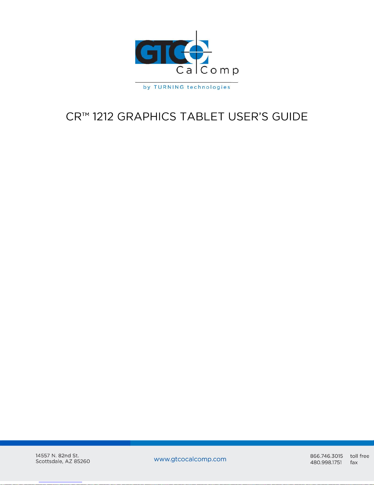
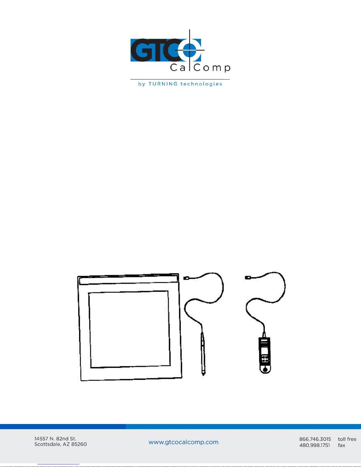
The components required for a functional CR 1212 are:
Tablet
Stylus or cursor
Interface cable
Power source
The tablet is similar to a drawing board. The stylus and cursor are handheld devices that
are used for pointing or drawing on the tablet. The interface cable connects the graphics
tablet to the host (computer).
Page 4
CR 1212 4
Section B: How the CR 1212 Works
CR 1212 translates the stylus/cursor position on the tablet into digital information and
communicates it to the host. The stylus/cursor position is expressed as an X, Y coordinate
pair. One coordinate pair is a report.
Valid reports can only be collected when the stylus/cursor is in the tablet’s active area and
in proximity:
Active area is a 12-inch square area inside the groove on the tablet surface.
Proximity is the maximum distance above the active area that the stylus/cursor can
be held and report a valid position. It’s approximately ½ inches, which means the
stylus/cursor and tablet do not need to be in direct contact with each other to issue
reports. There still can be up to a ½ inch of material (drawings, photos, etc.)
between the tablet and stylus/cursor, allowing it to issue reports.
The active area and proximity, in effect, establish a three-dimensional volume within which
the stylus/cursor can issue valid reports. Reports issued from outside of this volume are
out-of-prox and, therefore, do not represent the current position of the stylus/cursor.
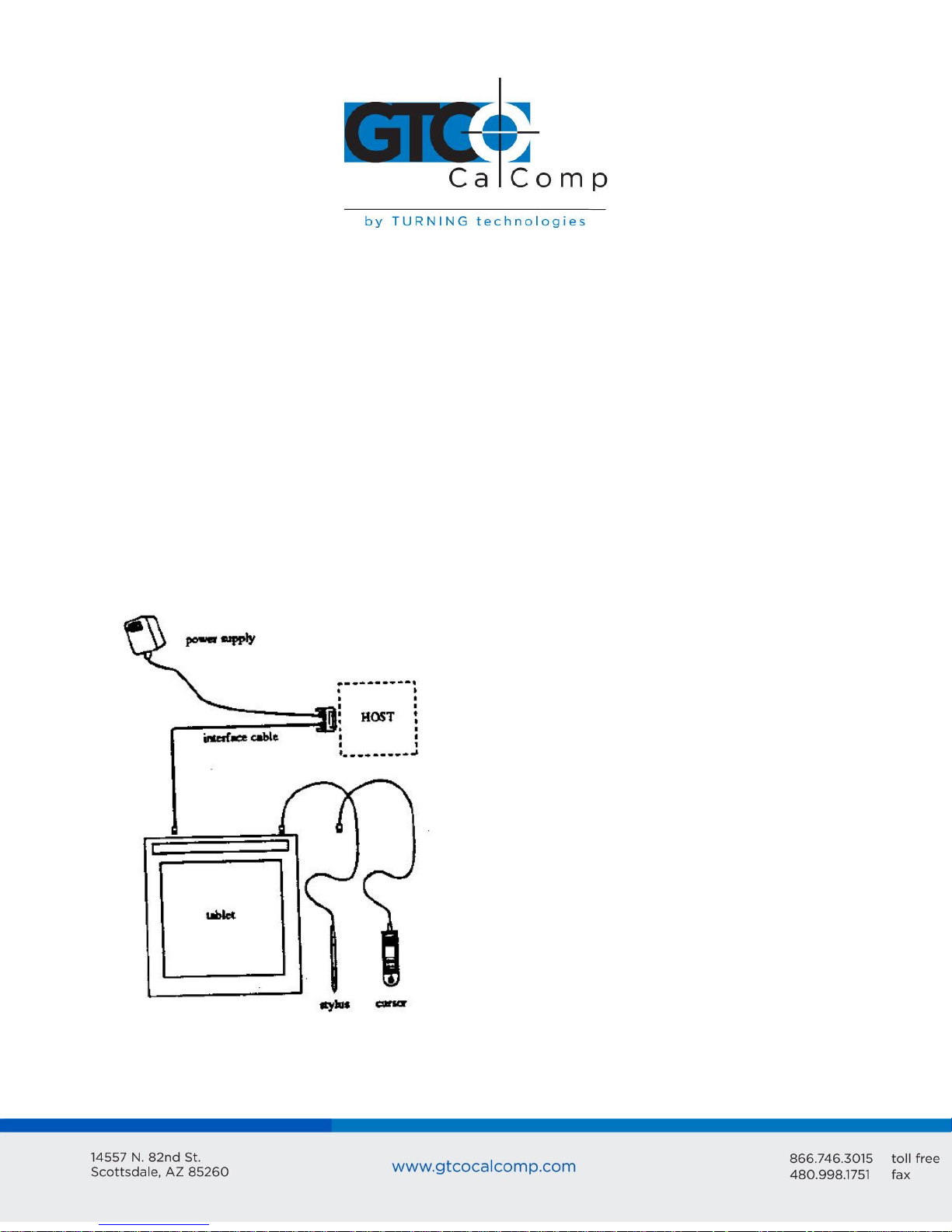
Reports are measured in counts of resolution. Resolution is the fineness of detail that the
tablet can distinguish. It’s expressed in lines per inch (lpi) or lines per millimeter (lpmm).
This is slightly misleading, however. Resolution should be expressed in “bands per …” or
“lanes per …” because these lines have perceivable width at lower resolution settings.
The higher the resolution, e.g. 100 lpi or 200 lpi, the narrower the bands of resolution
become. Eventually, the bands become so narrow that they are easier to conceptualize as
lines of no measurable width.
Page 5
CR 1212 5
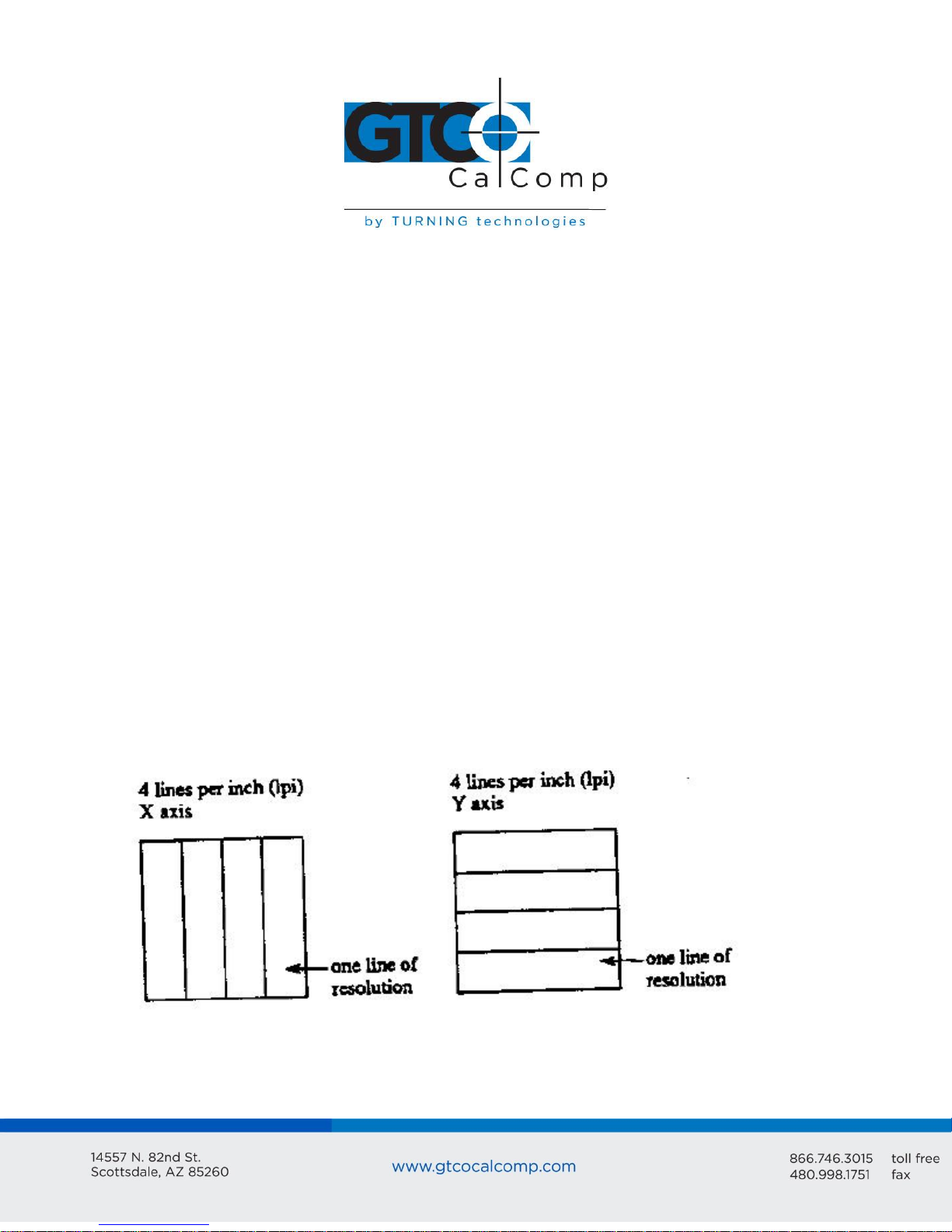
As previously stated, reports are measured in counts of resolution. As shown below, each
square is one count of resolution. The tablet reports the same coordinates for any point
within the square.
With different resolution settings, you can receive different reports for the same tablet
location. In the illustration below, points A and B are the same physical locations on the
tablet, but their coordinates are different because of the resolution setting.
Page 6
CR 1212 6
Reports are in absolute or relative coordinates. Absolute coordinates are coordinates
measured from the tablet’s origin (0, 0). Relative coordinates are measured relative to the
last report location. In the illustration above, point B is issued after point A. Therefore, in
relative coordinates, point B is measured relative to point A.
The tablet defaults to absolute coordinates. However, you can change to relative
coordinates with the Relative Coordinates command, described in Chapter 4.
Section C – Commands: Controlling the Tablet’s Operation
Control the CR 1212’s operating characteristics, functions and diagnostics with commands
from the host. This book represents the commands in ASCII. For convenience, an ASCII
conversion chart appears in Appendix B.
The tablet accepts commands from the host at any rate, except as follows:
After turning on the tablet, wait approximately 300 milliseconds before sending
commands.
Commands that require a tablet response: If you send a command to the tablet that
requires a response, the tablet does so within two milliseconds. Wait until the host
receives the entire response before issuing another command to the tablet.
Definable Resolution (Set X, Y Scale): After issuing the Definable Resolution
command, wait for at least 0.5 milliseconds before issuing another command to the
tablet.
Section D: Alternative Configurations
CR 1212 comes in three operational configurations: Bit Pad One, Bit Pad Two and CR. The
standard configuration is Bit Pad One. The other configurations are special orders.
Page 7
CR 1212 7
Tablet
Stylus or cursor
Interface cable
CR 1212 Graphics Tablet User’s Guide
Chapter 2: Assembly and Installation
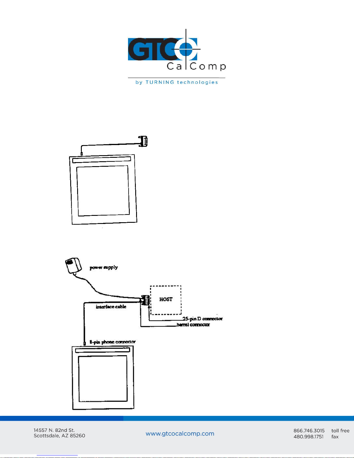
The CR 1212 package should include the following:
To assemble and install CR 1212:
1. Connect the stylus/cursor to the tablet.
2. Attach the tablet to the host and power source.
3. Turn on the tablet.
NOTE: Always have the computer and tablet power off when attaching or detaching any
part of the CR 1212. If the power is on, nothing serious happens to the CR 1212, but it
could have the potential to corrupt the file being worked on or cause the computer to
malfunction.
Installing CR 1212 Graphics Tablet
1. Plug the stylus/cursor into the phone socket on the right-hand edge of the tablet.
Page 8
CR 1212 8
The cursor and stylus are interchangeable. However, before changing from one to the
other, turn off the tablet. (This allows the tablet’s internal software to re-initialize for each
device.)
2. Plug the 8-pin phone connector on the interface cable into the tablet.
3. Connect the 25-pin D connector of the interface cable into the host communications
port.
Page 9

CR 1212 9
4. Plug the power supply barrel connector into the interface cable’s D connector.
5. Plug the power supply into a grounded electrical outlet. Use only a CR 1212 power
supply. Substituting a different power supply could permanently damage the
graphics tablet.
6. Turn the tablet on.
Turn the power (ON/OFF) switch on. The tablet calibrates itself. This takes approximately
three seconds and once the calibration is complete, the tablet beeps.
The power light is lit when the tablet is on. It’s also a proximity indicator that remains lit
when the stylus/cursor is in-prox. It blinks when the stylus/cursor is out-of-prox. If the
light blinks when the stylus/cursor is in-prox, then the tablet is malfunctioning. Turn it off
for 10 or 20 seconds, and then turn it on again. If it fails again, have it serviced.
Page 10
CR 1212 10
Chapter 3: Interfacing with the Host
For successful communication between the CR 1212 and its host, they must have the same
hardware interface, baud rate, communications protocol and report format.
Section A: Hardware Interface
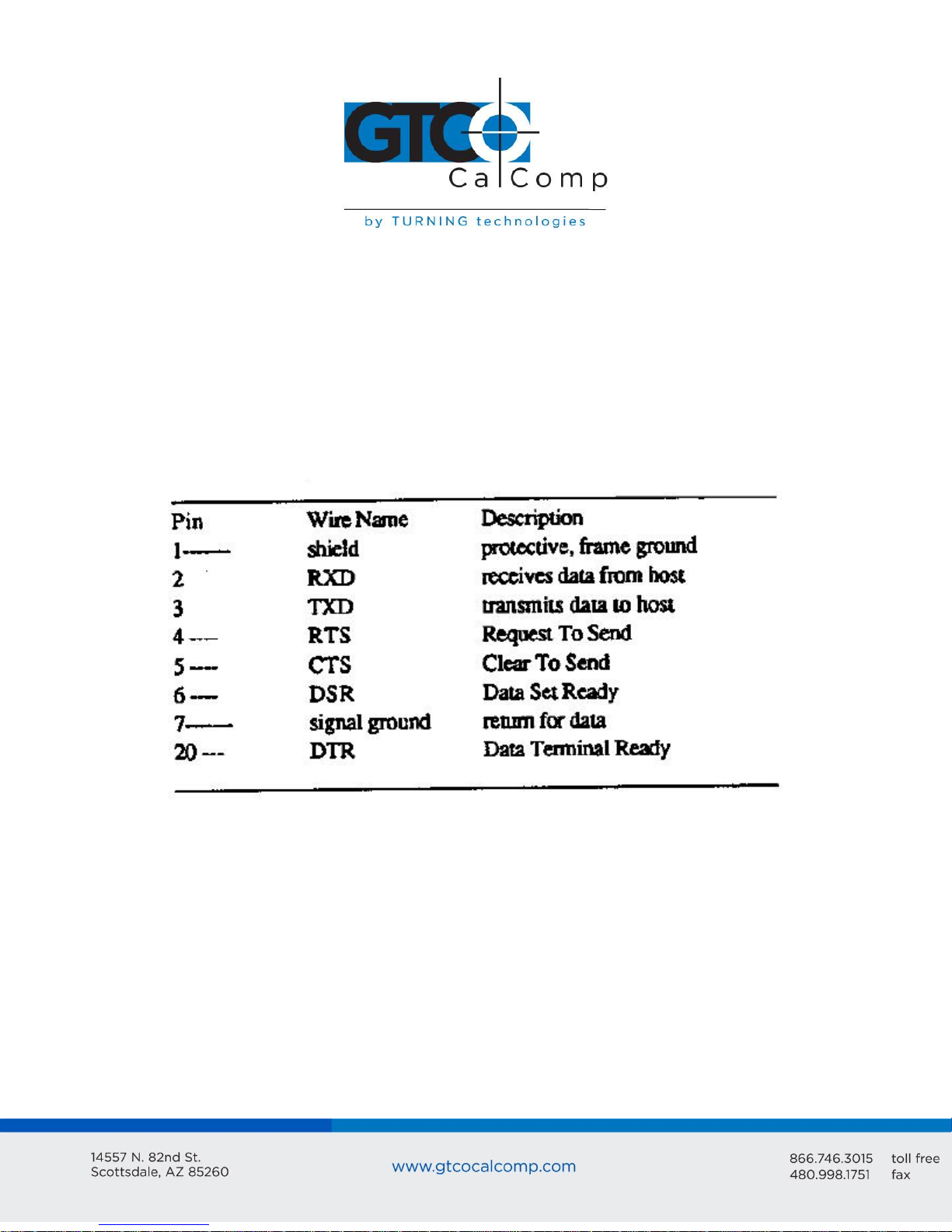
The hardware interface for the CR 1212 is an RS-232C with a 25-pin D connector. The pin
assignments are listed below.
RS-232C Interface: 25-Pin D Connector Pin Assignments
The computer must have an RS-232C communications port terminated with a 25-pin male
D connector that is configured as DTE (Data Terminal Equipment).
NOTE: If the computer has a different connector, contact your GTCO CalComp by Turning
Technologies representative for information about adapter cables.
The CR 1212 complies with standard signal levels for data transmission:
Page 11

CR 1212 11
RS-232C Signal Levels
NOTE: The source is the EIA Standard RS-232C: Interface between Data Terminal
Equipment and Data Communication Equipment Employing Serial Binary Data
Interchange, by the Engineering Department of the Electronics Industries Association
(Washington, D.C.: EIA, 1969).
Section B: Baud Rate
The CR 1212 is available with 9600 baud or Autobaud. The standard setting is 9600 baud,
unless Autobaud is specifically ordered.
Autobaud automatically matches the tablet baud rate to the host baud rate. The tablet
supports 9600, 4800, 2400 and 1200 baud. With Autobaud, you must send an ASCII space
(SP) to the tablet just after starting it. The tablet uses this character to identify the host
baud rate. The tablet then sets its baud rate and issues an ASCII acknowledge (ACK) to the
host.
Section C: Communication Protocols
The CR 1212 communication protocols are:
Page 12
CR 1212 12
Section D: Report Formats
The CR 1212 has one of the following report formats:
Bit Pad One-compatible format (default)
Bit Pad Two-compatible format
CR format (similar to MM packed binary format)
Bit Pad One- or Two-compatible format for Relative Coordinates (Delta Mode)
CR format for Relative Coordinates (similar to MM packed binary format for Delta
Mode)
The report formats are in (packed) binary. The reports are in counts of resolution, not in
inches or millimeters.
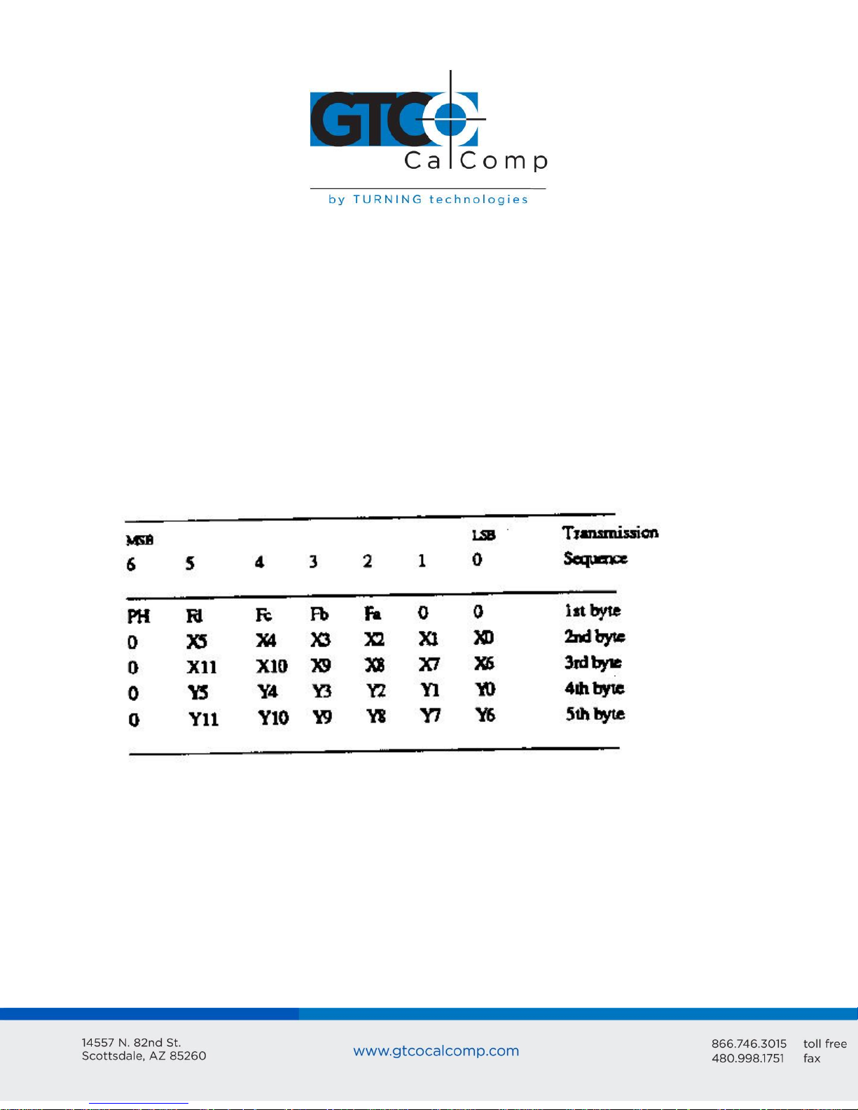
Bit Pad One-Compatible Report Format
Page 13
CR 1212 13
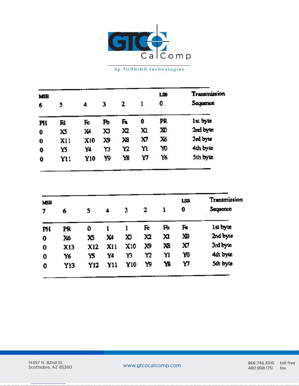
Bit Pad Two-Compatible Report Format
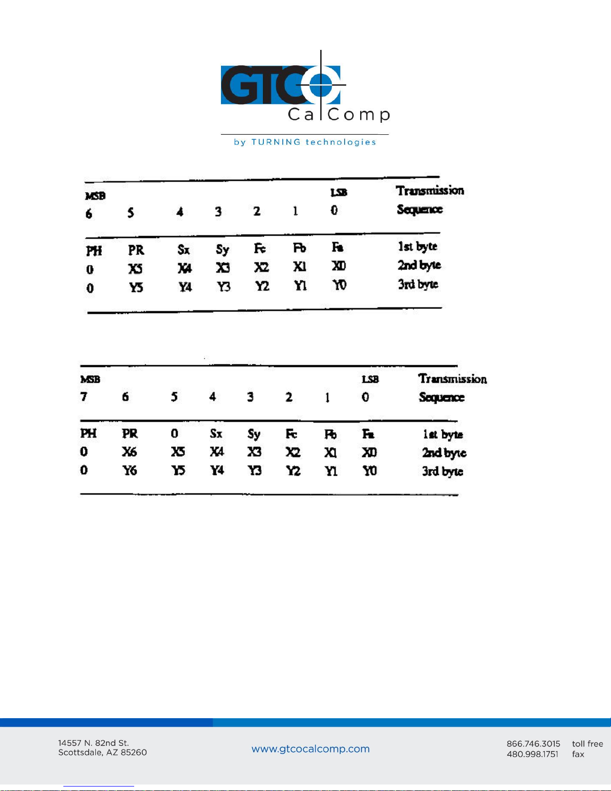
CR Report Format
Page 14
CR 1212 14
Bit Pad One- or Two-compatible format for Relative Coordinates
CR Format for Relative Coordinates
Key:
LSB is the least significant bit. MSB is the most significant bit.
Fa, Fb, Fc and Fd are the flag bits. They identify the status of the stylus tip and
cursor buttons:
Page 15

CR 1212 15
*Output for Bit Pad One or Two configurations using absolute coordinates.
**Output for Bit Pad One or Two configurations using relative coordinates.
Sx and Sy are the X and Y coordinate signs. 1 is positive and 0 is negative.
PR is the proximity bit. 0 is in-prox and 1 is out-of-prox.
PH is the phasing bit, which is always 1.
X0, X1, etc. and Y0, Y1, etc. are the X and Y coordinate bits.
Page 16

CR 1212 16
Chapter 4: Operating Characteristics and Functions
The CR 1212 includes a variety of operating characteristics and functions that can be
controlled with commands from the host. For example, define:
Report flow
Tablet resolution
Tablet origin location
The tablet accepts commands from the host at any rate, except in a few situations. So that
the CR 1212 is operable upon arrival at your facility, it is set to predefined default settings.
The unit defaults to these settings each time you turn on the tablet or issue the Reset
command. A summary of the defaults appear in the Reset command section and in
Appendix B.
Section A: Controlling the Report Flow
The primary functions that control the report flow are Point, Remote Request, Stream and
Switch Stream modes. The secondary functions are Report Rate and Increment Mode.
Bit Pad One configurations: Each time the tablet is turned on or issues the Reset
command, it defaults to Stream Mode.
CR and Bit Pad Two configurations: Each time the tablet is turned on or issues the
Reset command, it defaults to Remote Request Mode.
Bit Pad One reports have no proximity bit. CR and Bit Pad Two reports have a
proximity bit.
Each report has flag bits. These bits identify the stylus/cursor buttons that were
activated when the report was issued.
There is a distinction between scanned reports and issued reports. The tablet reads
the stylus/cursor location 110 times each second. It stores the scanned reports in
an internal buffer. Although the tablet scans continuously, it only issues reports to
the host as dictated by the selected mode, such as Point Mode. The reports sent to
the host are called issue reports.
Page 17

CR 1212 17
A report issued when the stylus/cursor is out-of-prox is always the last in-prox scanned
report. Because the last scanned report may or may not be the last issued report, their
values could be different. You may find this occurring when collecting reports at very slow
rates.
Point Mode
In Point Mode, the graphics tablet issues one report when pressing a stylus/cursor button
and another when releasing it. (The tip of the stylus is its “button”.) If the stylus/cursor is
moved between the time the button is pressed and time it’s released, the reports will be
different. If the stylus/cursor is out-of-prox, the tablet issues the last in-prox scanned
report.
Remote Request Mode
In Remote Request Mode, the tablet issues one report each time the host sends a trigger
command. Issue the mode command once. Thereafter, send only a trigger command for
each report. After initiating Remote Request Mode, the tablet issues the report resulting
from the first trigger within two milliseconds. The tablet can issue subsequent reports up
to 110 rps (reports per second).
When the stylus/cursor is out-of-prox, the tablet issues the last in-prox scanned report
each time it receives a trigger.
Page 18

CR 1212 18
Stream Mode
In Stream Mode, the graphics tablet issues reports continuously, whether a stylus/cursor
button is pressed or not. The Report Rate, described below, controls the number of
reports issued per second.
When moving the stylus/cursor out-of-prox, the tablet issues the last in-prox scanned
report three or four times before it stops transmitting.
Switch Stream Mode
In Switch Stream Mode, the graphics tablet issues report continuously while pressing a
stylus/cursor button. The Report Rate, described below, controls the number of reports
issued per second. When releasing the button, the tablet issues an additional report. This
report is the last scanned report, but its flag bit is 0 (zero).
If the stylus/cursor is out-of-prox when pressing a button, the last in-prox scanned report is
issued continuously.
Page 19

CR 1212 19
Report Rate
The Report Rate function is an adjunct to Stream and Switch Stream modes. Use Report
Rate to define the number of reports the tablet issues each second. Each time the tablet is
turned on or issues a Reset command, the report rate defaults to 110 or 72 rps, depending
on the hardware configuration.
By their very nature, low baud rates limit the report rate. Therefore, follow these
recommendations:
No higher than 36 rps, when using 2400 baud
No higher than 18 rps, when using 1200 baud
Increment Mode
Command Sequence: <mode command><increment value>
Increment mode is an adjunct to Point, Remote Request, Stream and Switch Stream modes.
(It is particularly useful for reducing data output.) In Increment Mode, the unit sends a
report only when the stylus/cursor has traveled a minimum distance in the X or Y direction.
This minimum distance is the increment. It applies to both axes and is measured in counts
(of resolution).
Page 20

CR 1212 20
NOTE: When using Increment Mode, it’s recommended to use a resolution setting of 50 lpi
or higher.
How Increment Mode Works
The last report issued becomes the center of an imaginary square. The square’s sides
measure twice the increment value. The stylus/cursor can move anywhere inside the
imaginary square without the tablet issuing a report. When the stylus/cursor touches the
square, the increment is met and the tablet transmits a report. This point becomes the
center of a new imaginary square. The process repeats.
The following illustration shows the imaginary square created around a report point. The
increment is five.
The following example shows the reports issued as the stylus/cursor travels across the
tablet. The increment is ten. We have assumed that the first point collected is the origin (0,
0).
Page 21

CR 1212 21
desired increment
+32
= increment value in
hexadecimal
= increment value
in ASCII
10
+32
+ 2A hexadecimal
= ASCII
The points issued are:
How to Use Increment Mode
Send the mode command and then the increment value. The increment value is in counts
(of resolution) and can be a decimal whole number from 0 to 90. (The default is zero.) Add
32 (decimal), a required offset, to the desired increment and then convert the sum into
your preferred number base. For example, if the desired increment value is 10 (decimal),
To disable Increment Mode, set the increment to zero with the ASCII space character (SP).
The length of a count can vary depending on the resolution and measurement system the
tablet is using. Therefore, the increment length can vary:
Page 22

CR 1212 22
Combining Increment Mode with Other Modes
Point Mode and Increment Mode: The stylus/cursor location, at the time Increment
Mode is enabled, becomes the center of the initial imaginary square. The tablet
issues one report when pressing a stylus/cursor button and another when releasing
the button. However, reports are updated only when the increment is met.
Remote Request Mode and Increment Mode: When the tablet receives a (Remote
Request) trigger from the host, it issues a report. If the increment has not been met
when the tablet receives this trigger, the tablet reissues the last report. If the
increment has been met when the tablet receives this trigger, the tablet advises an
updated report.
Stream Mode and Increment Mode: The tablet issues a report only when the
increment is met. It can issue reports up to the established Report Rate.
Switch Stream Mode and Increment Mode: If the increment has not been met, the
tablet issues one report when a button is pressed and another when it is released.
If the increment has been met and a button is pressed, the tablet can issue reports
up to the established Report Rate.
Section B: Setting the Resolution
Resolution is the fineness of detail that the tablet can distinguish. Resolution is expressed
in lines per inch (lpi) or lines per millimeter (lpmm). (A detailed definition of resolution
appears in Chapter 1.) Two resolution functions are available, Predefined Resolution and
Definable Resolution.
Each time the tablet is turned on or issues the Reset command, the tablet defaults to a
resolution of 200 lpi.
Page 23

CR 1212 23
Bit Pad One and Two Configurations: The tablet can have a resolution of up to 508 lpi (6096
counts over a 12-inch axis). Bit Pad configurations are restricted to a maximum of 4095
counts. This, in effect, restricts the resolution to 341 lpi (13 lpmm) over a 12-inch axis.
(4095 lpi + 12 inches = 341 lpi) Higher resolutions can be used; however, the active area
shrinks accordingly. For example:
The axis is measured from the active area origin (0, 0). Reports issued from beyond the
axis are clamped to a value of 4095.
Resolution, Predefined
Page 24

CR 1212 24
Use these commands to set the tablet to one of the predefined resolutions listed about.
(Resolution is restricted in Bit Pad One and Two configurations. Refer to Section B: Setting
the Resolution.
Resolution, Definable (Set X, Y Scale)
Command Sequence: <command><X low byte><X high byte><Y low byte><Y high byte>
The purpose of the Definable Resolution function is to let you match the tablet resolution
to the resolution of another two-dimensional device, e.g. a computer screen. With
Definable Resolution:
Define the resolution of each tablet axis, independent of one another.
Specify the resolution to be any value from 10 lpi to 508 lpi. (Resolution is restricted
in Bit Pad One and Two configurations. Refer to Section B: Setting the Resolution.
After issuing the Definable Resolution command, wait at least 0.5 milliseconds before
issuing another command to the tablet.
If Tablet is operating as a Bit Pad One or Bit Pad Two
Here is how to use Definable Resolution:
1. Determine the resolution that’s desired for the entire length of the (tablet) axis:
If the other device’s resolution is expressed in “units per…”, such as 37 lines
per inch, multiply that number by the tablet axis length. Example: other
device’s resolution x length of tablet axis = desired axis resolution
Page 25

CR 1212 25
37 lpi x 12 inches = 444 … is the desired axis resolution
The other device may have a resolution expressed as the overall axis values,
such as 800 by 1024 pixels.
In this case, ensure the length of the corresponding tablet axis divides evenly into the other
device’s resolution. If it does not, the tablet truncates the resolution value to a whole
number.
Example: Matching the CR 1212 to a vertical (portrait) screen with a resolution of 800 (X) by
1024 (Y) pixels:
Other Device’s Resolution / Tablet Axis Length
800 pixels / 12 inches = 66.66 … X axis
1024 pixels / 12 inches = 85.33 … Y axis
The tablet would truncate these values to 66 and 85. Therefore, round them high to 67 and
86. (This ensures that the entire screen is addressable from the tablet.) Multiply the
rounded values by the tablet axis length to derive the desired resolution for the overall
axis.
Page 26

CR 1212 26
Command
X Low Byte
X High Byte
Y Low Byte
Y High Byte
72
24
03
08
04
67 x 12 inches = 804 … is the desired X axis resolution
86 x 12 inches = 1032 … is the desired Y axis resolution
2. Convert the desired axis resolution to a hexadecimal number.
Example: 804 decimal = 324 hexadecimal
1032 decimal = 408 hexadecimal
If the number is less from four digits, pack the left side with zeros. For example, 324
becomes 0324; 408 becomes 0408.
Separate the hexadecimal number into two 2-digit parts, the most significant byte
(high byte) and the least significant byte (low byte).
Example:
0324 = 03 high byte 24 low byte
0408 = 04 high byte 08 low byte
3. You’re now ready to send the Definable Resolution command sequence to the
tablet. In the example of 800 by 1024 portrait screen, the command sequence is:
NOTE: To change the resolution of only one axis, send zeros as the other axis’s resolution.
4. To verify the new resolution settings, use the Send Configuration command.
Page 27

CR 1212 27
Section C: Other Functions
Bit Pad Configuration
If the unit’s hardware configuration is Bit Pad, you can adjust between Bit Pad One and Bit
Pad Two using the commands. (Changing to or from the CR configuration requires a
hardware modification.) Once the configuration is revised; to return to the default, either
send the appropriate command or repower the tablet. The Reset command does not
control the configuration setting.
Origin
Use the Origin command to define the location of the tablet’s origin (0, 0). It can be the
lower or upper left corner of the active area. The default is the lower left.
When the origin is in the upper left corner, Y coordinates are positive, not negative. This
departure from the standard Cartesian coordinate system is to aid in the compatibility
between the CR 1212 and terminals with a screen origin in the upper left corner.
Page 28

CR 1212 28
Relative Coordinates (Delta Mode)
The tablet defaults to an absolute coordinate system. This command changes it to a
relative coordinate system. Absolute coordinates are measured from the tablet’s origin (0,
0). Relative coordinates are measured relative to the last report location. (Refer to
Chapter 1 for details.)
In this operational mode, the active area origin is the lower left corner of the tablet.
Stylus/cursor movement up and to the right is positive. Movement down and to the left is
negative. (You can change the origin location to the upper left corner with the Origin
command. Stylus/cursor movement down to the right is positive; up and to the left is
negative.)
Reset (to Default Operating Characteristics)
Use Reset to return the CR 1212 to the default operating characteristics:
Coordinate system: absolute
Increment: 0, Increment Mode off
Origin: lower left corner
Report Mode: In the Bit Pad One configuration, the mode is Stream. In the
Bit Pad Two or CR configuration, the mode is Remote Request.
Report Rate: 110 or 72 rps (reports per second) depending on hardware
configuration
Resolution: 200 lpi
Tablet Beep: enabled
If the stylus/cursor is out-of-prox when the tablet receives the Reset command, and if it is
still out-of-prox when the tablet issues a report, the X and Y coordinate values are zero.
Page 29

CR 1212 29
Send Configuration
Send Configuration issues a report to the host that identifies the resolution of each axis.
The report format is one of the following:
Bit Pad One or Bit Pad Two Configuration – Report Format
CR Configuration – Report Format
Page 30

CR 1212 30
LSB
MSB
b0
Least significant bit
Most significant bit
Maximum X or Y value at set resolution
Key:
The configuration report does not express the resolution in lines per inch or lines per
millimeter. Rather, the resolution is indicated as the total number of counts over the
length of the axis.
Example: The tablet is the CR configuration. The resolution setting is 200 lpi. The X and Y
axis are 12 inches long. Therefore, the resolution is 2400 for each axis. The Send
Configuration report is:
Tablet Beep
Use this command if you want to disable the tablet beep. To enable it again, issue the
Reset command or repower the tablet.
Page 31

CR 1212 31
Transmission Control
The Stop Transmission and Resume Transmission commands act as software gates,
controlling data transmission from the CR 1212 to the host. These commands control the
data flow, regardless of the report collection mode (stream, Point, etc.).
Stop Transmission and Resume Transmission are equivalents of the transmission protocols
XOFF and XON.
Stop Transmission places the graphics tablet on standby. It is useful for systems that do
not constantly use the graphics tablet. End the standby state by sending the Resume
Transmission command.
NOTE: The Reset command does not cancel the Stop Transmission command.
While the tablet is on standby, it does not buffer reports for subsequent transmission.
However, if you issue Stop Transmission while data is being transmitted, no data is lost.
The CR 1212 severs the data transmission at the end of the report. When you issue the
Resume Transmission command, the tablet continues operation.
While the CR 1212 is on standby, it accepts and executes commands from the host. During
this state, however:
Tablet does not execute the Echo command.
Recommended to limit the number of status commands to one. Status commands
are commands that issue a reply to the host, e.g. Send Configuration. The tablet
issues the reply after it receives XON.
Section D: Reserved Commands
NOTE: Do not use the ASCII commands z, l, n or p or their equivalents. They’re reserved for
factory use. If a reserved command is issued by mistake, clear it by repowering the tablet
or by assigning the Reset command.
Page 32

CR 1212 32
Chapter 5: Guidelines for Writing a Device Driver
For the computer to make use of the data being sent to it from the tablet, the software
(system or application) must contain a tablet device driver. The driver needs to be written
for your specific CR 1212 configuration (Bit Pad One, Bit Pad Two or CR). The device driver
is a program that collects and decodes the tablet data.
The driver usually sits between the application and serial interface. The driver should be
able to:
Receive reports and status information from the tablet via the serial interface
Transmit data to the application
Present high level commands from the application that control the tablet
A typical driver consists of four major parts:
Configure Host and Tablet
o Structure the host communications port (port address, baud rate, etc.)
o Shape the tablet (resolution, report mode, etc.)
Report Collection – Interrupt Routines
o Assemble the report: collect the report’s data bytes into an array
o Check for errors
Process Reports from the Tablet
o Decode the report
o Filter reports, if required by the application
o Notify the application, if applicable, that a report is ready to be issued to the
application
Process Errors
o Parity errors
o Short report errors after time-out
o Long report errors
o Missing report errors after time-out
o Host buffer full errors (automatic XON/XOFF support)
Page 33

CR 1212 33
The following flowcharts are for a CR 1212 in the Bit Pad One configuration.
Configure Host and Tablet
Structure the host communications port (port address, baud rate, etc.)
Shape the tablet (resolution, report mode, etc.)
Page 34

CR 1212 34
Report Collection – Interrupt Routines
Assemble the report: collect the report’s data bytes into an array
Check for errors
Page 35

CR 1212 35
Cont.
Page 36

CR 1212 36
Process Reports from the Tablet
Decode the report
Filter reports, if required by the application
Notify the application, if applicable, that a report is ready to be issued to the
application
Page 37

CR 1212 37
Chapter 6: Using the CR 1212
Follow these guidelines to maximize usage of the CR 1212.
You can tape things down to the tablet, including pictures and drawings. Tape does
not affect the tablet. You can even stack materials up to ½ inch high between the
tablet and stylus/cursor.
After turning on the tablet, wait until it stops calibrating before starting an
application that uses it.
Keep the stylus/cursor in the active area of the tablet and in proximity. Please note
when the stylus/cursor is in proximity, the tablet power light is on. When the
stylus/cursor is out-of-prox, the power light blinks.
Stylus or cursor - which to use? For freehand drawing, the stylus tends to feel more
natural. For tracing, the cursor provides the user with more control and precise
sighting. Also, the cursor has multiple buttons, to which can assign specific
functions in your device driver.
The cursor and stylus are interchangeable. However, before changing from one to
the other, turn off the tablet. (This allows the tablet’s internal software to re-
initialize for each device.)
Stylus: The stylus has a switch inside the barrel. To activate the switch, press the
stylus tip or button.
Hold the stylus above the nose piece, away from the tip. The angle at which you
hold the stylus affects the location reading, so it helps to hold the stylus at the same
angle consistently. The stylus is most accurate when it is perpendicular to the
tablet. However, it functions satisfactorily within 45 degrees of the perpendicular.
Page 38

CR 1212 38
Cursor is most accurate when held parallel with the tablet surface. To activate a
cursor button, press it.
The tablet beeps each time the stylus/cursor button is pressed.
Remember to release the pressure on the stylus/cursor button when you’re done
performing a function.
When you turn off the computer, turn off the tablet.
The unit is affected by conductive materials. Do not trace through metal or
metallized paper. Do not use metal objects, such as rulers, on the tablet. However,
with the cursor, you can trace through some conductive materials, such as X-rays or
drawings in pencil or conductive ink.
Page 39

CR 1212 39
Chapter 7: Checking the Graphics Tablet
Section A: Tablet Calibration
The tablet calibrates each time it’s turned on. The calibration takes less than three seconds
and beeps once completed.
Section B: Power (and Proximity) Light
The power light on the tablet serves two purposes. First, it notifies when the tablet is on
and receiving power. Second, it is a proximity indicator. The light remains lit when the
stylus/cursor is in-prox. It blinks when the stylus/cursor is out-of-prox. If the light blinks
when the stylus/cursor is in-prox, then the tablet is malfunctioning. Turn it off for an
estimated 10-20 seconds and then turn it back on.
Section C: A Quick Functional Check
Here is a quick functional check that you can perform. Its purpose is to ensure that the
interface is working and that all parts of the tablet active area are being read by the
stylus/cursor.
1. Connect the tablet to a “dumb” terminal. The terminal must be set up to
communicate in full duplex at 9600 baud. If the unit is a Bit Pad One or Two
configurations, the terminal’s data protocol must be an 8-bit frame: even parity and
seven data bits. If the unit is a CR configuration, the terminal’s data protocol must
be a 9-bit frame: odd parity and eight data bits.
2. On the terminal, enter the command string: zA@. The tablet is now in Stream Mode
sending reports in an ASCII format.
3. Starting at the lower left corner of the tablet, run the stylus/cursor across the
tablet’s active area. You should see reports on the terminal in the following ASCII
format: F,XXXX,YYYY,P
Page 40

CR 1212 40
The X and Y coordinates should increase as you slide the stylus/cursor up and right, as
shown below.
Page 41

CR 1212 41
Section D: Diagnostic Functions
Echo
Use Echo to ensure that the interface between the tablet and host is operating correctly.
The tablet echoes (retransmits) characters back to the host that were sent from the host.
The tablet echoes the characters, one by one, as it receives them. If the interface is
working properly, the sent character matches the echoed character.
Note that character sequences are passed through, not acted upon by the tablet.
Therefore, remote commands issued while Echo is in effect are ignored by the tablet. To
abort the Echo function, issue the Reset command or repower the tablet.
Self-Test
The Self-Test function tests certain parts of the unit and transmits the results to the host.
The results are transmitted as one byte in one of the following formats:
Bit Pad One and Two Configurations: Self-Test Report
Page 42

CR 1212 42
A
D
PR
CA
T
Analog circuitry test; pass = 1, fail = 0
Digital circuitry test; pass = 1, fail = 0
Stylus/cursor proximity; stylus/cursor in-prox = 1, stylus/cursor out-of-prox = 0
Tablet calibration; pass = 1, fail = 0
Total test result (based on A, D and CA); pass = 1, fail = 0
CR Configuration: Self-Test Report
Bit Pad One and Two configurations: If the test result is a Hex 17 or 1F, or equivalent, the
tablet passed the tests. Any other result means that the tablet failed.
CR configuration: If the test result is a Hex 9F or 97, or equivalent, the tablet passed the
tests. Any other result means that the tablet failed.
Page 43

CR 1212 43
Chapter 8: Operating Environment, Care and Service
Section A: Operating Environment
Operate the CR 1212 within these temperature and humidity ranges:
+45 degrees to +110 degrees Fahrenheit
+7 degrees to +43 degrees Celsius
8% to 80% relative humidity, non-condensing
Acceptable non-operating conditions are:
-45 degrees to +145 degrees Fahrenheit
-43 degrees to +63 degrees Celsius
8% to 80% relative humidity, non-condensing
Extremes in environment can cause degradation of operation. Be careful as extreme
temperatures can occur in some rather surprising places – atop a TV set, in direct sunlight
or in a car on a hot or cold day.
Section B: Service
You should have no problems with the CR 1212. However, if a problem arises, try one or
more of the following:
Check the hardware connections.
Ensure that the computer is working.
If possible, perform the tests described in Chapter 7.
If applicable, check that the device driver is installed in your system or application
software.
Turn off the computer and tablet. Then turn them on again.
If the tablet continues to malfunction, contact our Customer Service Department at:
GTCO CalComp by Turning Technologies
14557 N. 82nd Street
Scottsdale, AZ 85260
Toll-Free Number: 1.866.746.3015
Page 44

CR 1212 44
When contacting Customer Service, please have ready the unit serial number. The serial
number is located on the bottom of the tablet. If it is necessary to return the unit,
Customer Service will give you a Return Authorization Number. Write this number on the
outside of the package and on all accompanying paperwork.
NOTE: Please do not ship equipment to GTCO CalComp by Turning Technologies without
obtaining instructions and a Return Authorization Number from the Customer Service
Department.
Section C: Care and Cleaning
The CR 1212 requires minimal care and cleaning. However, the following guidelines are
important:
Disconnect the unit from its power source before cleaning.
Using a soft, damp (not wet), lint-free cloth, wipe the case clean with a mild
detergent solution.
Never disassemble any part of the CR 1212, except to change the stylus refill.
Never immerse in liquid.
Never bang it around or drop it.
Never scratch or mar the tablet.
Cursor: The transparent part of the cursor that encases the cross hair is called the
paddle. The top surface of the paddle is covered by a special film. It is important to
protect the paddle and film. Do not scratch, mar or separate. To clean the paddle,
wipe with a lint-free cloth dampened with water. Do not use spray cleaner or any
other type of cleaner or solvent.
NOTE: Do not plug CR 1212 connectors into foreign objects. Do not plug foreign objects
into the CR 1212. Doing so would product unpredictable results and could destroy the
tablet.
Page 45

CR 1212 45
Section D: Changing the Stylus Refill
To change the stylus refill, grasp the refill by the tip and pull straight out. Since the tip is
small and slippery, you will probably not be able to pull it out with your bare fingers. We
recommend using needle nose pliers or two coins.
Insert the new refill until it is firmly seated.
Page 46

CR 1212 46
Width
Length
Maximum Height
Weight
16 inches (406 mm)
17 inches (432 mm)
1.3 inches (33 mm)
7 lbs. (3.2 kg) maximum
Standard Accuracy: +/-0.050 inches (1.27 mm) or better
Accuracy is how closely a point’s actual location is determined.
Active Area: 12 inches by 12 inches (305 mm by 305 mm) approximately
The area of the tablet that senses the stylus/cursor location and where valid reports are
obtained.
Jitter: Stylus or cursor: +/-1 count of resolution
Jitter is the different in values collected by the graphics tablet for the same point (for
example, 200, 201 and 202). Jitter can be caused by electrical noise from environmental
sources or from the tablet’s analog-to-digital conversion circuitry. Noise affects the signal
that identifies a point. Jitter is measured as one unit of the resolution.
Proximity: 0.5 inches (12.7 mm) approximately
Proximity is the maximum distance the stylus/cursor can be held above the active area and
report a valid position.
Resolution: Up to 508 lpi (lines per inch)
Resolution is the “fineness” of detail that the tablet can distinguish. Resolution is expressed
in lines per inch (lpi) or lines per millimeter (lpmm).
Appendix A Specifications
Physical Description
Approximate physical dimensions:
Power Supply Specifications
The CR 1212 power supply for the RS-232C configuration is specified as:
Input: 120 VAC +7%, -13%, 58 to 62 Hz
Output: 5 VDC at 225 mA, less than 50 mV ripple, +/-5% regulation, rise time less
than 100 milliseconds
Operating Specifications
Page 47

CR 1212 47
Appendix B ASCII Conversion Chart
Page 48

CR 1212 48
Page 49

CR 1212 49
Page 50

CR 1212 50
Corporate Headquarters
14557 N. 82nd Street
Scottsdale, Arizona 85260
Tel: 1-866-746-3015
Support: 1-866-746-3015
Fax: 480-998-1751
Support: 1.866.746.3015
Copyright© 2015 GTCO CalComp by Turning Technologies, Inc.
CR 1212 is a trademark of GTCO CalComp by Turning Technologies, Inc.
All other products and company names are the trademarks or registered trademarks of
their respective owners.
The information contained in this document is subject to change without notice. GTCO CalComp by
Turning Technologies assumes no responsibility for technical, or editorial errors, or omissions that may
appear in this document, or for the use of this material. Nor does GTCO CalComp by Turning
Technologies make any commitment to update the information contained in this document. This
document contains proprietary information which is protected by copyright. All rights reserved. No part of
this document can be photocopied or reproduced in any form without the prior, written consent of GTCO
CalComp by Turning Technologies, Inc.
 Loading...