

Page 1
Parts Checklist
What You Need to Use AccuTab
Care and Handling
Installing AccuTab
Mounting a Large AccuTab Tablet
Connecting to Your Computer
Connecting the Transducer
Attaching the Power Supply
Applying Power to the AccuTab
Connecting and Using the Surface-Lit Option
Replacing Light Bulbs on the Surface-Lit AccuTab
Configuring Your Computer
Mounting Transducer Holders
Using the AccuSet Menu
Configuring for Specific Application Programs
Introduction to the Custom Configuration Menu
Using the Custom Configuration Menu
Communication Options
Output Format Options
Mode Options
Controlling the Alarm
Controlling the Alarm Using Remote Commands
Resetting AccuTab
Controlling the Illuminated Cursor lamps
Transducer Lights
AccuTab Tones
Troubleshooting Guide
Procedure A: Begin Troubleshooting
Procedure B: Troubleshooting
Procedure C: Troubleshooting
4
4
4
4
4
5
5
6
6
6
7
10
10
11
11
16
16
18
19
20
20
20
21
21
21
22
22
23
24
25
Table of Contents
Surface-Lit AccuTab 1
Page 2

Surface-Lit AccuTab 2
Procedure D: Troubleshooting
Procedure E: Troubleshooting
Using GTCOTEST
Technical Information
AccuTab Specifications
Sources of Power
Advanced Operating Information
AccuTab Interfacing
Character Format and Baud Rate
Cabling
Flow Control
Remote Commands
GTCO AccuTab Commands
Functional Control Commands
Format Selection Commands
Alarm, Status Indicator and Cursor Illumination Commands
Diagnostic Commands
Programming Example
CalComp Emulation Commands
Summagraphics Emulation Commands
Command Mode Basics
A Hint for Programmers
Advanced Programming Information
Coordinate Formats
Binary Formats
GTCO/CalComp Binary Format
Summagraphics Binary Format
Cursor Button Codes in Binary Formats
ASCII Formats
Cursor Button Codes in ASCII Formats
Measurement Scales
Digitizing Modes
Point Mode
Line Mode
Continuous Mode
Line Incremental Mode
Continuous Incremental Mode
Remote Request Mode
26
27
28
29
30
31
32
32
32
32
33
35
35
37
40
41
42
43
43
47
49
50
50
51
51
52
53
54
55
58
58
59
61
61
62
62
62
63
Page 3
Surface-Lit AccuTab 3
Controlling the Alarm Using Remote Commands
Programming Examples
General Product Information
Radio and Television Interference
Bescheinigung des Herstellers/Importeurs
Limited Warranty for AccuTab
63
64
65
65
66
67
Page 4

Surface-Lit AccuTab 4
Parts Checklist
AccuTab Series or Surface-Lit AccuTab Series digitizing tablet
AccuTab controller
Power supply
Transducer (cursor)
Computer interface cable with 9-pin connector
9- to 25-pin adapter
TabletWorks CD
NOTE: AccuTab controller is the small enclosure attached to the back of the tablet that
contains the electronics that drive the digitizer.
What You Will Need to Use AccuTab
Computer with an RS-232C communication port
Graphic application software that accepts digitizer input
Care and Handling
To clean the tablet, GTCO CalComp by Turning Technologies recommends using any
non-abrasive cleaner that is appropriate for cleaning kitchen counter tops.
To clean the cursor body, use a mild cleanser. Do not spray the cleanser directly on
the cursor, instead dampen a soft cloth with a mixture of water and the cleanser.
Clean cursor reticles with alcohol.
NOTE: Excessive cleaning can dissolve the filled black cross hair on a reticle.
Installing AccuTab
The following instructions provide information on how to put the AccuTab system together
and attaching it to the computer.
Mounting a Large AccuTab Tablet
The AccuTab can be placed on a table, desk or drafting table. Alternatively, you can mount
a tablet on a workstation stand available from a variety of manufacturers. Instructions will
be packed with the stand. GTCO CalComp by Turning Technologies also provides Universal
Mounting Brackets, as an option, that allow the digitizer to be mounted to virtually any
Page 5
Surface-Lit AccuTab 5
pedestal. Contact GTCO CalComp by Turning Technologies at 1.866.746.3015 or email us at
gtco.support@gtcocalcomp.com for price and availability.
NOTE: Do not drill holes in any GTCO CalComp by Turning Technologies tablet.
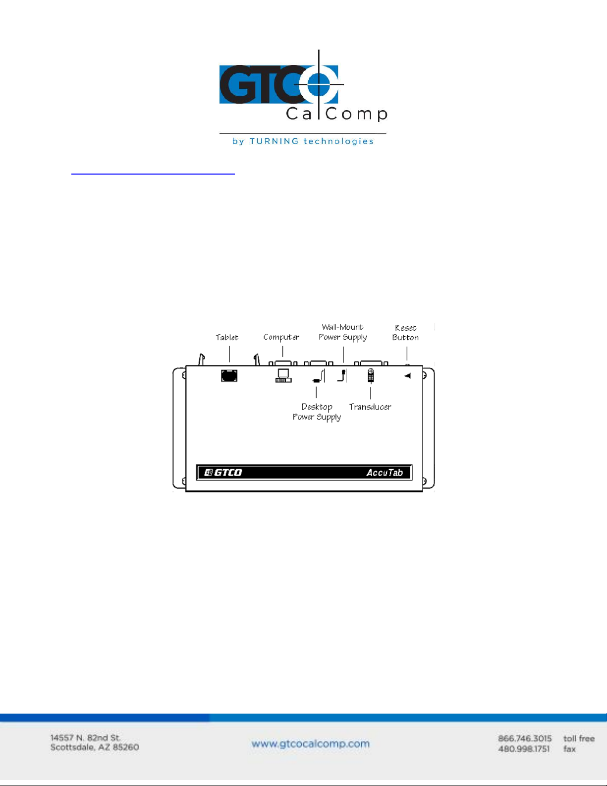
Connecting to Your Computer
GTCO CalComp by Turning Technologies provides an RS-232C cable and a 9-pin to 25-pin
adapter with each AccuTab system. Connect the cable between the port designated by the
computer icon on rear panel of the Controller shown below. Use the 9- to 25-pin adapter if
the computer has a 25-pin RS-232C connector. AccuTab interfacing in the Advanced
Operating Information section contains more information on RS-232C interfacing.
Connecting the Transducer
Three standard transducers are available for the AccuTab:
4-button cursor
16-button cursor
16-button illuminated cursor
Attach the transducer to the transducer jack on the rear panel of the controller pictured on
the previous page.
Page 6

Surface-Lit AccuTab 6
Attaching the Power Supply
Determine which power supply you have and follow the corresponding instructions. The
AccuTab controller is designed to allow a variety of power supplies to be used. Connect
only one power supply to the controller. Contact GTCO CalComp by Turning Technologies
for information on supplies other than those listed below that can be used with AccuTab.
The DP-PS12 power supply is supplied for use in North America and other locations with
120 volt line voltage. Attach the 9-pin power supply cable to the jack designated by the
desktop power supply icon on the rear panel of the controller pictured above.
The DP-UPS power supply can be used with input voltages of 90-260 volts AC and 50-60Hz.
Connect the appropriate power cord to the IEC connector on the power supply and attach
the output power cable to the 9-pin jack designated by the desktop power supply icon on
the rear panel of the controller pictured above.
Applying Power to AccuTab
With the wall mount power supplies, the AccuTab powered on as soon as the unit is
plugged into the outlet and the power switch on the Controller is turned ON. If you have a
desktop supply, turn on the power supply switch. The AccuTab performs a self-test and
responds with a series of tones when powered up.
When you apply power, you should instantly hear four short “Success!” tones and
simultaneously see the cursor lights on the transducer flash four times. This response
indicates that the AccuTab is functioning properly.
If you hear any tones before the “Success!” tones or if you do not hear the four “Success!”
tones or if the lights on the transducer do not flash four times, there is a problem.
Carefully review the installation step-by-step and correct any errors. If there is still a
problem, go the Troubleshooting section of the manual.
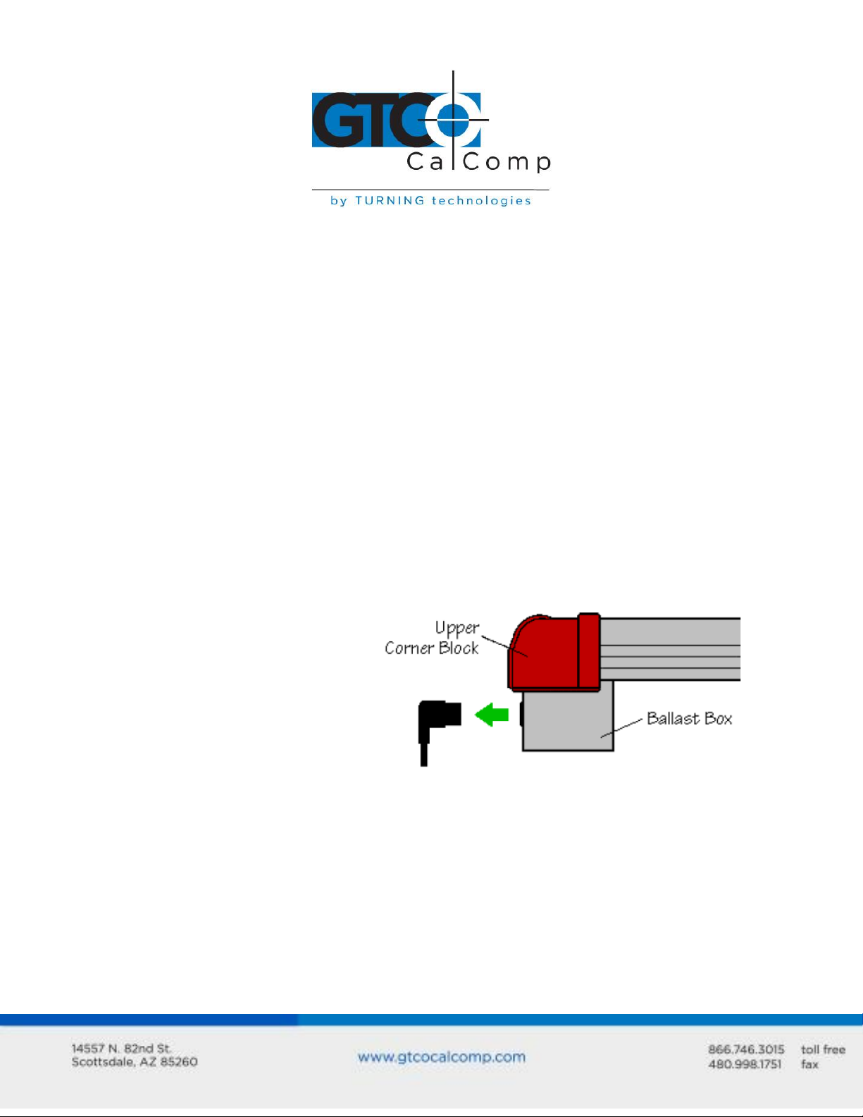
Connecting and Using the Surface-Lit Option
To connect and operate the lighting option:
Attach the power cord with the connector on the front of the ballast box (fan
enclosure) located along the back of the tablet and then plug the power cord into a
wall outlet.
Page 7
Surface-Lit AccuTab 7
The on/off power and dimmer control switches for the lighting are on the control
module found along the right side of the tablet. Set the power switch to the ON
position.
The light level is adjustable to three levels: LO, MED and HI. Select the level that is
most appropriate for your task, taking into consideration the material you are
lighting through and user comfort.
NOTE: A relatively stable AC power source is required for the illumination system to
function at maximum performance. If the light intensity of the Surface-Lit AccuTab flickers
periodically, it’s most likely due to a heavy electrical load being placed on the circuit, such
as a compressor or fan motor. This problem can be eliminated by using a separate circuit,
line conditioning equipment or a UPS power supply.
Replacing Light Bulbs on the Surface-Lit AccuTab
The expectancy life of a light bulb is approximately 2,000 hours of continuous use (a bulb
will illuminate at about 50% intensity after that time). Contact the GTCO CalComp by
Turning Technologies Technical Support Team to find out more about how to receive
replacement bulbs.
To install a replacement light
bulb(s):
1. Position the tablet parallel to
the floor with the top side
up. Unplug the power cord
from the ballast box.
Page 8

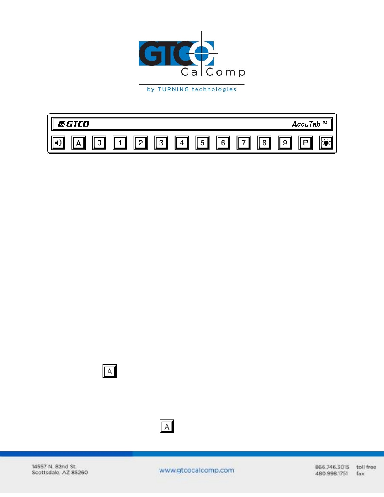
2. Identify which upper corner blocks
you will need to remove:
To replace bulb 1, remove A
and B.
To replace bulb 2, remove B
and C.
To replace bulb 3, remove C
and D.
Surface-Lit AccuTab 8
3. Using a Phillips screwdriver, remove the
appropriate upper corner blocks by
discharging the two screws indicated. (To
prevent the upper corner block from falling
and possibly being damaged, keep one
hand on it while removing the two screws.)
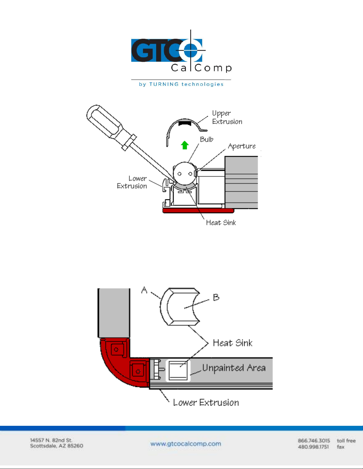
4. Using a flat-blade screwdriver as shown, gently pry the bulb up at one end and then
remove it completely. Use of excessive force could shatter the bulb.
If the heat sink stays attached to the bulb, remove any adhesive that it leaves
behind in the unpainted area on the lower extrusion (see figure in Step 5).
If the heat sink remains attached to the lower extrusion, remove it using a
pair of pliers and then discharge any adhesive that it leaves behind in the
unpainted area on the lower extrusion (see figure in Step 5).
Page 9
Surface-Lit AccuTab 9
Dispose of the bulb and heat sink.
5. Clean the unpainted area on the lower extrusion thoroughly with isopropyl alcohol.
Dry the area completely and remove adhesive liner A from the new heat sink
supplied. Place the heat sink on the lower extrusion exactly as shown and press
down on it firmly. (The heat sink must be placed within the clean unpainted area on
the lower extrusion.) Remove adhesive liner B from the heat sink.
Page 10

Surface-Lit AccuTab 10
6. Install the new bulb with its aperture facing toward the center of the tablet (see
figure in Step 4). (The aperture is the 1/4” wide clear window that runs the length of
the bulb.) Press down on each end of the bulb until it snaps into place and until the
bulb makes contact with the adhesive on the heat sink.
7. Replace the upper extrusion. Make sure that the ends of the upper extrusion align
with the ends of the lower extrusion.
8. Discharge the upper corner blocks. Do not over tighten the screws.
Configuring Your Computer
Apply power to the computer. Configure the graphic application software to operate with
AccuTab. Many application programs provide configuration information for specific
digitizers. If the GTCO CalComp by Turning Technologies AccuTab digitizer is not listed, you
can use the configuration for GTCO CalComp by Turning Technologies Digi-Pad Type 5 or
Type 5A (T5/T5A), CalComp 9100/9500 or Summagraphics Microgrid III.
If necessary, install the appropriate digitizer driver(s) from the Digitizer Driver CD supplied
(AutoCAD, Windows and mouse drivers are included). Insert the diskette into drive A or B.
From the DOS prompt, type a:\install or b:\install and then follow the onscreen
instructions.
NOTE: Install only the drivers that are necessary for the AccuTab to work with your
application software.
Mounting Transducer Holders
Each transducer comes with a holder. Remove the protective paper, exposing the adhesive
layer on the bottom of the holder. Place the holder in a convenient location on the tablet,
outside the marked active area.
Page 11
Using the AccuSet Menu
Use the AccuSet Menu to:
Configure AccuTab for specific application programs
Use the Custom Configuration Menu
Control the alarm
Reset the AccuTab
Control the Illuminated Cursor lamps
Surface-Lit AccuTab 11
Configuring for Specific Application Programs
You can use the AccuSet Menu to quickly change the AccuTab’s operating characteristics to
match those required by different application programs running on the computer.
To configure AccuTab for use with specific application programs:
1. In Table 1, find the application program you’ll be using with AccuTab. Please note
the corresponding AccuSet Code.
If your application program is not listed in Table 1, find the configuration
settings that apply to your application program in Table 2 and use that
AccuSet Code.
If an appropriate AccuSet Code is not listed in Table 2, then use the Custom
Configuration Menu to set up the AccuTab.
2. Select the block on the AccuSet Menu. This lets the AccuTab know you are
about to set a new configuration. You will hear one short beep.
NOTE: The proximity light will turn on only when the transducer is over a AccuSet
Menu block that is a valid selection (for example, the proximity light will not turn on
over a digital block until the block has been selected).
Page 12

Surface-Lit AccuTab 12
3. On the AccuSet Menu, select the two digits of the AccuSet Code for your application
program. You will hear one short beep after the first digit. Then, following the
second digit, you will hear the four short “Success!” tones informing you that the
AccuTab has reset itself to the new configuration. The proximity light on the
transducer will also flash four times.
To cancel a menu selection before it is complete, digitize a point in the tablet’s main
active area. Three long beeps will indicate that the AccuSet selection process has
been aborted. The proximity light on the transducer will also flash three times.
4. Run the corresponding application program on your computer.
NOTE: Hardware flow control is not supported by the AccuTab Controller. If you
have an application that requires this option, contact GTCO CalComp by Turning
Technologies for alternatives.
Flow Control
Flow control is the process of regulating the traffic or flow of data between two RS-232C
devices. Flow control prevents the transmission and subsequent loss of data if the receiver
is not ready to accept it. Examples of devices that use flow control are: a printer to signal
buffer full; a modem to indicate carrier detect; and a time-shared computer that services
multiple users on a time-available basis.
There are two kinds of flow control:
Software flow control is often implemented over communication links where only a
3-wire cable is used (Transmit Data, Receive Data, Ground) or over telephone lines.
The sending device (such as the AccuTab) will immediately stop sending data when
it receives an ASCII XOFF character (CTRL-S, hex 13). Transmission will resume when
it receives an ASCII XON character (CTRL-Q, hex 11). Character flow control will work
with the straight through cable and the null modem cable.
Hardware flow control is not commonly used with digitizers and is therefore not
supported by the AccuTab Controller.
Flow control may not be needed when a terminal or digitizer is directly connected to a
single-user computer. Most digitizing application software does not use flow control of
either kind.
Page 13
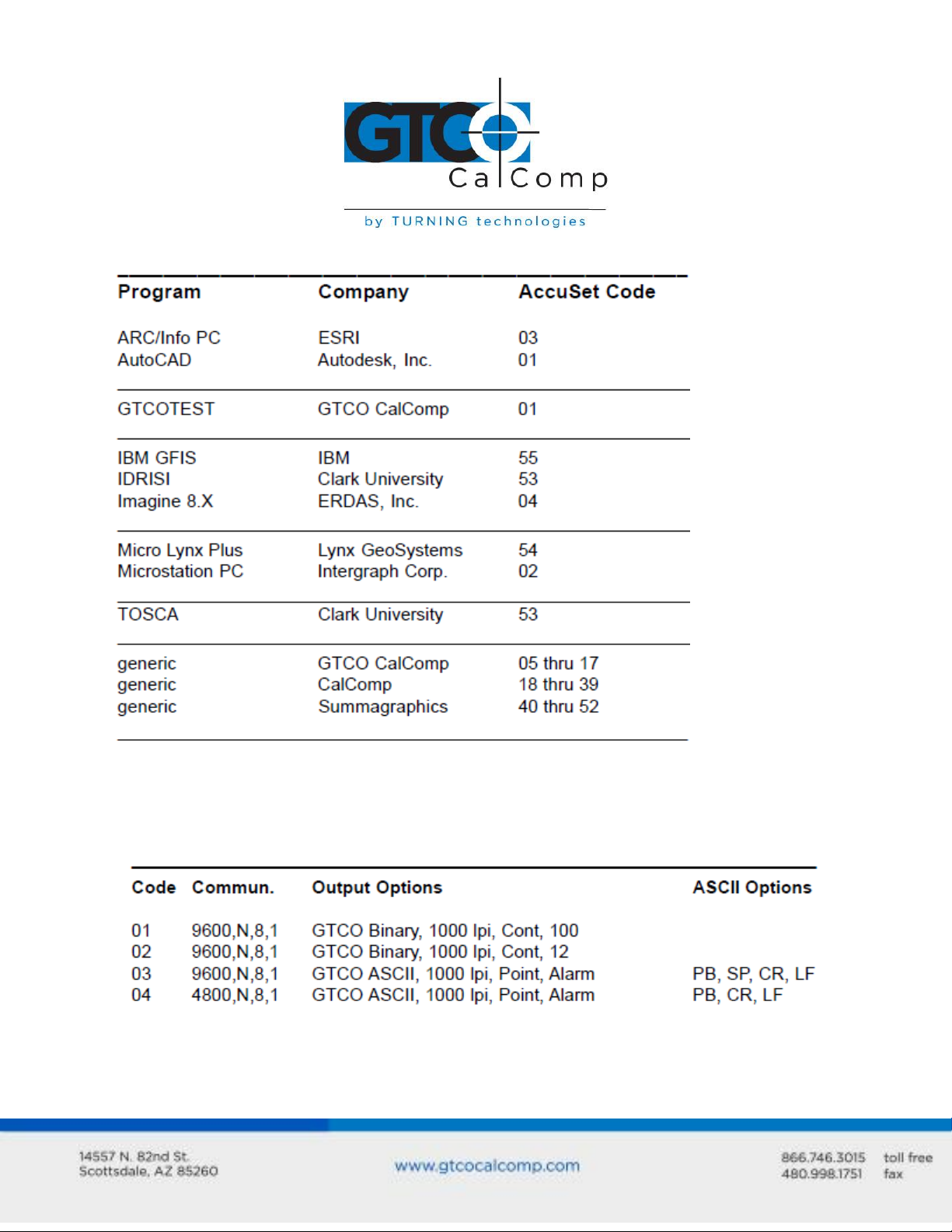
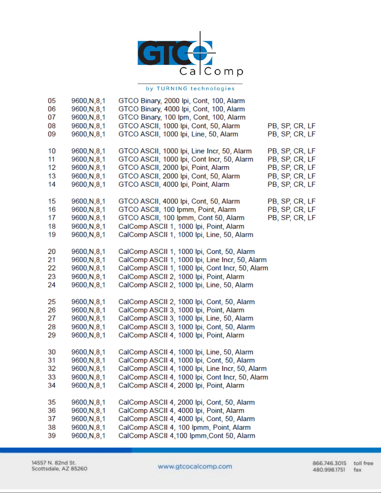
Table 1: AccuSet Menu Codes for Selected Application Programs
Surface-Lit AccuTab 13
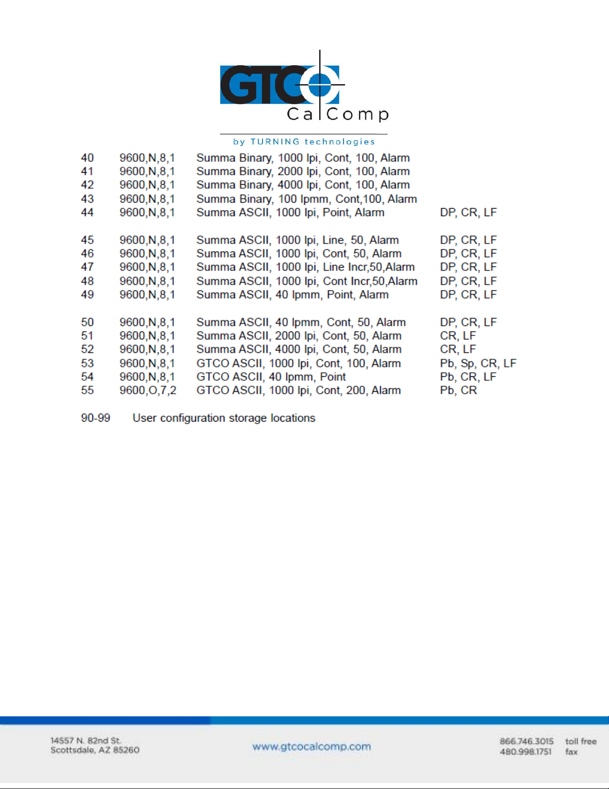
Table 2: Configuration Details for AccuSet Menu Codes
NOTE: Max = 100 coordinates/second lpi = lines per inch lpmm = lines per millimeter
Page 14
Surface-Lit AccuTab 14
Page 15
Surface-Lit AccuTab 15
Page 16
Surface-Lit AccuTab 16
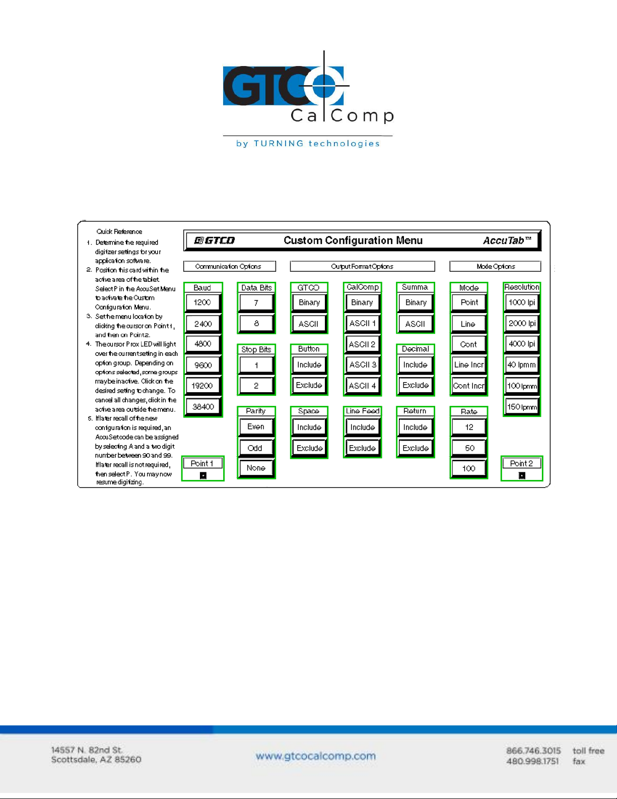
Introduction to the Custom Configuration Menu
The AccuTab with its Controller uses the Custom Configuration Menu to control baud rate,
data format and other operating characteristics.
Using the Custom Configuration Menu
If your application does not have an AccuSet Menu Code or if a different configuration is
required, then use the Custom Configuration Menu to format AccuTab. The Custom
Configuration Menu replaces the 24 switches associated with the older Type 5A Controller.
Configurations you set up can be stored in any of ten user-definable AccuSet locations
(codes 90 through 99) for recall at a later time. This allows the AccuTab to be easily
switched between applications.
Page 17
Surface-Lit AccuTab 17
To configure AccuTab with the Custom Configuration Menu:
1. Place the Custom Configuration Menu card (included with the system) in the active
area of the tablet. The entire menu must be in the active area. (Hold the menu in
place to keep it from moving during the configuration process.)
2. Select the menu block at the right end of the AccuSet Menu. The proximity light
on the transducer will flash slowly, indicating that the Custom Configuration Menu
mode is now ready to receive Alignment Point 1.
3. You must notify the Controller where the Custom Configuration Menu card is
located on the tablet. Select Alignment Point 1 (small blue square) in the lower left
corner of the card. The proximity light on the transducer will flash rapidly, indicating
that the system is waiting to receive Alignment Point 2.
4. Choose Alignment Point 2 (small blue square) in the lower right corner of the card.
The LED will only light up if passed over an active menu block on the Custom
Configuration Menu (or is moved off the menu card into the active area of the
tablet).
If the invalid alignment points are selected or if the Custom Configuration Menu is not
entirely in the active area, the menu mode will be aborted. This is indicated by three long
beeps from the alarm and three long flashes from the proximity light on the transducer.
5. Configure the AccuTab by selecting the function blocks that correspond to the
settings you want.
6. Review the configuration to ensure that the proper settings have been selected.
Pass the transducer down each group of options; the proximity light will turn on
when the transducer is over the active choice.
7. After making the selections, two options are presented: 1) save as a temporary
configuration or 2) save the configuration in a user-definable location for later recall.
To Save the Configuration Temporarily: Select on the AccuSet Menu.
You will hear four “Success!” tones and see four proximity light flashes when
you successfully save a configuration. The configuration is saved in a
temporary location, where it will be retained even if the unit is powered off
Page 18
Surface-Lit AccuTab 18
or reset. However, if another AccuSet code is entered, this temporary
configuration is lost and cannot be recalled without configuring the AccuTab
again.
To Save the Configuration in a User-Definable Location: Choose and
then a two digit value ranging from 90 to 99 on the AccuSet Menu. You will
hear four “Success!” tones and see four proximity light flashes when you
successfully save a configuration. Saved configurations allow you to switch
between applications quickly. Locations 90-99 retain configurations even if
the AccuTab is turned off or reset.
8. The configuration set up is now complete. Remove the Custom Configuration Menu
and store it in a safe place for future reference.
Configuration parameters for the AccuTab are divided into three separate
categories:
Communication Options
Output Format Options
Mode Options
Communication Options
Baud: The rate, in bits/second, at which characters are transmitted across the RS-
232C serial interface. Choices are: 1200, 2400, 4800, 9600, 19200 or 38400.
Data Bits: Data bits represent the actual data being sent from one device to
another. Both devices must be set for the same number of data bits. Choices are:
Seven (7) or Eight (8).
Stop Bits: Each character has one or two stop bits, which tell the receiving device
that a character is complete. The number of stop bits usually does not matter.
Setting for two stop bits instead of one may overcome a mismatch in parity or data
bits. Choices are: One (1) or Two (2).
Parity: One bit can be allocated for parity (parity is a simple error-detecting
scheme). Both devices (sending and receiving) must be set for the same parity –
Page 19

Surface-Lit AccuTab 19
either odd parity or even parity – or they must be set for no parity. Choices are:
None (N), Even (E) or Odd (O).
Output Format Options
GTCO: Selects GTCO-compatible formats. See Advanced Programing Information for
greater detail on GTCO format structure. Choices are: Binary or ASCII.
CalComp: Selects CalComp-compatible formats. See Advanced Programming
Information for greater detail on CalComp format structure. Choices are: Binary,
ASCII 1, ASCII 2, ASCII 3 or ASCII 4.
Summa: Selects Summagraphics-compatible formats. See Advanced Programming
Information for greater detail on Summagraphic format structure. Choices are:
Binary or ASCII.
ASCII formats can be modified by including or excluding a button code, decimal point,
carriage return or line feed, depending on whether GTCO, CalComp or Summa formats
have been selected.
Button: Defines whether the Pushbutton (Pb) value is included in the ASCII output
report. This option is available only with GTCO formats. Choices are: Include or
Exclude.
Space: Defines whether the Space (Sp) character (hex 20) is included in the ASCII
output report as a delimiter between the X and Y coordinate values. This option is
available only in GTCO formats. Choices are: Include or Exclude.
Decimal: Defines whether the period character (hex 2E) is included in the ASCII
output report between the units and tenths digits. This option is available only in
Summagraphics formats. Choices are: Include or Exclude.
Return: Defines whether the Carriage Return (CR) character (hex 0D) is included in
the ASCII output report as a terminator. This option is available in GTCO and
Summagraphics formats. Choices are: Include or Exclude.
Line Feed: Defines whether the Line Feed (LF) character (hex 0A) is included in the
ASCII output report as a terminator. This option is available in GTCO, CalComp and
Summagraphics formats. Choices are: Include or Exclude.
Page 20
Surface-Lit AccuTab 20
AccuSet Menu:
Select the menu block
GTCO Commands:
Send command AD.
AccuSet Menu:
Select the menu block
GTCO Commands:
Send command AE.
Mode Options
Mode: Defines how output reports are sent from the digitizer. Choices are: Point,
Line, Continuous, Line Incremental or Continuous Incremental.
Rate: Determines how fast output reports will be transmitted from the digitizer.
Choices are: 12, 50 or 100 reports per second.
Resolution: The smallest reported value returned by the digitizer. Choices are:
1000 lpi, 2000 lpi, 4000 lpi, 40 lpmm, 100 lpmm or 150 lpmm.
Controlling the Alarm
There are two ways to toggle the alarm on or off:
Select the block on the AccuSet Menu.
Use the below remote commands.
Controlling the Alarm Using Remote Commands
An alarm (audio tone) is provided so AccuTab can inform you of certain conditions. The
alarm can be enabled or disabled by the AccuSet Menu or commands.
To hear only critical tones, turn the alarm off:
To hear all tones, turn the alarm on:
When you move the cursor over the block on the AccuSet Menu, the Proximity
indicator (red) will light if the alarm is currently enabled.
Page 21

Surface-Lit AccuTab 21
Resetting AccuTab
There are four ways to reset AccuTab:
Enter AccuSet code 00 on the AccuSet Menu.
Press the reset button on the rear panel of the Controller.
Turn power off and on.
Send remote commands described in the Advanced Operating Information section.
When one of these events occurs, AccuTab will revert to the configuration that was last
defined. Any remote commands that were active before the result will be lost.
Controlling the Illuminated Cursor Lamps
To toggle the Illuminated Cursor’s lamps on or off:
Select the block on the AccuSet Menu.
Lamps will automatically turn off if the cursor remains motionless for about 15
minutes. To turn the lamps on again, just move the cursor.
Transducer Lights
Different transducers have a variety of indicator lights on them. This section describes
what the indicators notify about the operation of the AccuTab.
Proximity Indicator (red): Standard on all transducers and is on when the transducer
is within the tablet’s active area. Conversely, it is off when the transducer is outside
the active area. Under most conditions, the AccuTab will not generate coordinate
formats when the transducer is outside the active area.
This indicator is also used to communicate status information to you when you’re using
the Custom Configuration Menu or AccuSet Menu.
Point/Line Indicator (green): Available on the 16-button cursor only and tells you
which digitizing mode is in use. If Point Mode is active, the light is off. If Line Mode
or Continuous Mode is active, the light is on.
Status Indicator (yellow): Available on the 16-button cursor only (not available on
the Illuminated Cursor). This indicator is controlled by remote commands.
Application programs can turn the status indicator on and off by sending the
appropriate commands.
Page 22

Surface-Lit AccuTab 22
AccuTab Tones
AccuTab produces an alarm in the form of audio tones to inform you of various events.
The table below describes the kinds of tones you may hear while operating the digitizer.
Troubleshooting Guide
GTCO CalComp by Turning Technologies wants your experience with AccuTab to be a
successful one. If you ever encounter a problem, please follow the steps below:
1. Install properly first.
This troubleshooting guide assumes you have already correctly installed AccuTab
according to the detailed instructions in the Installing Your AccuTab section. If you
have not followed the step-by-step instructions in that section, do so now.
2. Follow the troubleshooting flowcharts and other instructions that follow in
this guide.
Record any unusual observations. Your notes will be useful if you need assistance
from the GTCO CalComp by Turning Technologies Technical Support Team.
3. If your system still does not work.
Call GTCO CalComp by Turning Technologies Technical Support at 1-866-746-3015
(in the U.S. or Canada) or email us at gtco.support@gtcocalcomp.com. Outside the
Page 23

U.S. or Canada, contact your local GTCO CalComp by Turning Technologies office or
dealer. Be prepared to discuss the observations you made while troubleshooting.
Procedure A: Begin Troubleshooting
Surface-Lit AccuTab 23
Page 24

Procedure B: Troubleshooting
Surface-Lit AccuTab 24
Page 25

Procedure C: Troubleshooting
Surface-Lit AccuTab 25
Page 26

Procedure D: Troubleshooting
Surface-Lit AccuTab 26
Page 27

Procedure E: Troubleshooting
Surface-Lit AccuTab 27
Page 28

Surface-Lit AccuTab 28
where P
XXXXXX
YYYYYY
= pushbutton code
= X coordinate data
= Y coordinate data
Using GTCOTEST
GTCOTEST is a program that runs on your PC. It can be used to perform communication
and diagnostic tests on an installed AccuTab. GTCOTEST is provided on the diskette you
received with the system.
1. Select AccuSet Code 01 on your AccuTab (9600, N, 8, 1, GTCO Binary, 1000 lpi, Cont,
100).
2. To run GTCOTEST, insert the TabletWorks CD in the CD-ROM drive. GTCOTEST will
work only if no Wintab drivers are installed. From the DOS prompt, switch to the
folder on the CD that contains the gtcotest.exe files. Type gtcotest and follow the
onscreen instructions.
3. Once GTCOTEST’s third screen has been reached, the pull-down menu headings will
read: Communications, Diagnostics, Setup and Check Output. Select Read Switches in
the diagnostics window. Communication has been established if 0’s and 1’s appear
in the display box.
If GTCOTEST displays the Serial input timeout error message, try selecting
another COM port in the Communications window.
If GTCOTEST displays the Cannot open COM port error message, try selecting
another COM port in the Communications window. (Each PC serial port has
a physical address that corresponds to a specific COM port. If there is only
one serial port installed in the computer, it will be assigned as
COM1regardless of its physical address. GTCOTEST examines only the
physical address.)
4. Once communication is established, select the Read Tablet Size and Read Version
options, making a note of the responses. This can easily be done with your print
screen key if a printer is connected to your computer.
5. Choose Check Output and then select High Res Binary.
6. Place the transducer in the active area on the tablet.
7. If everything is working properly, you should see data displayed on your computer
screen in the following format: P XXXXXX YYYYYY
8. When you move the transducer around the active area, the X and Y coordinate data
should change. When you press different cursor buttons, the pushbutton code
should adjust.
Page 29

Surface-Lit AccuTab 29
9. If GTCOTEST indicates that the digitizer is functioning properly, check your software
application setup and AccuSet code for accuracy. If you have any questions about
your results or need help running GTCOTEST, contact our Technical Support Team
at 1-866-746-3015.
Technical Information
The AccuTab digitizer’s design provides the highest level of data integrity including
coordinate resolution, measurement accuracy and data stability – supported by high
reliability and system compatibility.
AccuTab incorporates a digitizing technique called Forward/Reverse Scan Averaging™, which
factors out errors resulting from slight changes in the angle and height of the digitizer
cursor. This technology improves accuracy even at the edge of the tablet’s active area (the
location where most digitizers lose accuracy). The AccuTab will maintain its original data
integrity over the long term without the need for periodic recalibration, adjustments or
maintenance.
The point-sensing grid (located inside the tablet) is the single most important determinant
of AccuTab’s accuracy. To achieve the extremely tight tolerances required for the AccuTab,
its grid is photographically printed and chemically etched on a composite glass-fiber
substrate. This critical component is manufactured in a large scale, high-precision, printed
circuit board print and etch production facility owned and operated by GTCO by Turning
Technologies.
The performance of every AccuTab is verified on a high-precision automated measurement
fixture. A report generated by this system is included with the AccuTab. GTCO by Turning
Technologies guarantees that each AccuTab will maintain its performance for five years.
The AccuTab is compatible with all leading hardware and software, including class one
compatibility with ESRI’s ARC/INFO software.
Page 30

AccuTab Specifications
Dimensions/Weight
(AccuTab)
Active Area
24” x 36”
36” x 48”
42” x 60”
Footprint
32.75” x 46”
44.5” x 60”
52.5” x 68”
Weight
26 lbs.
40 lbs.
55 lbs.
Avg. Ship Wt.
45 lbs.
71 lbs.
104 lbs.
Dimensions/Weight
(Surface-Lit AccuTab)
Active Area
20” x 24”
24” x 36”
36” x 48”
Footprint
31” x 36”
35” x 48”
47” x 63”
Weight
50 lbs.
68 lbs.
102 lbs.
Avg. Ship Wt.
70 lbs.
90 lbs.
130 lbs.
Technology
Patented electromagnetic
Resolution
Up to 4000 lpi or 150 lpmm real resolution
Absolute Accuracy
(certified)
±0.005 in / ±0.127 mm (Standard)
±0.002 in / ±0.051 mm (Standard)
±0.003 in / ±0.076 mm (Standard)
±0.0075 in / ±0.190 mm (Standard)
Repeatability
1 LSB (least significant bit)
Proximity
AccuTab: 1.0” (25.4 mm) nominal
Surface-Lit AccuTab: 0.5” (13 mm) nominal
Self-Diagnostics
Automatic testing, drive electronics and microprocessor
Operating Modes
Point, line, continuous, line incremental, continuous incremental
and remote request
Baud Rate
Up to 38,400
Power Supply
100/120/220/240 VAC, 50/60 Hz
Operating Temperature
41 to 115°F/5 to 46°C
Humidity Range
10 to 95%, noncondensing
Storage Temperature
0 to +150°F/-18 to +68°C
Altitude Range
0 to 10,000 ft./0 to 3,077 m
Certifications
UL, CSA, FCC-B, VDE-B, CE
Cursor Switches
Elastomeric keypad, rated life over 1 million actuations
Output Formats
GTCO T5/5A Binary and ASCII, CalComp 3400, Summagraphics
Surface-Lit AccuTab 30
Page 31

Surface-Lit AccuTab 31
Sources of Power
GTCO CalComp by Turning Technologies provides a standard wall-mount power supply, the
DP-PS12, for use in the U.S.A with the AccuTab Controller. If you want to use another wall
mount power source due to different input power requirements, it must supply the
following output voltage:
+9 VDC at 1.0 Ampere.
The following figure shows the dimensional specifications and the polarity of the power
connector.
As an alternative source of power, GTCO CalComp by Turning Technologies also offers the
capability of using the DP-UPS for 110 VAC or 90-260 VAC operation. If you want to use
another power source with the 9-pin subminiature-D connector provided on the AccuTab
Controller, it must supply the following voltages:
+5.0 ± 0.1 VDC at 1.0 Amperes
+12 ± 1.0 VDC at 100 Milliamps
Ripple on all voltages must be less than 30 millivolts.
Your power supply will need a female 9-pin
subminiature-D metal shell connector (mates to 9-pin
male D connector, indicated by the desktop power
supply icon, on the AccuTab Controller). The table below
shows the pin functions for this connector. The power
cable must be shielded, with the shield connected to the
metal connector shell at the AccuTab end and connected
to earth ground at the power supply end.
Page 32

Surface-Lit AccuTab 32
Advanced Operating Information
AccuTab Interfacing
Important: The following information is not required for normal AccuTab operation.
Connecting AccuTab to a computer is usually straight-forward (see Installing AccuTab
section in this manual). If you do not have a typical interfacing situation, the information in
this section will help you set up the AccuTab and connect it to another device.
The AccuTab is equipped to communicate via RS-232C, a widely used serial interface
between computers and peripherals. RS-232C is a (more or less) standard interface, and
cables and connectors are available from a variety of sources. Most computers and
peripherals either have an RS-232C interface or can be equipped with one.
A mini-tutorial on RS-232C interfacing
This section provides basic information about RS-232C communications. There are three
areas to consider when using RS-232C:
Character format and baud rate
Cabling
Flow control
Character Format and Baud Rate
Character format and baud rate govern how bits are assembled to form characters the
speed of transmission. Both the AccuTab and the computer must have identical formats
and rates. These parameters are discussed in the Introduction to the Custom
Configuration Menu section.
Cabling
Cabling carries the data from one device to the other. A majority of RS-232C cables have
either male 9-pin or 25-pin subminiature D connectors on their ends to match female
connectors on the equipment. The Digi-Pad is supplied with a 9-pin-to-9-pin serial cable
and a 9-pin-to-25-pin adapter.
Data Terminal Equipment (DTE), such as printers, digitizers and computers, usually (but not
always) transmit data on Pin 2 and receive data on Pin 3. Data Communications Equipment
(DCE), such as modems, generally transmit data on Pin 3 and receive data on Pin 2. Thus,
connecting a terminal (DTE) to a modem (DCE) may be as simple as connecting them with a
Page 33

Surface-Lit AccuTab 33
straight-through cable that is wired pin-to-pin (i.e., 1 to 1, 2 to 2, etc.). This figure shows
such a cable. The AccuTab Controller is typically connected in this manner using the cable
supplied by GTCO CalComp by Turning Technologies.
Connecting DTE to DTE, or DCE to DCE, may require a different strategy to get the data on
the correct wires. The below figure shows a cable that can work in this situation. It is called
a null modem cable and it fools both devices into thinking they are talking with the right
kind of receiver. This cable routes Pin 2 to Pin3 and Pin 3 to Pin 2.
Page 34

Surface-Lit AccuTab 34
Your computer may have a 25-pin RS-232C connector, rather than a 9-pin connector. If so,
use the 9- to 25-pin adapter supplied with the AccuTab. The figure below shows how this
adapter is wired internally.
Flow Control
Flow control is the process of regulating the traffic or flow of data between two RS-232C
devices. Flow control prevents the transmission and subsequent loss of data if the receiver
is not ready to accept it. Examples of devices that use flow control are: a printer to signal
buffer full; a modem to indicate carrier detect; and a time-shared computer that services
multiple users on a time-available basis.
There are two kinds of flow control:
Software flow control is often implemented over communication links where only a
3-wire cable is used (Transmit Data, Receive Data, Ground) or over telephone lines.
The sending device (such as the AccuTab) will immediately stop sending data when
it receives an ASCII XOFF character (CTRL-S, hex 13). Transmission will resume when
it receives an ASCII XON character (CTRL-Q, hex 11). Character flow control will work
with the straight through cable and the null modem cable.
Page 35

Surface-Lit AccuTab 35
Hardware flow control is not commonly used with digitizers and is therefore not
supported by the AccuTab Controller.
Flow control may not be needed when a terminal or digitizer is directly connected to a
single-user computer. Most digitizing application software does not use flow control of
either kind.
Remote Commands
NOTE: The following information is not required for normal AccuTab operation. If you are
programming for the AccuTab product line, the details will be helpful.
AccuTab can receive commands from other devices through its RS-232C port. Commands
cause the AccuTab to change the way it operates, to use certain coordinate formats and to
do other things as directed by you or by an application process.
Commands offer another way to control AccuTab operation besides the Custom
Configuration Menu. Certain AccuTab functions can be carried out only through
commands.
If you are developing your own application software, be cautious about using commands in
your program. An interruption in power to the AccuTab or a Reset will cause it to discard
any command changes it has received. This could leave your program confused about
what the AccuTab is doing. A full system reset would then be needed to get the AccuTab
and computer coordinated again. A prudent programmer will limit command and control
of an AccuTab.
The AccuTab responds to three kinds of commands:
GTCO AccuTab standard commands (with some omissions and additions)
CalComp emulation commands
Summagraphics emulation commands
Page 36

Surface-Lit AccuTab 36
GTCO CalComp by Turning Technologies AccuTab Command Summary
Functional Control Commands
Page 37

Surface-Lit AccuTab 37
Select Point Mode
Select Line Mode
Select Continuous Mode
Select Line Incremental Mode
Select Continuous Incremental Mode
Code: PT
Code: LN
Code: CN
Code: IC
Code: CL
Functional Control Commands
Reset Code: RS
The Reset command will reset the Controller to the last known configuration, clearing all
previous commands sent to the Controller. If a SuperSet Menu configuration has been
selected, the Reset command will reset the Controller to the SuperSet Menu value.
Page 38

Surface-Lit AccuTab 38
Select Remote Request Mode
Code: RM
Read Current Coordinate
Code: hex 02 (Ctrl-B)
Set Increment Value
Code: IV
Send Coordinates 0,0 When Transducer is Out of Active Area
No Output When Transducer is Out of Active Area
Code: OP
Code: IP
The Read Current Coordinate causes AccuTab to output a coordinate while it is in Remote
Request Mode. This command can be sent to the AccuTab only when it is digitizing and
only when Remote Request Mode has been selected by command RM. The Read Current
Coordinate command will be ignored if AccuTab is in Command Mode. Please note that
this command is not two ASCII characters. It is the one-byte-long STX character, CTRL-B
(hex 02). AccuTab responds to the Read Current Coordinate command by transmitting one
format.
In Line Incremental and Continuous Incremental modes, the AccuTab outputs a coordinate
when the transducer is moved beyond a certain incremental distance in either the X or Y
direction. The default increment is 0.01”. The Set Increment Value command allows the
user to select the distance which the transducer must move to initiate coordinate output.
It works as follows:
1. Enter Command Mode by sending a CTRL-A.
2. After receiving the > prompt, send IV and a <CR> (hex 0D).
3. The Controller will respond with a <.
4. After receiving the <, send a three-digit string ranging from 000 to 999. This string
represents an increment value of 0.000 to 0.999 inch.
5. When the Controller receives the last character it will respond with a > prompt and
await the next command.
Certain situations require that the AccuTab be able to send a coordinate when the
transducer is out of the active area. Command OP permits coordinates to be sent under
this condition. Since valid coordinates are not available when the transducer is out of the
active area, coordinates 0,0 are substituted in the format. When this command has been
executed, digitizing modes operate normally, whether the transducer is in the active area
or not. Command IP returns AccuTab to the default condition, in which coordinates are
sent only when the transducer is in the active area.
Page 39

Surface-Lit AccuTab 39
Set Digitizing Rate
Code: Rx
Digitizing rate, formats/second
Digitizing rate command
12 100 100 5 10 50
R1 R2 R3 R4 R5 R6
Change Mode Character
Code: MC
Select English Measurement Scale
Select Metric Measurement Scale
Code: IN
Code: MT
Enable Echo Mode
Disable Echo Mode
Code: EM
Code: hex 0F (Ctrl-O)
Coordinates can be sent from AccuTab at rates from 5 to 100 coordinates per second. The
second character in this command sets the rate, as shown in the table below. Actual rates
are limited by the communication baud rate and coordinate type you have selected. The
rates shown here are, therefore, maximum rates.
Rate Commands
Some applications may have a predefined meaning for the SOH (CTRL-A) character used to
invoke Command Mode. If so, invoking Command Mode may cause your system to do
something else. You can set the AccuTab so that a character other than SOH is used to
begin Command Mode. Here is how to make the substitution:
1. Enter Command Mode.
2. Send MC, followed by a <CR>. Super L III responds with the prompt message:
ENTER NEW COMMAND MODE CHARACTER:
3. Enter the desired mode change character. The new mode character can be any
character except ESC (CTRL-[, hex 1B), <CR> (CTRL-M, hex 0D), CAN (CTRL-X, hex 18),
VT (CTRL-K, hex 0B), XON (CTRL-Q, hex 11) or XOFF (CTRL-S, hex 13).
Now, when you want to enter the Command Mode, send the new character. All other
command operations remain unchanged.
Invoking these commands causes AccuTab to scale coordinates in the desired
measurement system. The digitizer measures in only one scale at a time. See
Measurement Scales for additional information on how scale selection affects coordinate
data.
These commands control echoing by the AccuTab. When enabled, echoing transmits each
received character back to the sending device.
Page 40

ASCII Format Output
Code: AS
Command causes coordinates to be transmitted in ASCII. ASCII coordinates can be
modified by the Low/High/Highest Resolution, Pushbutton, Space, Carriage Return and Line
Feed commands and by menu settings.
Binary Format Output
Code: BI
Command causes coordinates to be transmitted in binary format. Binary coordinates can
be modified by the Low/High/Highest Resolution commands and by menu settings.
Low Resolution
Code: LR
Command modifies ASCII and binary formats. If ASCII formats have been selected, the Low
Resolution command causes the least significant digit to represent 0.01 inch or 0.1
millimeter, depending on whether English or metric scale has been selected. Both X and Y
portions of each ASCII format will be four digits long if in English scale or five digits long if in
metric scale.
If the binary format is selected, the least significant bits represent 0.005 inch or 0.1
millimeter, depending on whether English or metric scale has been selected.
High Resolution
Code: HR
Command modifies ASCII and binary formats. If ASCII formats have been selected, the
High Resolution command causes the least significant digits to represent 0.001 inch or
0.025 millimeter, depending on whether English or metric scale has been selected. Both X
and Y portions of each ASCII format will be six digits long.
If binary formats have been selected, the least significant bits represent 0.001 inch or 0.025
millimeter, depending on whether English or metric scale has been selected.
Highest Resolution
Code: H1
Command modifies ASCII and binary formats. If ASCII formats have been selected, the
Highest Resolution command causes the least significant digits to represent 0.0005 inch or
0.01 millimeter, depending on whether English or metric scale has been selected. Both X
Format Selection Commands
Surface-Lit AccuTab 40
Page 41

Surface-Lit AccuTab 41
and Y portions of each ASCII format will be six digits long.
If binary formats have been selected, the least significant bits represent 0.0005 inch or 0.01
millimeter, depending on whether English or metric scale has been selected.
Pushbutton Include
Pushbutton Exclude
Code: PI
Code: PE
Space Include
Space Exclude
Code: SI
Code: SE
Carriage Return Include
Carriage Return Exclude
Code: CI
Code: CE
Line Feed Include
Line Feed Exclude
Code: LI
Code: LE
Enable Alarm
Disable Alarm
Code: AE
Code: AD
Sound Tone
Tone Pause
Code: T1
Code: T0
These commands control the presence of the corresponding characters in ASCII formats.
Pushbutton codes and where they appear in coordinates are described in the Advanced
Programming Information section. When included, the space is an additional character
separating the X and Y components of the coordinate data. When included, the LINE FEED
is an additional character following the <CR>.
Alarm, Status Indicator and Cursor Illumination Commands
These commands enable or disable the audible alarm. When enabled, a short tone will
sound when a transducer switch is pressed. When disabled, the alarm will not sound in
response to transducer switch presses, but it may be sounded by remote commands and
will be active during diagnostics and in the menu modes.
The Sound Tone command allows a remote device to sound the AccuTab’s audible alarm.
Tone Pause provides a pause between tones. Tones and pauses are in 0.25 second
intervals. Tone commands are not affected by the Disable Alarm command.
Page 42

Surface-Lit AccuTab 42
Turn Status Indicator or Cursor Illumination On
Tone Status Indicator or Cursor Illumination Off
Code: ON
Code: OF
Transmit Version Number
Code: VR
Display Tablet Active Area Size
Code: SZ
Read Tablet Diodes
Code: RD
These commands control the state of the yellow status indicator on the 16-button cursor or
the cursor lamps on the illuminated cursor.
Diagnostic Commands
Command causes AccuTab to determine and transmit the version number of the firmware
currently installed.
AccuTab automatically determines the size of the attached tablet’s active area when it is
turned on or reset. This command can be used to send the information to another device.
The size is encoded as four digits: two digits representing vertical size in inches followed by
two digits representing horizontal size in inches. For example, the 36” x 48” AccuTab sends
the digits 3648 in response to this command.
Diagnostic command causes the AccuTab to examine the attached tablet and send the
results to another device for display. A “1” means a diode is present and a “0” means a
diode is missing.
Page 43

Surface-Lit AccuTab 43
Programming Example: To Send Version Command and Display Results
This QBASIC program interacts with AccuTab in Command Mode. In this example, the
program activates Command Mode, sends the VR command and displays the resulting
firmware version transmitted by the AccuTab.
1. Configure AccuTab for 9600, N, 8, 1, GTCO ASCII and Point (AccuSet 03).
2. Enter and run this QBASIC program:
CalComp Emulation Commands
AccuTab recognizes a subset of the CalComp 9500 command set. Space does not permit a
detailed description of CalComp commands. However, most of the commands in this
subset have equivalent AccuTab commands. For further information about the operation
of those commands, please refer to the AccuTab command or function description in the
GTCO CalComp by Turning Technologies AccuTab Command Summary.
NOTE: CalComp commands must be terminated with a <CR>, which is not shown in the
codes listed here. Commands can be strung together by substituting an @ character for
the <ESC>% sequence after the first command and postponing the <CR> until the end of
the multiple command string.
Page 44

Surface-Lit AccuTab 44
Disable/Enable Echo
Code: ESC%En
Where n=0 to 3 (0 and 2 disable echo, 1 and 3 enable echo). If n is not included in the
command, echo is toggled on or off from its previous state.
(Equivalent to Enable Echo Mode, EM and Disable Echo Mode, hex 0F.)
Page 45

Surface-Lit AccuTab 45
Page 46

Surface-Lit AccuTab 46
Page 47

Surface-Lit AccuTab 47
Summagraphics Emulation Commands
AccuTab recognizes a subset of the Summagraphics UIOF command set. Space does not
permit a detailed description of Summagraphics commands. However, most of the
commands in this subset have equivalent AccuTab commands. For further information
about the operation of those commands, please refer to the AccuTab command or function
description in the GTCO CalComp by Turning Technologies AccuTab Command Summary.
Page 48

Surface-Lit AccuTab 48
Page 49

Surface-Lit AccuTab 49
Command Mode Basics
To enter Command Mode:
Send an ASCII CTRL-A (hex 01) character to AccuTab. When AccuTab receives the CTRL-A,
two things happen:
Digitizing stops and new coordinates are not generated. If Command Mode is
invoked during transmission of a coordinate, that coordinate transmission will be
completed.
AccuTab sends a “>” (hex 3E) as a prompt to the commanding device. AccuTab is
now ready to accept commands.
A command consists of two upper case ASCII letters or numbers followed by a delimiter.
The delimiter lets the AccuTab know the command is complete. There are two kinds of
delimiters:
<CR> (carriage return, hex 0D): indicates end of current command and more
commands will follow. If the command just sent is valid, it will be carried out. The
AccuTab then sends another > prompt and awaits the next command.
<ESC> (escape, hex 1B): indicates end of current command and no more commands
will follow. If the command is valid, it will be carried out. Then AccuTab will exit
Command Mode and return to Digitizing Mode.
Page 50

Surface-Lit AccuTab 50
If you are entering several commands, end each one with a carriage return delimiter. After
each <CR>, the AccuTab carries out the command and sends a new command prompt.
After the last command or if you are entering only one command, use an <ESC>. The
Escape delimiter takes you directly back to Digitizing Mode.
If the command entered is not recognized as a valid command, it will be ignored and
AccuTab will send a “?” (question mark). If the delimiter following an invalid command was
an <ESC> (indicating your desire to leave Command Mode), AccuTab stays in the Command
Mode, awaiting a valid command.
A command may be aborted before entering a delimiter by sending a CTRL-X (hex 18). The
AccuTab then ignores the preceding one or two characters and responds with a new
prompt.
To Leave Command Mode:
Send an <ESC> (hex 1B). The <ESC> may follow a command code or it can be sent in
response to the Super L III’s prompt. AccuTab returns to digitizing, now operating
according to the commands sent to it.
A Hint for Programmers
Here is the most efficient method for sending commands:
1. Send the CTRL-A and wait until the Controller responds with the prompt >. A loop
that retrieves one byte at a time from the serial port and checks for the > is best.
2. Send the command one character at a time. The Controller will respond by echoing
each character. Waiting for the character to be echoed will ensure that the
Controller has received the character and is waiting for the next one.
3. Once the command is complete, send a <CR> or <ESC> (hex 1B) to exit command
mode.
4. If you send a <CR>, go into a loop and grab one byte at a time until a > prompt is
received. Then continue sending commands as described in step 2.
Advanced Programming Information
NOTE: The following information is not required for normal AccuTab operation.
Page 51

Surface-Lit AccuTab 51
If you are programming for the AccuTab product line, the topics listed below will be useful:
Coordinate Formats
Measurement Scales
Digitizing Modes
Controlling the Alarm Using Remote Commands
Programming Examples
These topics refer to commands that put AccuTab in a different operating state. The
Remote Commands section contains detailed information about remote commands.
Command emulations for CalComp and Summagraphics digitizers are invoked
automatically when a particular format is selected via the Custom Configuration Card or
the AccuSet Menu selection. However, only AccuTab commands are referenced in this
section.
Coordinate Formats
Coordinate format refers to the way AccuTab encodes XY coordinate information before it
sends the data out through a communication interface. The AccuTab and your application
program must speak the same coordinate “language” for information to be properly
transferred.
You have three basic format choices to make:
GTCO versus CalComp or Summagraphics emulation
Binary versus ASCII coordinates
Coordinate resolution
The topics below describe the formats available and show you how to select them. If you
are developing your own software, these sections will also help you choose a format that
suits your needs.
Binary Formats
Binary formats encode coordinate information compactly. Binary coordinate formats are
shorter than ASCII formats, transmit faster and take up less space if stored. On the other
hand, binary formats cannot be directly displayed on a terminal or printed-they must be
converted first into displayable characters.
Page 52

Surface-Lit AccuTab 52
Binary formats use the high order bit in each byte as a synchronization bit. The first byte in
each format has its high order bit set to 1. The remaining bytes have their high order bits
set to 0. The application program must examine the high order bit of each byte to
determine when a format begins.
AccuTab can produce two kinds of binary formats: one is compatible with GTCO AccuTab
and CalComp digitizers, and the other is compatible with Summagraphics digitizers. They
are quite different and are described separately in the following topics.
GTCO/CalComp Binary Format
Summagraphics Binary Format
Low Resolution Binary Format
Cursor Button Codes in Binary Format
GTCO/CalComp Binary Format
This six-byte format is compatible with the GTCO AccuTab high resolution binary format. It
also emulates the CalComp binary format. Table 4 shows the structure of this format at
the bit level.
Table 4: GTCO/CalComp High Resolution Binary Format
Page 53

Surface-Lit AccuTab 53
To set up the GTCO/CalComp Binary Format:
Custom Configuration Menu:
1. Select GTCO Binary or CalComp Binary (under Output Format Options).
2. Choose the desired resolution (under Mode Options).
GTCO Commands:
1. Send command BI for Binary format.
2. Send command IN for English or command MT for metric measurements.
3. Send command HR for 1000 lpi/40 lpmm, command H1 for 2000 lpi/100 lpmm or
command H1 for 4000 lpi/150 lpmm resolution.
Summagraphics Binary Format
This eight-byte format is compatible with the Summagraphics 2000 lpi UIOF format. Table
5 shows the structure of this format at the bit level.
NOTE: This format will not support 4000 lpi on 36” x 48” or larger tablets.
To set up the Summagraphics Binary Format:
Custom Configuration Menu:
1. Select Summa Binary (under Output Format Options).
2. Choose the desired resolution (under Mode Options).
Page 54

Table 5: Summagraphics Binary Format
Surface-Lit AccuTab 54
Cursor Button Codes in Binary Formats
Cursor button codes are always included in binary formats. You can define certain
pushbuttons on your transducer to represent information that is relevant to your task. For
example, the buttons on a 4-button cursor could represent four line widths or four colors.
By examining the button code in the format, the application program can use this
information appropriately.
Binary formats include five bits which encode the button. The bits transmitted in the
format depend on the button pressed. Table 7 and Table 8 show which bits will be sent.
Page 55

Table 7: Cursor Button Codes for 4-Button Cursor
Table 8: Cursor Button Codes for 16-Button Cursors
Surface-Lit AccuTab 55
ASCII Formats
ASCII is a commonly used method for encoding text. ASCII coordinate formats can be
directly displayed on most printers and terminals, and can be easily handled by BASIC
programs. On the other hand, ASCII coordinate formats are longer than binary ones, so
they take longer to transmit and they occupy more space when stores in memory.
Table 9, Table 10 and Table 11 show the range of ASCII formats available on the AccuTab.
Besides the GTCO formats, emulations are provided for CalComp (in four variations), and
Summagraphics ASCII formats. All the formats are influenced by the resolution currently in
effect (higher resolutions require an additional digit of X and an additional digit of Y).
Page 56

Surface-Lit AccuTab 56
Depending on the format, you can also choose to include or exclude certain optional
characters (cursor button code, space, decimal point, carriage return and line feed).
To set up basic ASCII Formats:
Custom Configuration Menu:
1. Select GTCO ASCII, CalComp ASCII 1-4 or Summagraphics ASCII (under Output
Format Options).
2. Select an English or metric resolution (under Mode Options).
GTCO Commands:
1. Send command AS for ASCII format.
2. Send command IN for English or command MT for metric measurements.
3. Send command LR for 100 lpi/10 lpmm, command HR for 1000 lpi/40 lpmm or
command H1 for 2000 lpi/100 lpmm resolution.
Then, you still have more decisions to make regarding the optional characters. Each of the
optional characters can be selected by using the Tablet Configuration Utilities or by
Remote Command. Check Tables 9, 10 and 11 to determine which optional characters can
be included in the format you have selected.
To include a Cursor Button Code, Space, Decimal Point or Line Feed in an ASCII
Format (where permitted):
Custom Configuration Menu: Select the “Include” option for the corresponding character.
GTCO Commands:
Send command PI to include the Cursor Button Code character.
Send command SI to include the Space character.
Send command CI to include the Carriage Return character.
Send command LI to include the Line Feed character.
To remove a Cursor Button Code, Space, Decimal Point or Line Feed in an ASCII
Format (where present):
Custom Configuration Menu: Select the “Exclude” option for the corresponding character.
Page 57

GTCO Commands:
Send command PE to exclude the Cursor Button Code character.
Send command SE to exclude the Space character.
Send command CE to exclude the Carriage Return character.
Send command LE to exclude the Line Feed character.
Table 9: GTCO ASCII Formats
Surface-Lit AccuTab 57
Table 10: CalComp ASCII Formats
Page 58

Table 11: Summagraphics ASCII Formats
Surface-Lit AccuTab 58
Cursor Button Codes in ASCII Formats
When the cursor button code is included in an ASCII format, the character transmitted in
the format depends on the button pressed. Table 7 and Table 8 show which character will
be sent. Instructions in the previous sections show how to include or exclude the cursor
button character in certain of the ASCII formats.
Measurement Scales
You can choose either English or metric scaling for the coordinates you digitize. AccuTab
applies the required conversion factor before constructing a coordinate format for output.
The numbers appearing in coordinate formats depend on resolution. Table 12 shows how
the resolution settings affect the data in coordinate formats.
To set the measurement scale:
Custom Configuration Menu: Select a resolution in the “Resolution” column of Mode
Options.
GTCO Commands:
1. Send command IN for English or command MT for metric measurements.
2. Send command LR for 100 lpi/200 LPI/10 lpmm, command HR for 1000 lpi/40 lpmm
or command H1 for 4000 lpi/150 lpmm resolution.
Metric example: The distance between two points is 2032 counts in the 40 lpmm binary
format. Each count represents 0.025 mm (from Table 12). Then, 2032 counts x 0.025
mm/count = 50.8 mm.
Page 59

Surface-Lit AccuTab 59
Table 12: Measurement Scales
Digitizing Modes
Digitizing mode refers to the method AccuTab uses to determine when to output a
coordinate format. Six digitizing modes are available, but only one can be used at a time:
Point Mode
Line Mode (sometimes called Switched Stream Mode)
Continuous Mode (sometimes called Stream Mode)
Line Incremental Mode
Continuous Incremental Mode
Remote Request Mode
Table 14 will help you compare digitizing modes.
Page 60

Surface-Lit AccuTab 60
Table 14: Results of Active Area and Pushbutton Changes in Digitizing Modes
Table 13: Rate Commands
Page 61

Surface-Lit AccuTab 61
Custom Configuration Menu:
GTCO Commands:
Select the Point option under Mode.
Send command PT.
Custom Configuration Menu:
GTCO Commands:
Select Line Mode.
Send command LN.
Custom Configuration Menu:
GTCO Commands:
Select 12, 50 or 100 under Rate.
Send command Rx (where x = 1-6), as
shown in Table 13.
Point Mode
In Point Mode, one coordinate is sent when a transducer button is pressed. Output occurs
only when the transducer is in the active area.
To select Point Mode:
Line Mode
In Line Mode, coordinates are sent as long as a transducer button is pressed. Output
occurs only when the transducer is in the active area.
To select Line Mode:
To set the rate at which coordinates are sent in Line Mode:
Note that digitizing rate is also dependent on the communication baud rate and format
type you have selected. The rates shown in Table 13 are therefore maximum rates.
Surprisingly, if your system seems to respond slowly to digitizer input, it may be because
the digitizer coordinate output rate is set too high. This may occur when a program buffers
excess coordinate data, thus causing a time delay.
Page 62

Surface-Lit AccuTab 62
Custom Configuration Menu:
GTCO Commands:
Select the “Cont” option under Mode; select
12, 50 or 100 under Rate.
Send command CN; to select a rate, send
command Rx (where x = 1-6), as shown in
Table 13.
Custom Configuration Menu:
GTCO Commands:
Select the “Line Incr” option under Mode.
Send command IC; to set a new increment
value, send command IV and at the prompt,
send three digits representing the new
increment in units of 0.001”.
Custom Configuration Menu
Select the “Cont Incr” option under Mode.
Continuous Mode
In Continuous Mode, coordinates are sent continuously, at the specified output rate.
Output occurs only when the transducer is in the active area. Output occurs continuously,
whether or not a transducer button is pressed.
To select Continuous Mode:
Line Incremental Mode
In Line Incremental Mode, one coordinate is sent when the transducer is moved farther
than a preset increment and a transducer button is pressed. Default increment is 0.01”.
Output occurs only when the transducer is in the active area.
To select Line Incremental Mode:
Continuous Incremental Mode
In Continuous Incremental Mode, one coordinate is sent when the transducer is moved
farther than a preset increment or a transducer button is pressed or released. Default
increment is 0.01”. Output occurs only when the transducer is in the active area.
To select Continuous Incremental Mode:
Page 63

Surface-Lit AccuTab 63
GTCO Commands:
Send command CL; to set a new increment
value, send command IV and at the prompt,
send three digits representing the new
increment in units of 0.001”.
Custom Configuration Menu:
GTCO Commands:
Not available.
Send command RM.
AccuSet Menu:
GTCO Commands:
Select the Alarm menu block
Send command AD.
AccuSet Menu:
GTCO Commands:
Select the Alarm menu block.
Send command AE.
Remote Request Mode
In Remote Request Mode, one coordinate is sent when the Controller receives a Read
Current Coordinate command (CTRL-B).
To select Remote Request Mode:
Controlling the Alarm Using Remote Commands
An alarm (audio tone) is provided so the AccuTab can inform you of certain conditions. The
alarm can be enabled or disabled by the
Menu or commands.
To hear only critical tones, turn the alarm off:
To hear all tones, turn the alarm on:
When you move the cursor over the Alarm block on the AccuSet Menu, the Proximity
indicator (green) will light if the alarm is currently enabled.
Page 64

Surface-Lit AccuTab 64
Programming Examples: Reading and Displaying AccuTab Formats
The following example QBASIC programs will allow you to experiment with reading and
displaying AccuTab formats:
To read high resolution binary formats
To read ASCII formats
Programming Example: To Read High Resolution Binary Formats
1. Configure AccuTab for 9600, N, 8, 1, GTCO Binary and Continuous (AccuSet 01).
2. Enter and run this QBASIC program:
Programming Example: To Read ASCII Formats
1. Configure the AccuTab for 9600, N, 8, 1, GTCO ASCII and Continuous (AccuSet 53).
2. Enter and run this QBASIC program:
Page 65

General Product Information
Surface-Lit AccuTab 65
Radio and Television Interference
The user is cautioned that any changes or modifications not expressly approved by the
party responsible for compliance could void the user’s authority to operate the equipment.
This equipment has been tested and found to comply with the limits of a Class B digital
device, pursuant to Part 15 of the FCC rules. These limits are designed to provide
reasonable protection against harmful interference in a residential installation. This
equipment generates, uses and can radiate radio frequency energy and, if not installed and
used in accordance with the instructions, may cause harmful interference to radio
communications. However, there is no guarantee the interference will not occur in a
particular installation. If this equipment does cause harmful interference to radio or
television reception, which can be determined by turning the equipment off and on, the
user is encouraged to try to correct the interference by one or more of the following
measures:
Reorient or relocate the receiving antenna.
Increase the separation between the equipment and the receiver.
Connect the equipment into an outlet on a circuit different from that to which the
receiver is connected.
Reorient or coil cables.
Consult the dealer or an experienced Radio/TV technician for help.
NOTE: Any cables the user adds to the device must be shielded to be in compliance with
the FCC standards. Any unauthorized modification to this device could result in the
revocation of the end user’s authority to operate this device.
Page 66

Bescheinigung des Herstellers/Importeurs
Heirmit wird bescheinigt, dass der/die/das
AccuTab
(Geraet, Typ, Bezeichnung)
im Uebereinstimmung mit den Bestimmungen der
Vfg 1046/1984
(Amtsblattverfuegung)
Surface-Lit AccuTab 66
Funk-Entstort ist.
Der Deutschen Bundespost wurde das Inverkehrbringen dieses Geraetes angezeigt und die
Berechtigung zur Ueberpruefung der Serie auf Einhaltung der Bestimmungen eingeraumt.
GTCO CalComp by Turning Technologies, Inc.
(Name des Herstellers/Importeurs)
Dieses Geraet wurde einzeln sowohl als auch in einer Anlage, die einen normalen
Anwendungsfall nachbildet, auf die Einhaltung der Funkentstoerbestimmungen
geprueft. Es ist jodoch moeglich, dass die Funkentstoerbestimmungen unter
unguenstigen Umstaenden bei anderen Geraetekombinationen nicht eingehalten
werden. Fuer die Einhaltung der Funk-entstoerbestimmungen seiner gesamten Anlage,
in der dieses Geraet betrieben wird, ist der Betrieber verantwortlich. Einhaltung mit
betreffenden Bestimmungen kommt darauf an, dass geschirmte Ausfuhrungen
gebraucht werden. Fuer die beschaffung richtiger Ausfuhrungen ist der Betrieber
verantwirtlich.
Page 67

Surface-Lit AccuTab 67
Limited Warranty for AccuTab
GTCO CalComp by Turning Technologies, Inc. warrants these products to be free from defects in
material and workmanship under the following terms. Complete and return the enclosed warranty
registration card to ensure that your products are covered with this warranty.
Coverage
Parts and labor are warranted for two (2) years from the date of the first consumer purchase for the
digitizer tablet, controller, transducers and tablet accessories. Power supply and cables are also
warranted for two (2) years. This warranty applies to the original consumer purchaser only.
Within the European Union, the warranty period is two (2) years, as mandated by the EU. Contact
your local dealer or distributor for additional warranty information.
Warranty is only valid if original consumer’s purchase or lease date is less than or equal to six
months from the original GTCO CalComp by Turning Technologies sale date. This information will
be captured by the system serial number and confirmed by the reseller’s purchase order.
A nominal Warranty Handling Fee will be charged after the first 90 days of use and calculated from
the date of original consumer purchase. This payment may be made by Visa, MasterCard or
American Express. A copy of the sales receipt or invoice will be required for warranty verification.
Conditions
Except as specified below, this warranty covers all defects in material or workmanship in the
products. The following are not covered by the warranty:
1. Any product on which the serial number has been defaced, modified or removed (if
applicable).
2. Damage, deterioration or malfunction resulting from:
a. Accident, misuse, abuse, neglect, fire, water, lightning or other acts of nature,
unauthorized modification for any purpose, unauthorized product modification, or
failure to follow instructions supplied with the product.
b. Repair or attempted repair by anyone not authorized by GTCO CalComp by Turning
Technologies.
c. Any damage in shipment of the product (claims must be presented to the carrier).
d. Any other cause which does not relate to a manufacturing defect.
3. Any product not sold or leased to a consumer within six months of GTCO CALCOMP BY
TURNING TECHNOLOGIES original sale date.
GTCO CalComp by Turning Technologies will pay all labor and material expenses for covered items,
but will not pay for the following:
1. Removal or installation charges.
Page 68

Surface-Lit AccuTab 68
2. Costs for initial technical adjustments (setup), including adjustment of user controls.
3. Certain shipping charges. (Payment of shipping charges is discussed in the next section of
this warranty.)
4. Packaging costs. (Customers should keep their boxes.)
Warranty Service Procedures
1. To obtain service on your GTCO CalComp by Turning Technologies product, contact the
Technical Support Department to receive a Return Material Authorization Number (RMA#)
and shipping instructions by calling: 1-866-746-3015.
2. Ship the product to GTCO CalComp by Turning Technologies with the RMA# marked clearly
on the outside of the box. Without a clearly marked RMA# on the shipping box, GTCO
CalComp by Turning Technologies reserves the right to refuse the shipment.
3. Although you must pay any shipping charges to ship the product to GTCO CalComp by
Turning Technologies for warranty service, GTCO CalComp by Turning Technologies will pay
the return shipping charges for ground shipment. Other shipping options are available at an
additional fee.
4. Whenever warranty service is required, the original dated sales invoice (or a copy) must be
presented as proof of warranty coverage and should be included in shipment of the product.
Please also include your name, address, telephone number, fax number, email address and
a description of the problem.
5. If GTCO CalComp by Turning Technologies determines that the unit is not defective within
the terms of the warranty, the consumer shall pay the cost of all freight charges, as well as
any repair charges.
Technical Support
Web-based Technical Support is available free of charge at: www.gtcocalcomp.com, where current
driver releases, as well as comprehensive technical support, troubleshooting, Technical Bulletins and
FAQs can be found.
Telephone Technical Support is available free of charge to the original consumer for a period of 90
days from the date of purchase of the product. Please contact our Technical Support Department
at: 1-866-746-3015 or fax your request to: 480.998.1751.
Disclaimer of Unstated Warranties
The warranty printed above is the only warranty applicable to this purchase. ALL OTHER
WARRANTIES, EXPRESS OR IMPLIED, INCLUDING, BUT NOT LIMITED TO, THE IMPLIED WARRANTIES
OF MERCHANTABILITY AND FITNESS FOR A PARTICULAR PURPOSE ARE DISCLAIMED. Assuming the
warranty above stated is otherwise applicable, it is expressly understood and agreed that GTCO
CalComp by Turning Technologies sole liability whether in contract, tort, under any warranty, in
negligence or other shall be for the repair or replacement of the defective parts and under no
circumstances shall GTCO CalComp by Turning Technologies be liable for special, indirect or
Page 69

Surface-Lit AccuTab 69
consequential damages. The price stated and paid for the equipment is a consideration in limiting
GTCO CalComp by Turning Technologies liability.
Notice
Some states and provinces do not allow the exclusion or limitation of incidental or consequential
damages, so the above exclusion may not apply to you. This warranty gives you specific legal rights,
and you may have other rights, which vary from state to state, or province to province.
To obtain service on your GTCO CalComp by Turning Technologies product, call our Technical
Support Department at: 1-866-746-3015 or fax us at (480) 998-1751. We can also be contacted
through our website at www.gtcocalcomp.com (in US); at EUOffice@gtcocalcomp.com (in Germany);
at infos@calcomp.fr (in France).
Important!
All products returned to GTCO CalComp by Turning Technologies for service must have prior
approval in the form of a Return Merchandise Authorization Number (RMA#), which can be obtained
by calling the Technical Support Department.
Page 70

Surface-Lit AccuTab 70
Corporate Headquarters
14557 N. 82nd Street
Scottsdale, Arizona 85260
Tel: 1-866-746-3015
Support: 1-866-746-3015
Fax: 480-998-1751
Support: 1.866.746.3015
Copyright© 2014 GTCO CalComp by Turning Technologies, Inc.
AccuTab is a trademark of GTCO CalComp by Turning Technologies, Inc.
All other products and company names are the trademarks or registered trademarks of
their respective owners.
The information contained in this document is subject to change without notice. GTCO CalComp by
Turning Technologies assumes no responsibility for technical, or editorial errors, or omissions that may
appear in this document, or for the use of this material. Nor does GTCO CalComp by Turning
Technologies make any commitment to update the information contained in this document. This
document contains proprietary information which is protected by copyright. All rights reserved. No part of
this document can be photocopied or reproduced in any form without the prior, written consent of GTCO
CalComp by Turning Technologies, Inc.
 Loading...