

Page 1
Super L VI 1
Page 2

Table of Contents
Introduction
Parts Checklist
What You Will Need to Use Super L VI
PC Requirements
For a USB Installation
For an Optional Serial Installation
Super L VI Overview
Active Area
SuperSet Menu
Indicator Light
Transducer
Setting Up Your Super L VI
Preparing the Super L VI
Mounting on the Stand
Attaching the Optional Accessory Tray or Plan Holder
Software Configuration
Configuring Non-Wintab Applications
Installing the TabletWorks Driver
Hardware Configuration
USB Connection
QuikRuler III
Transducer Connection
Optional RS-232 Serial Connection
Tablet Power On
Using the SuperSet Menu
Resetting the Super L VI
Turning the Alarm Off and On
Testing the Active Area
Configuring Your Super L VI for Specific Applications
Example: Configuring for a Specific Application
Table 1: SuperSet Menu Codes for Selected Applications
Table 2: Configuration Details for SuperSet Menu Codes
Super L VI Tones
Table 3: Super L VI Tones
Introduction to the Tablet Configuration Utilities
Communication Options
4
5
6
6
6
6
7
7
7
7
8
8
8
8
9
9
9
10
10
11
11
12
12
12
13
14
14
14
15
15
16
26
31
31
32
32
Super L VI 2
Page 3

Super L VI 3
Output Format Options
Mode Options
Using the Tablet Configuration Utilities
Learning the Basics
Using the Transducer
Using the Cursor
Using the Pen
Learning Basic Movements
Clicking and Double-Clicking
Dragging
Caring for the Tablet and Transducer
Cleaning the Tablet
Cleaning the Cursor
Replacing the Pen Tip
Replacing the Cordless Pen Batteries
Replacing the Cordless Cursor Batteries
Troubleshooting
Reducing Monitor Interference
Changing the Frequency of the Cordless Cursor
Changing the Frequency of the Cordless Pen
Tablet Checklist
Computer Checklist
Software Checklist
Does the tablet work with some software?
Did the software work in the past?
Troubleshooting Chart
Procedure A: Begin Troubleshooting
Procedure B: Troubleshooting
Returning your Tablet for Repair
Repacking for Shipment
Regulatory Statements and Warranty
Radio and Television Interference
Canada
Declaration of Conformity
Japan
European Union Emission Directive
European Union WEEE Directive
Bescheinigung des Herstellers/Importeurs
32
33
34
36
36
36
36
37
37
37
37
37
38
38
38
39
40
41
41
41
42
42
42
42
43
43
45
46
47
47
47
47
48
49
50
50
50
51
Page 4

Super L VI 4
Limited Warranty for the Super L VI
52
Introduction
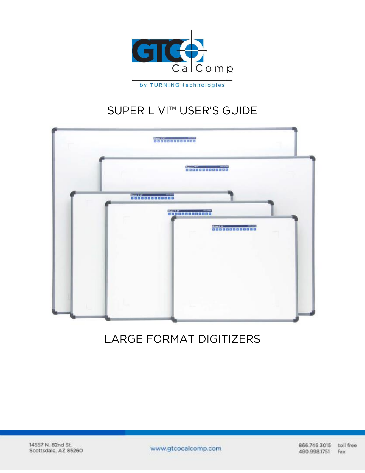
Super L VI belongs to a class of computer input devices called graphics tablets, or
digitizers. A digitizer is an electronic tablet work surface. The position of a transducer, a
handheld cursor or stylus pen, on the work surface of the Super L VI is converted – digitized
– into data for computer processing. Data output from the Super L VI digitizer is in the
form of an X/Y coordinate pair that pinpoints the precise location of the transducer on the
tablet surface. By placing a drawing or sketch on the tablet’s surface and tracing over it,
graphical information can be easily converted into accurate digital information for entry
into the computer. Super L VI digitizers are the next generation of the Super L family of
digitizers that set the standard in large-format digitizing. These high performance tools are
engineered with a state-of-the-art positioning grid to ensure reliability and quality.
Professionals in construction, estimating, CAD, textiles and other fields appreciate the
flexibility and performance of the Super L VI series.
The Super L VI family of large-format digitizers boasts resolutions of up to 2540 lines per
inch, accuracy of 0.010 inch and a wide range of sizes, providing the perfect solution when
the work demands precision data input over a large surface area. A variety of cordless and
corded cursors and stylus pens are available to use with the Super L VI. An integrated
mounting channel allows accessories, such as a plan holder, to be quickly and easily
mounted. The high-productivity Super L VI can be used as both a digitizer and a mouse,
eliminating the need for multiple devices at your computer.
Super L VI works with many graphic, CAD and estimation applications. These applications
use the digitized data from Super L VI to:
Determine the dimensions of objects on drawings and blueprints
Move the pointer on the display screen
Create and manipulate objects in a graphic composition
Trace a drawing or other source material, to create an image on the screen
Select commands or functions from an application menu placed on the tablet
surface
Select items from a pull-down menu on the screen
In order to send data from Super L VI to your digitizing application, the digitizer must be
physically connected to your computer, and it must be able to transmit the data in such a
way that the digitizing application recognizes and understands it.
Page 5

Super L VI 5
Super L VI digitizing tablet
Transducer (corded or cordless pen,
4-button or 16-button cursor)
USB cable
CD-ROM with Windows Drivers and
user’s manual
Registration card
RS-232 with 9-pin connector for serial
connection
Power supply – required only for a
serial installation
Universal mounting brackets
Adjustable table feet
Accessory tray
Plan holder
Before setting up Super L VI, you should determine:
The requirements of the digitizing software application you’re using
Whether your digitizing application requires software drivers to communicate with
Super L VI
The hardware communications connection (USB or Serial) you will be using between
the Super L VI and the computer
When the Super L VI is set up for a serial connection, it must be configured so that it can
send data in a way the application software will recognize and understand. Different
applications have different requirements when interacting with a digitizer. The Super L VI
has been designed to provide the appropriate serial requirements for a wide variety of
graphic, CAD and estimating applications using a simple code system. The SuperSet Menu
located at the top of the Super L VI is used to enter the appropriate code for the software
you are using. Table 1 in the Using the SuperSet Menu section of this manual lists the
SuperSet Codes for a wide variety of applications. All you have to do is input the code for
the application you are using and the Super L VI will be able to communicate properly with
the application software on your computer. Table 2 lists the configuration details for each
SuperSet Code in Table 1.
If for some reason, the communication requirements for your software cannot be found in
the two tables provided in the SuperSet Menu section, the Tablet Configuration Utilities on
the enclosed GTCO CalComp by Turning Technologies CD can be used to configure your
Super L VI so it has the appropriate information it needs to communicate successfully with
your software.
Parts Checklist
Optional Equipment
Page 6
Super L VI 6
What You Will Need to Use the Super L VI
Super L VI is equipped with both a USB interface and an RS-232 serial interface, which
requires an optional RS-232 cable and power supply. It is compatible with most industrystandard PCs. The TabletWorks CD contains drivers provided by GTCO CalComp by Turning
Technologies and is the only software described in this manual. TabletWorks supports
reduced functionality Wintab and TabCon-compatible applications. If you are not sure
which drivers are required, please consult with your application vendor.
A USB connection requires the use of a TabletWorks driver, while a serial connection
requires the use of a TabletWorks driver and/or a custom application program. After
installing the TabletWorks software, the Super L VI will work with all Windows-based
applications as a mouse, in addition to working as a digitizer with Windows-based
applications that are specifically designed for use with digitizers.
PC Requirements
For a USB Installation
Microsoft Windows 98 SE, ME, 2000, XP, Vista, 7 or 8
One available USB port
10 MB of free disk space
Application software that accepts digitizer input via the Wintab API or TabCon API
For an Optional Serial Installation
Microsoft Windows 98, ME, NT 4.0, 2000, XP, Vista, 7 or 8
One available RS-232C serial communication port (Serial signal levels must conform
to EIA RS-232C specifications.)
10 MB of free disk space
Application software that directly accepts digitizer input via the computer’s RS-232C
serial port, or via the Wintab API or TabCon API
Page 7
Overview
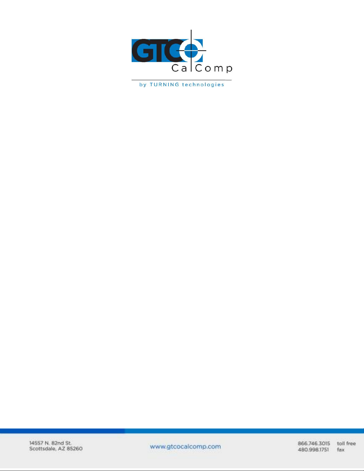
The Super L VI consists of:
Super L VI 7
Active Area
The drawing area – the Active Area – is the portion of the tablet surface designated for
digitizing. Its boundaries are marked at each corner by a right-angle crop mark.
SuperSet Menu
The SuperSet Menu is the row of keys located across the top of the digitizer. It provides a
means of configuring your tablet so that it sends the appropriate information for a serial
connection to the software you’re using on your computer.
Indicator Light
The power/proximity LED in the upper right corner of the Super L VI frame is the Indicator
Light. It remains off when the power is on. However, when the transducer is in prox
(within the range) of the Active Area, the LED is solid green.
Page 8

Super L VI 8
Transducer
Two types of transducers can be used with the Super L VI: pens and cursors. Both are
available in corded and cordless versions. The corded transducers get their power from
the digitizer. Cordless transducers are powered by batteries. They will go into a batterysaving Sleep Mode when no button has been pressed for one to five minutes, depending on
the type of transducer being used. To reactivate a sleeping transducer, press one of its
buttons.
Cursors
The cursor is similar in appearance to a mouse, except that it has an attached lens with
crosshairs for highly accurate detail work. Cursors are available in 4 or 16 button models.
Pens
Each pen is similar in appearance to a ballpoint pen. The pen transducer has three
buttons, two on the side of the barrel and one in the pen tip. Two different types of pens,
identified by a colored ring on the pen barrel, are available for use with the Super L VI. The
cordless Click Tip pen has a light blue ring and the cordless Lite Touch Tip pen, a red ring.
Setting Up Your Super L VI
The instructions below describe how to set up your Super L VI. Before you begin, please
take a moment to fill out and mail the Warranty Registration Card or register your digitizer
on our website at http://www.gtcocalcomp.com/warranty-information.
Preparing the Super L VI
Mounting on the Stand
Place the Super L VI on a table, desk or drafting table. You can also mount Super L VI on a
stand or pedestal. The tablet’s Universal Mounting Brackets attach directly to those stands
that have tilt arms. Stands with tilt pads require right-angle mounting brackets, which are
attached to the tilt pads. The tablet’s Universal Mounting Brackets are then attached to the
right-angle mounting brackets. Center the tablet over the attached Universal Mounting
Brackets and screw the Thumbscrews into the T-Nuts in the mounting channel in the
tablet’s frame.
Page 9
Super L VI 9
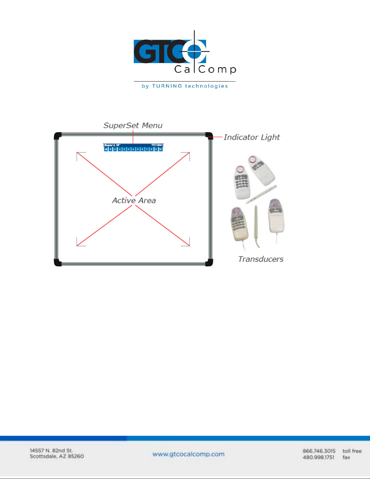
Attaching the Optional Accessory Tray, Plan Holder or Table Feet
Additional T-Nuts have been included in the perimeter mounting channels on the Super L
VI frame. You can position the Plan Holder, Table Feet or Accessory Tray where it is most
convenient for you by attaching it to any one of the available T-Nuts. The following
instructions and the graphic below detail the installation of the Accessory Tray.
Simply slide the Tray Rails into the channel and line up the hole in the tray with the hole in
the T-Nut. Tighten the Thumb Screw to secure the Accessory Tray.
Software Configuration
Software drivers provide the communication bridge between your digitizing software
application and Super L VI. You should install only the drivers necessary for the Super L VI
to work with your application software. If you are not sure which drivers are required,
consult with your application vendor.
Configuring Non-Wintab Applications
Many application programs provide configuration information for specific digitizers. If the
Super L VI digitizer is not listed, you can use the configuration for the GTCO CalComp by
Turning Technologies Digi-Pad Type 5 or Type 5A (T5/T5A), Roll-Up II, CalComp 3400,
DrawingBoard or Summagraphics Microgrid III.
Page 10
Super L VI 10
Installing the TabletWorks Driver
Insert the CD into the CD-ROM drive on your computer. The installer will autoload. If it
does not, click on the Start button on the Windows Task Bar and select Run from the
menu. Type X:\setup.exe (X represents the CD drive letter). Follow the onscreen prompts
to complete the installation.
A TabletWorks icon will display in the System Tray on the Windows Task Bar. Right
click on the icon to display the TabletWorks Menu, which provides access to all the
TabletWorks features.
Hardware Configuration
When you use the USB interface, no hardware configuration is required. When the
optional serial interface is selected, Super L VI must be configured to send data in a format
that is compatible with the application software. Different applications have different
requirements when interacting with a digitizer. The Super L VI is designed to provide the
appropriate serial requirements for a wide variety of graphic, CAD and estimating
applications using a simple code system. The SuperSet Menu on the surface of the Super L
VI is used to enter the appropriate code for the software being used. A table in the Using
the SuperSet Menu section of this manual lists the SuperSet Codes for a wide variety of
applications.
Determine if you have not already, which communication connection you will be using –
USB or the optional serial.
Page 11
Super L VI 11
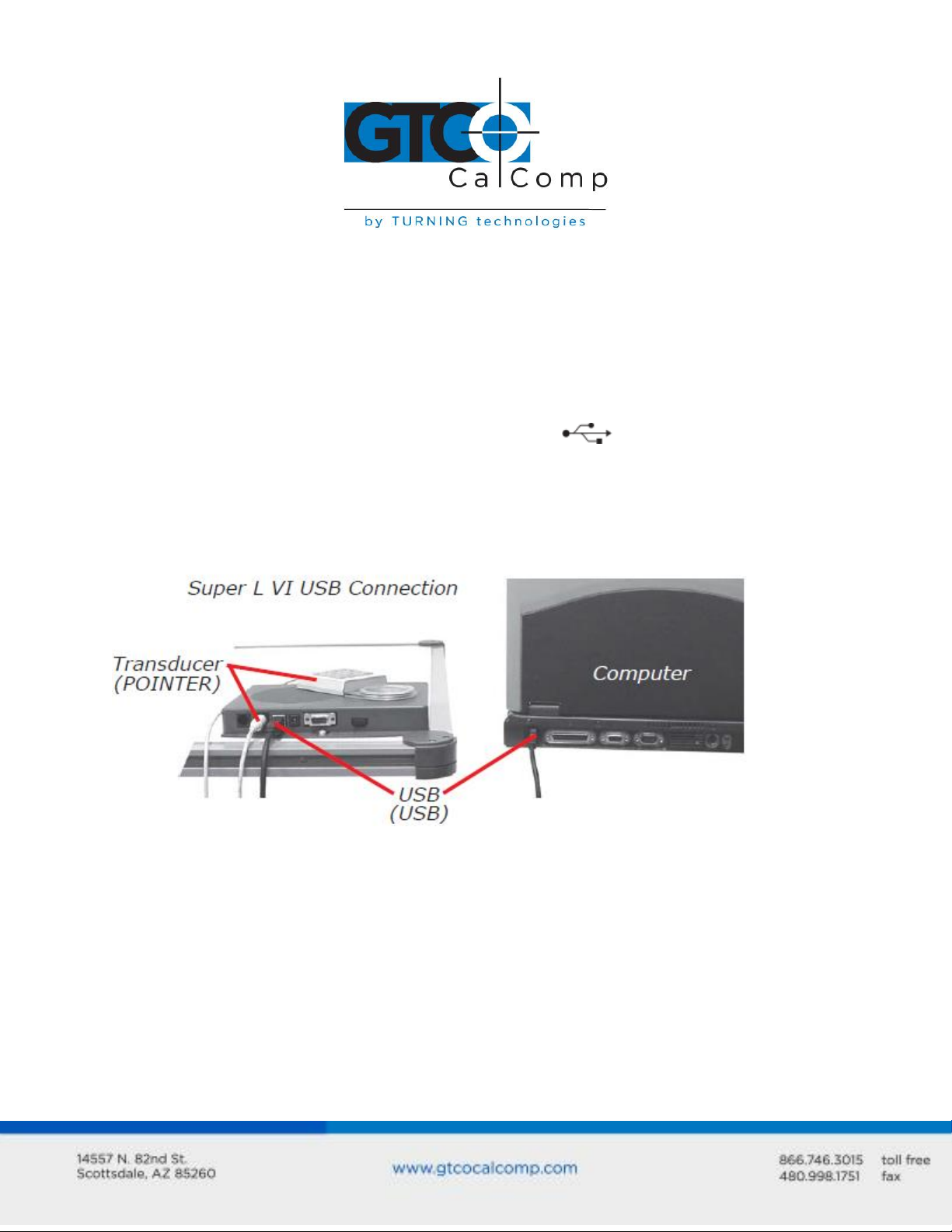
USB Connection
Super L VI USB port connection is USB 1.1 and 2.0 compatible. When the digitizer is
connected to the USB port, Windows will recognize that there is a new device connected. If
Windows displays the Found New Hardware prompt, follow the onscreen instructions to
complete the driver installation.
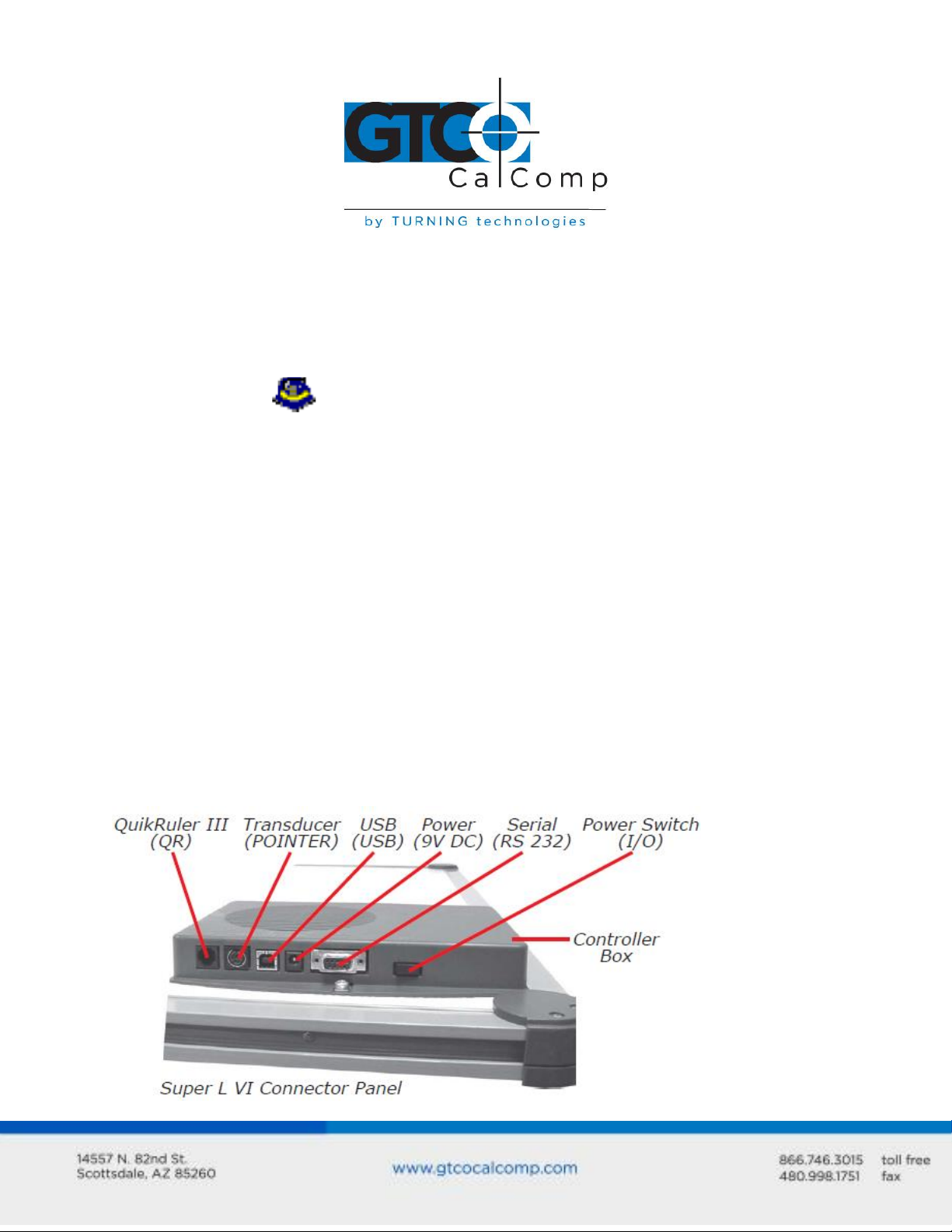
1. Connect the interface cable to the USB jack on the Super L VI Connector Panel. The
connector is keyed and will fit only the correct jack. Do not force it. Attach the other
end of the USB cable to any one of the USB ports on your computer or USB
hub.
2. Turn the power switch on. The green Indicator Light will begin blinking and the
digitizer will beep four short tones, indicating it has power. See the Super L VI Tones
section for a complete table of the Super L VI tones.
NOTE: Power is supplied through the USB port. No additional power source is needed for
this installation.
QuikRuler III™ Connection
The Super L VI has a connection socket for the QuikRuler III. The QuikRuler III is a portable
measuring system that quickly and accurately automates blueprint takeoff and drawing
measurement processes. Contact GTCO CalComp by Turning Technologies for price and
availability.
Page 12

Super L VI 12
Transducer Connection
1. If you are using a corded transducer, connect the cursor or pen to the appropriate
jack on the digitizer’s Connector Panel. The connector is keyed and will fit only the
correct jack. Do not force it.
Optional RS-232 Serial Connection
1. Connect the RS-232 serial cable to the serial jack on the Connector Panel. The
connector is keyed and will fit only the correct jack. Do not force it. Attach the 9-pin
connector of the serial cable to the serial port on your computer.
2. Plug the power supply into an AC outlet. Connect the power supply to the
appropriate jack on the Super L VI Connector Panel. Turn the power switch on. The
green Indicator Light will begin blinking and the digitizer will beep four short tones
(see the Super L VI Tones section for a complete table of Super L VI tones), indicating
it has power.
Tablet Power On
The Super L VI power switch is located at the rear of the tablet on the Connector Panel.
When turned on, the Super L VI’s Indicator Light will begin blinking and four Success tones
will sound.
If you are using a cordless transducer, turn it on by pressing any button on the tool. The
Indicator Light will glow steadily when the transducer is inside the Active Area of the tablet.
When the transducer moves outside the Active Area, the Indicator Light will go off.
Page 13
Super L VI 13
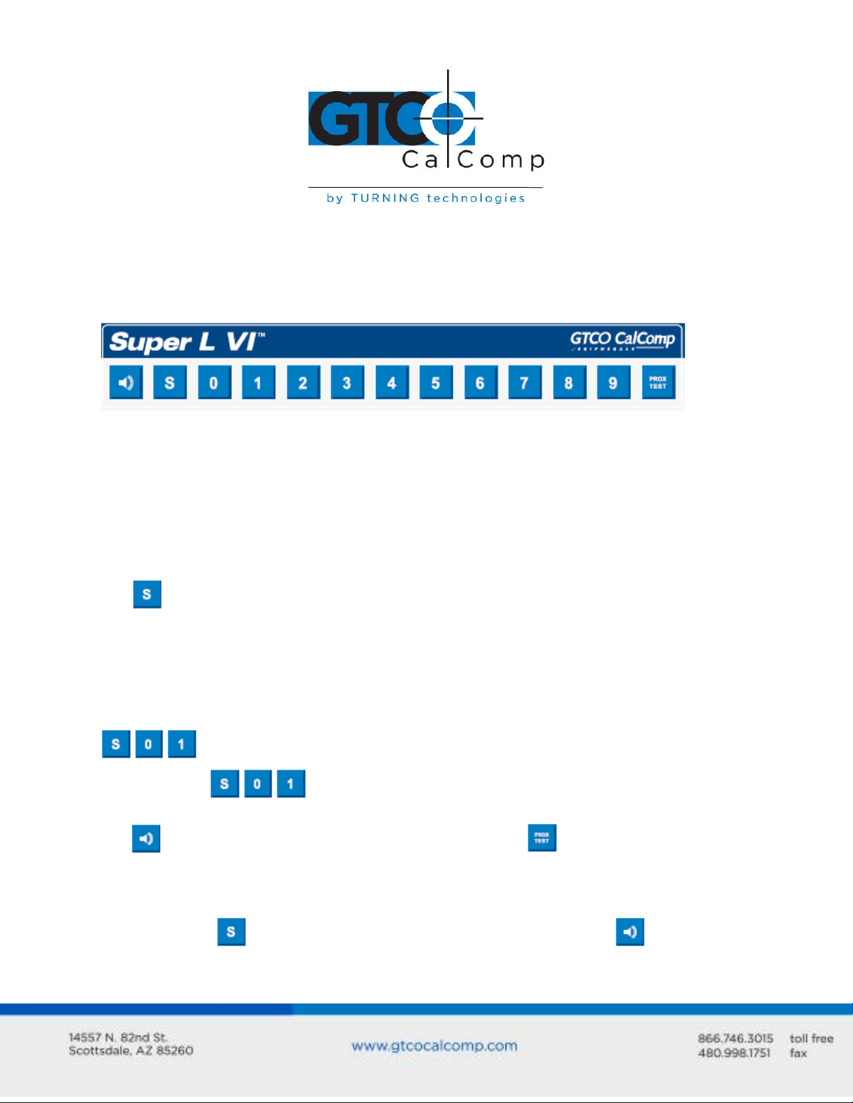
Using the SuperSet Menu (RS-232 Only)
The SuperSet Menu is the row of buttons printed across the top of the digitizer. It allows
you to configure Super L VI to send the appropriate information through an RS-232 serial
connection to the software being used on the computer.
The SuperSet Menu is used to prepare the digitizer to receive specific, detailed custom
configuration information from the Tablet Configuration Utilities for some serial
installations. Use your transducer (pen or cursor) to click on the menu buttons to make
your selections.
In addition, for both serial and USB connections, the SuperSet Menu can be used to reset
the Super L VI, turn the digitizer alarm OFF or ON, and test the grid or Active Area.
The menu button initiates Select Mode. Two-digit numeric codes are entered after
Select Mode is activated.
NOTE: The Select Mode will not work with the USB interface. USB digitizers are used
exclusively with Wintab drivers.
Most software supports Wintab using the TabletWorks drivers, whose SuperSet Code is
on the SuperSet Menu. The Super L VI comes from the factory with the
SuperSet Code pre-configured.
The button toggles the digitizer alarm OFF or ON. The button tests the digitizer
grid in the Active Area.
When using the SuperSet Menu, a tone will sound indicating a successful selection when
you click on the button. Four tones will sound when you select the button. (See
the Super L VI Tones section for a complete table of the Super L VI tones.) The number
Page 14
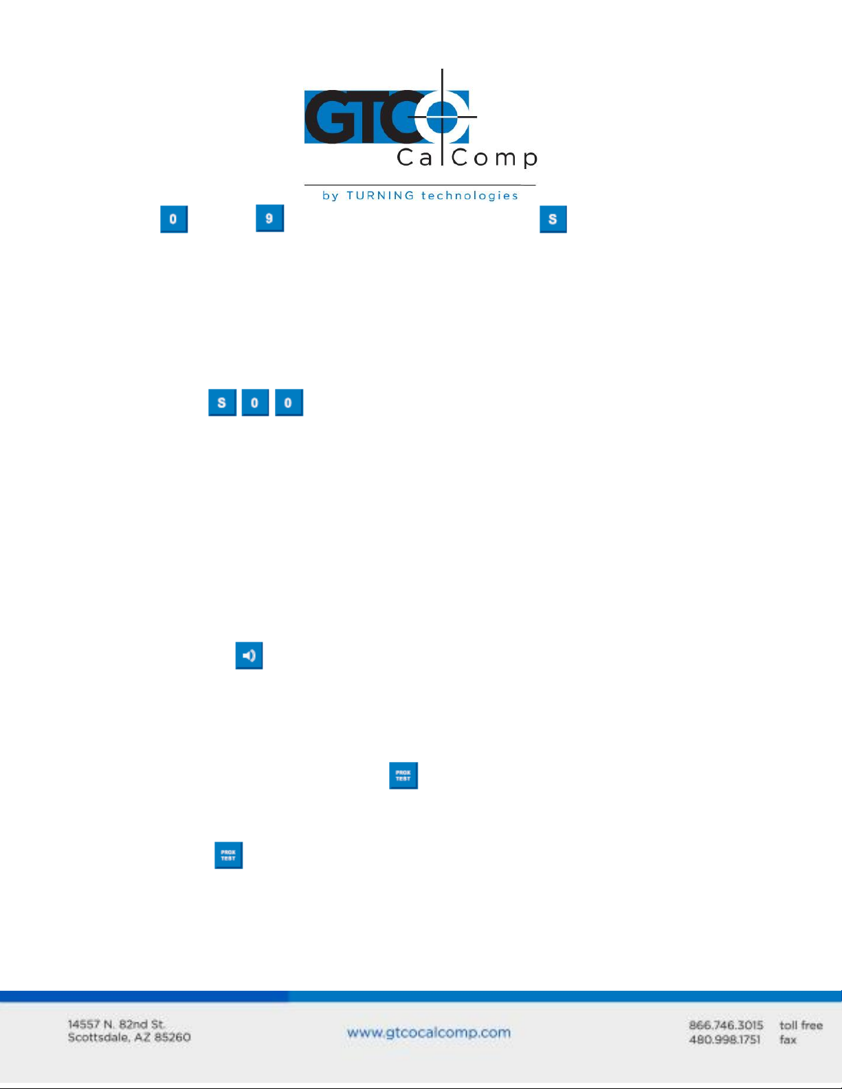
Super L VI 14
buttons through are active only after clicking on the button to activate
Select Mode.
Resetting Super L VI
The Super L VI can be reset by:
Turning off the power switch on the Controller Connector Panel
Unplugging and re-plugging the power supply
Clicking on the SuperSet Menu.
When one of these events occurs, the Super L VI will revert to the configuration that was
last defined. Any remote commands that were active before the reset will be lost.
Turning the Alarm Off and On
You can disable the alarm if you do not want to hear a tone each time the transducer
button is pressed. When the alarm is off, you will still hear diagnostic and menu-related
tones.
To turn the alarm Off or On:
Click on the button to toggle the tones Off or On.
Testing the Active Area
To test the Super L VI grid, or Active Area:
1. Using the transducer, click on the button to activate the test.
2. Move the transducer around in the Active Area. If there is a break in the grid or the
transducer is out of prox, the tablet will beep.
3. Click the button again to end the test.
NOTE: The following is relevant only when connecting via an RS-232 serial installation. USB
does not require configuration.
Page 15
Super L VI 15
Configuring Super L VI for Specific Applications
To configure your Super L VI for use with specific applications:
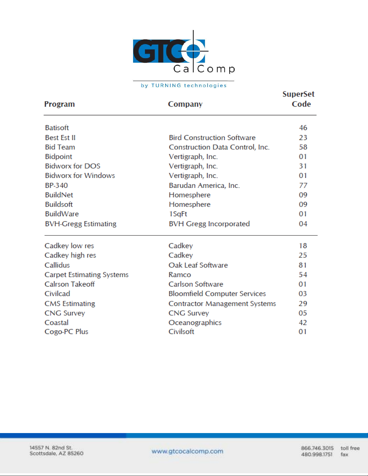
1. In Table 1, find the application program you will be using with your Super L VI. Note
the corresponding SuperSet Code.
If your application program is not listed in Table 1, find the configuration
settings in Table 2 that your application program requires and use the
corresponding SuperSet Code.
If an appropriate SuperSet Code is not listed in Table 2, then use the Tablet
Configuration Utilities to configure your Super L VI.
2. On the SuperSet Menu, click on the button, and then click on the two digits of
the SuperSet Code indicated for your application.
You will hear four short tones after a successful menu configuration.
Example: Configuring for a Specific Application
To configure your Super L VI to operate with Autodesk’s AutoCAD application, you would:
1. Find the entry for AutoCAD in Table 1. The SuperSet Code is .
2. Click on the button on the SuperSet Menu. You will hear one short tone,
indicating the digitizer is in Select Mode.
3. Click on the button on the SuperSet Menu. You will hear one short tone. This
enters the first digit of the SuperSet Code for AutoCAD.
4. Click on the button on the SuperSet Menu. This enters the second digit of the
SuperSet Code for AutoCAD.
You will hear four short tones, indicating that the configuration is complete. The Super L VI
is now configured to operate with AutoCAD. Select Mode is no longer active and you can
begin digitizing.
NOTE: For more information about digitizer software application driver requirements,
please visit the Technical Support section of the GTCO CalComp by Turning Technologies
website.
Page 16
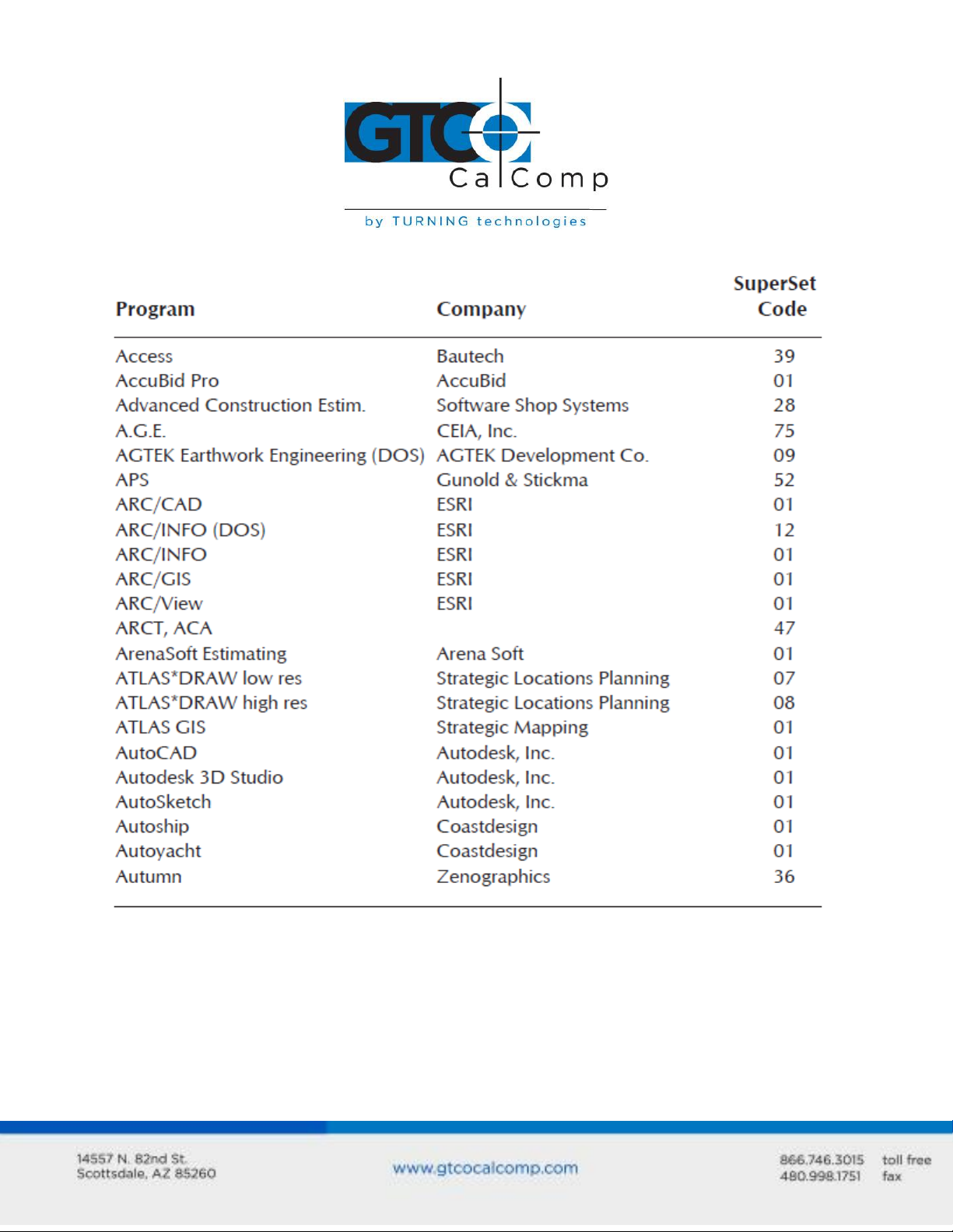
Table 1: SuperSet Menu Codes for Selected Applications
Super L VI 16
Page 17
Super L VI 17
Page 18

Super L VI 18
Page 19

Super L VI 19
Page 20

Super L VI 20
Page 21

Super L VI 21
Page 22

Super L VI 22
Page 23

Super L VI 23
Page 24

Super L VI 24
Page 25

Super L VI 25
Page 26

Table 2: Configuration Details for SuperSet Menu Codes
NOTE: Max = 100 coordinates/second
lpi = lines per inch lpmm = lines per millimeter
Super L VI 26
Page 27

Super L VI 27
Page 28

Super L VI 28
Page 29

Super L VI 29
Page 30

Super L VI 30
Page 31

Super L VI 31
Super L VI Tones
The Super L VI produces an alarm in the form of audio tones to inform you of various
events. The table below describes the kinds of tones you might hear while operating the
digitizer.
Table 3: Super L VI Tones
*Configuration error tones or Diagnostics failed tones indicate a serious problem. If
you hear either of these tones, call GTCO CalComp by Turning Technologies Technical
Support at 1.866.746.3015.
NOTE: You might hear tones produced by the Super L VI which are actually sent by your
application program. (Programs can send commands to the digitizer to turn the audio tone
generator on and off.) If you hear tones during digitizing and they do not correspond to
the tones listed in the table above, they are produced by the application program.
Introduction to the Tablet Configuration Utilities
The Super L VI with its Controller uses the Tablet Configuration Utilities to control baud
rate, data format and other operating characteristics for the RS-232 interface. It is used to
relay configuration information to the Super L VI in cases where Table 1 and Table 2 do not
supply the information or a SuperSet Menu Code for the graphic application software being
used.
Page 32

Super L VI 32
The configuration parameters for the Super L VI are divided into three categories:
Communication Options
Output Format Options
Mode Options
Communication Options
Baud: The rate, in bits/second, at which characters are transmitted across the RS-
232C serial interface. Choices are: 1200, 2400, 4800, 9600, 19200 or 38400.
Data Bits: Data bits represent the actual data being sent from one device to
another. Both devices must be set for the same number of data bits. Choices are:
Seven (7) or Eight (8).
Stop Bits: Each character has one or two stop bits, which tell the receiving device
that a character is complete. The number of stop bits usually does not matter.
Setting for two stop bits instead of one may overcome a mismatch in parity or data
bits. Choices are: One (1) or Two (2).
Parity: One bit can be allocated for parity (parity is a simple error-detecting
scheme). Both devices (sending and receiving) must be set for the same parity –
either odd parity or even parity – or they must be set for no parity. Choices are:
None (N), Even (E) or Odd (O).
Output Format Options
GTCO: Selects GTCO-compatible formats. See Advanced Programing Information in
the Super L VI Online Help for greater detail on GTCO format structure. Choices are:
Binary or ASCII.
CalComp: Selects CalComp-compatible formats. See Advanced Programming
Information in the Super L VI Online Help for greater detail on CalComp format
structure. Choices are: Binary, ASCII 1, ASCII 2, ASCII 3 or ASCII 4.
Summa: Selects Summagraphics-compatible formats. See Advanced Programming
Information in the Super L VI Online Help for greater detail on Summagraphic format
structure. Choices are: Binary or ASCII.
Page 33

Super L VI 33
ASCII formats can be modified by including or excluding a button code, decimal point,
carriage return or line feed, depending on whether GTCO, CalComp or Summa formats
have been selected.
Button: Defines whether the Pushbutton (Pb) value is included in the ASCII output
report. This option is available only with GTCO formats. Choices are: Include or
Exclude.
Space: Defines whether the Space (Sp) character (hex 20) is included in the ASCII
output report as a delimiter between the X and Y coordinate values. This option is
available only in GTCO formats. Choices are: Include or Exclude.
Decimal: Defines whether the period character (hex 2E) is included in the ASCII
output report between the units and tenths digits. This option is available only in
Summagraphics formats. Choices are: Include or Exclude.
Return: Defines whether the Carriage Return (CR) character (hex 0D) is included in
the ASCII output report as a terminator. This option is available in GTCO and
Summagraphics formats. Choices are: Include or Exclude.
Line Feed: Defines whether the Line Feed (LF) character (hex 0A) is included in the
ASCII output report as a terminator. This option is available in GTCO, CalComp and
Summagraphics formats. Choices are: Include or Exclude.
Mode Options
Mode: Defines how output reports are sent from the digitizer. Choices are: Point,
Line, Continuous, Line Incremental or Continuous Incremental.
Rate: Determines how fast output reports will be transmitted from the digitizer.
Choices are: 12, 50 or 100 reports per second.
Resolution: The smallest reported value returned by the digitizer. Choices are:
1000 lpi, 2000 lpi, 4000 lpi, 40 lpmm, 100 lpmm or 150 lpmm.
See the Advanced Programming Information section in the Super L VI Online Help at
www.gtcocalcomp.com for more details.
Page 34

Super L VI 34
Using the Tablet Configuration Utilities
If your application is not represented in the SuperSet Menu and does not have a SuperSet
Code or if a different configuration is required, you can use the Tablet Configuration
Utilities to structure the Super L VI. The Tablet Configuration Utilities replace the 24
switches that were associated with older GTCO CalComp by Turning Technologies digitizers
and the Custom Configuration Menu Card used with the Super L II Plus.
To Configure the Super L VI with the Tablet Configuration Utilities:
1. Make sure the Super L VI is plugged into a Serial Port, powered on and all the tablet
drivers have been uninstalled or disabled.
2. Install the Tablet Configuration Utilities from the Select Utility Software to Install
section on the TabletWorks CD, or download them from www.gtcocalcomp.com.
3. After installation is complete, run the Tablet Configuration Utilities from the
Programs list under GTCO CalComp by Turning Technologies TCU.
4. The Tablet Configuration Utilities will begin searching the Serial Ports for a
supported tablet.
a. If the tablet is found, information about the tablet will display under Device
Info near the bottom of the screen.
b. If the tablet is not found, a message will appear under Device Info near the
bottom of the screen.
i. If Wintab files were found, it is possible that the TabletWorks driver
has the Serial Port open.
ii. If the Serial Port is open by another application, it will not be
displayed under System Info. Close any application or uninstall any
driver that is using the Serial Port and select Refresh System Info from
the File dropdown list at the top of the screen. Click on the Serial Port
icon under System Info to search that Serial Port.
NOTE: The Tablet Configuration Utilities can use the TabletWorks driver to test the tablet,
but it must be communicating directly with the tablet, via the Serial Port, in order to
configure it.
5. Once the Super L VI has been found on a Serial Port, select Advanced Configuration
from the Options dropdown list at the top of the screen.
a. If Advanced Configuration is not an option, make sure Wintab Compatible
Driver is not listed under Device Info.
Page 35

Super L VI 35
6. Select a predefined through , SuperSet Code, or select one of the
User Defined through , SuperSet Codes to customize.
a. User Defined ( through ) SuperSet Codes are initially read
from the tablet when the Advanced Configuration screen opens. This is to
prevent loss of custom settings. Selecting Read Current Settings from the
Options menu will:
i. Read the Power-Up settings and User Defined SuperSet Codes from
the tablet.
ii. Overwrite all Custom Settings not yet saved to the tablet.
b. Restore Factory Settings from the Options menu will prompt for:
i. Power-Up settings reset to factory default and set current.
ii. User Defined SuperSet Codes cleared and reset to factory default.
7. After making your selections, choose one of the following from the File menu at the
top of the screen.
a. Save Temporary Settings will configure the tablet as shown until the tablet
is powered off, reset or another SuperSet Code is selected.
i. After saving temporary settings, select File/Exit to test with other
applications. This will leave the tablet configured to the temporary
settings selected and close the Serial Port, enabling other applications
to communicate with the tablet.
b. Save Power-Up Settings will configure the tablet as shown. Every time the
tablet is powered off and back on or reset, it will restore these settings.
c. Save Custom Settings will reconfigure all nine of the tablet’s User Defined
SuperSet Codes to the settings specified in the corresponding SuperSet Code
dropdown list.
i. You can click on the SuperSet Menu buttons on the tablet using the
tablet’s cursor to activate these configurations:
plus through .
8. When you have finished, select Exit or Close from the File menu.
a. Exit will close the Tablet Configuration Utilities.
b. Close will exit the Advanced Configuration Screen and return to the Tablet
Configuration Utilities window.
Page 36

Super L VI 36
Learning the Basics
You will find that using your DrawingBoard VI tablet is as easy or easier, than using a
mouse. The DrawingBoard VI transducers are more accurate than a mouse, giving you
greater control over your movements.
Using the Transducer
The transducer does not need to be in contact with the tablet surface in order for the tablet
to sense its presence. It can be detected up to ½” above the Active Area. When the
transducer is in the zone above the surface of the digitizer, it is referred to as being in prox.
The Indicator Light will go from a blinking green light to a solid green light when the
transducer is in prox of, or touching, the tablet’s surface. The in prox zone allows you to
trace through materials placed on the digitizer’s surface, such as drawing or a book. Before
using the transducer, be sure that Sleep Mode is turned off by pressing a button, or in the
case of the pen, touching the tip of the tablet’s surface.
Using the Cursor
When you use the cursor, the intersection point of the crosshairs on the lens identifies the
point you are selecting. The crosshairs are etched on the bottom of the lens to increase
accuracy. For maximum precision, look through the lens from a position directly over it.
Button 0, the yellow button, is used as the pick, or left mouse, button. All other buttons are
defined by the TabletWorks software, or through your own software application.
Using the Pen
There are two variations of pens: the click tip and the lite touch tip. On both pens, the pen
tip is Button 0 and is used as the pick, or left mouse, button. The lower side button is
Button 1 and the upper side button is Button 2.
The functions these buttons provide are defined through the TabletWorks software, or
through your own software application.
Click Tip Pen
The click tip pen is available in both corded and cordless versions. It is primarily used for
tracing and menu picking. To use the click pen, press down until you feel the tip click.
Page 37

Super L VI 37
Lite Touch Pen
The lite touch pen is available only in the cordless version. It is similar to the click tip pen,
except that it calls for, as the name implies, a lighter touch, without the click.
Learning Basic Movements
Clicking and Double-Clicking
Clicking is the action of making a selection. You may be selecting a key on the digitizer
surface or making a selection from your computer monitor. To click, place the transducer
or move the screen pointer using the transducer, to the item to be selected. Tap the pen
or press Button 0 on the cursor. A double-click requires you to quickly tap the pen or press
the button two times, while the tool remains in the same place. You can also double-click
by pressing the pen or cursor button that has been defined as a double-click button (see
TabletWorks Help).
Dragging
Dragging is the action of moving the transducer during a selection. To drag, click on an
object, but instead of lifting the pen tip or releasing the cursor button, hold it down while
moving the transducer, or corresponding object on the screen, to the desired new location.
Caring for the Tablet and Transducer
Follow these precautions at all times to avoid damaging your Super L VI:
Avoid discharging static electricity to the tablet.
Do not place heavy objects on the tablet surface.
Do not use sharp objects; such as compasses or knives, on the tablet surface.
Do not use the tablet surface for any purpose other than drawing, tracing or
digitizing.
Do not drill holes on any part of the digitizer or controller.
Cleaning the Tablet
To clean the tablet’s surface, use a soft, non-abrasive cloth. Hardened dirt can be removed
with a slightly dampened cloth. Do not clean pencil lines with a soft cleanser or pencil
eraser. This could create an undesirable shiny spot on the tablet’s surface that cannot be
removed.
Page 38

Super L VI 38
To replace the pen tip, grasp the tip and pull
straight out (see figure). Insert the new tip
and press until it clicks into place.
Cleaning the Cursor
To clean the cursor body, use a mild cleanser. Do not spray the cleanser directly on the
cursor – instead, dampen a soft cloth with a mixture of water and the cleanser. Clean the
cursor reticles with alcohol.
Replacing the Pen Tip
Replacing the Cordless Pen Batteries
The pen requires two 393 silver oxide batteries. The average battery life is 200 hours.
Page 39

Super L VI 39
To replace the batteries:
1. Unscrew the pen cap. Hold the
pen from the bottom and gently
slide off the pen cover to expose
the batteries.
2. Remove the old batteries by
turning the pen over and gently
tapping it, letting the batteries
fall into your other hand.
3. Insert the new batteries as they
are shown in the figure above (+
towards pen tip).
4. Replace the pen cover and screw
the pen cap onto the pen.
NOTE: When you replace the pen batteries, the pen will reset to the default frequency. If
you changed the frequency of the pen before replacing the batteries, you will need to do so
again after replacing the batteries (see the Reducing Monitor Interference section in
Troubleshooting).
Replacing the Cordless Cursor Batteries
The cordless cursor requires two AAA batteries. The average battery life for the cursor
batteries is 2,000 hours.
Page 40

Super L VI 40
To replace the batteries:
1. Place the cursor face down in the
palm of your hand. Use a Phillips
screwdriver to remove the two
screws located on the bottom of
the cursor (see figure). Remove
the cursor base.
2. Remove the old batteries from the
battery casings.
3. Place the new batteries in the
casings, matching the polarity of
each battery with the markings on
the connector strips (match + to
+).
4. Reposition the cursor base.
Replace the screws with the
Phillips screwdriver.
NOTE: When you replace the cordless cursor batteries, the cursor will reset to the default
frequency. If you changed the frequency of the cursor before replacing the batteries, you
will need to do so again after replacing the batteries (see the Reducing Monitor
Interference section in Troubleshooting).
Troubleshooting Guide
GTCO CalComp by Turning Technologies wants your experience with Super L VI to be a
successful one. If you ever encounter a problem, please follow the steps below:
1. Install properly first.
This troubleshooting guide assumes you have already correctly installed your Super L VI
according to the detailed instructions in the Installing Your Super L VI section. If you have
not followed the step-by-step instructions in that section, do so now.
Page 41

Super L VI 41
2. Read the topics below to check for a solution to your problem. Work through
the troubleshooting flowcharts on the following pages in this troubleshooting
guide. The Tablet Configuration Utilities application referenced there can be
found in Super L VI Online Help.
Record any unusual observations. Your notes will be useful if you need assistance from
GTCO CalComp by Turning Technologies.
3. If your system still doesn’t work.
Call GTCO CalComp by Turning Technologies Technical Support at 1-866-746-3015
(in the U.S. or Canada) or email us at gtco.support@gtcocalcomp.com. Outside the
U.S. or Canada, contact your local GTCO CalComp by Turning Technologies office or
dealer. Be prepared to discuss the observations you made while troubleshooting.
Reducing Monitor Interference
If you are experiencing monitor interference with your tablet, you can reduce the
interference by changing the frequency your transducer uses. This can be done only for
transducers that support changing the frequency.
Transducers with the following FCC ID numbers support two frequencies: ECPPPP, ECPPP2,
ECPPLTP, ECPPCURSOR4, ECPPCURSOR16 and ESPPCURSORII. Transducers with FCC ID
numbers other than those listed must have their frequency changed by GTCO CalComp by
Turning Technologies.
Changing the Frequency of the Cordless Cursor
1. Place the cursor on the tablet surface.
2. Press Buttons 1 and 2 simultaneously and hold for approximately three seconds.
3. The cursor turns itself off. You will know the cursor is off when the Indicator Light
on the tablet begins blinking.
4. The cursor turns on again at the new frequency. You will know the cursor is on
when the Indicator Light glows steadily.
To return to the default frequency, repeat the above process. When you replace the cursor
batteries, the cursor is automatically reset to the default frequency.
Page 42

Super L VI 42
Changing the Frequency of the Cordless Pen
Press both side buttons and the tip simultaneously and hold for approximately three
seconds. To return to the default frequency, repeat the above process. When you replace
the pen batteries, the pen resets to the default frequency.
Tablet Checklist
Is the tablet power supply (used only with the serial connection to the computer)
plugged into the digitizer and into a live outlet?
Is the tablet power switch on?
Does the Indicator Light glow steadily when the transducer is in prox inside the
Active Area? Does the Indicator LED go out when the transducer is outside the
Active Area?
The Indicator Light will be off if the transducer has gone into Sleep Mode. Press any
button on the transducer to activate it. If the transducer is in the Active Area and
the Indicator Light remains off, change the transducer’s battery.
Are all cable connections seated properly?
Is the communications cable (either USB or serial) connected to both the digitizer
and the computer? Check that the cable is connected to the serial port specified in
your software package.
Is the transducer cable connected to the digitizer?
Is the tablet set up according to the software recommendations?
Are any of the connector cables or receptacles damaged? Check for bent pins, cut
insulation and loose wires.
Computer Checklist
Is the computer plugged into a live outlet? Did you turn on the computer?
Does the computer work with any of your software? Try one of your other
programs. If the computer has a diagnostic diskette, use it.
Is your software package installed correctly?
If your communications connection is USB, does the USB port work? If serial, does
the serial port work? The only way to test the port without special equipment is to
reinstall something that has worked in the past and see if it still works.
Have there been any recent electrical storms in your area that may have damaged
your equipment?
Page 43

Super L VI 43
Software Checklist
Does the tablet work with some software?
If your tablet currently works with some software packages, you know that the tablet, USB
or serial port and computer work.
Even if the software package you are trying to install and the software that is
working both support the same tablets, it does not always mean that you can use
the same tablet settings. The output format may be the same, but the
communications protocol, resolution, operating mode and data rate may be
different. Check your software’s requirements.
Call the software manufacturer. Perhaps the software package has a problem with
another component of your system.
Did the software work in the past?
If the software package worked with the tablet in the past, then the problem lies with the
new set up.
Check all the connectors. Is the tablet still plugged into the same port? If yes, reset
the tablet by unplugging and re-plugging the power supply and restart the software.
Did you reset or power down the computer?
During reset and power on, the computer can send meaningless characters out the
serial port and this can disable the tablet. Reset the tablet again.
Have you installed any new software or hardware? Remove it from your system and
see if the problem goes away.
Did you move any cables?
If you are using a PC, did the new software alter your AUTOEXEC.BAT file?
Have you updated the software or its drivers?
Are you loading another mouse driver?
Did you reinstall the software, perhaps after a problem with your hard drive?
Double check your installation procedure and the driver you selected.
Reinstall the software from its master diskettes. The program files may have been
corrupted.
Page 44

Troubleshooting Chart
Problem
Cause
Solution
Frozen screen pointer
Screen pointer appears to
shake or jitter
Transducer is in Sleep Mode.
Menu Strip is in
Configuration Mode.
Tablet plugged into the
wrong serial port on the
computer.
Tablet not powered
correctly.
Batteries low in transducer.
Software application set up
incorrectly.
Another device is connected
to a COM port that shares
the same IRQ as the tablet
COM port (i.e., your tablet is
connected to COM1 IRQ4
and your modem is
connected to COM3 IRQ4).
Tablet is set too close to the
screen monitor.
Tablet’s frequency setting
Press any button on the
transducer.
If the configuration light is
on, click on the Config/Exit
key on the Menu Strip.
Is the serial port being used
correctly identified in your
software application?
Check that the power cable
is installed correctly.
Replace the batteries in the
transducer.
Check that the tablet is
identified in your software
application.
Move one of the devices to
another COM port. Contact
your system manufacturer
for assistance in relocating
the device.
Move the tablet farther away
from the screen.
Alternate the transducer’s
The following table lists common Super L VI problems, their causes and their solutions.
Super L VI 44
Page 45

Unable to use the entire
tablet surface
may conflict with the display.
Incorrect format selected.
Software application set up
incorrectly.
frequency. (See the Reducing
Monitor Interference section.)
Check your selections in the
Menu Strip.
Check that the tablet is
identified in your software
application.
Procedure A: Begin Troubleshooting
Super L VI 45
NOTE: This procedure should only be used to troubleshoot serial connections.
Page 46

Super L VI 46
Procedure B: Troubleshooting
Page 47

Super L VI 47
Page 48

Super L VI 48
Returning your Tablet for Repair
If you believe you have a defective tablet, first see all topics in this section (above) and visit
our website at www.gtcocalcomp.com for the latest support information.
If you’re still unable to properly operate your digitizer system, please call Technical Support
at 1.866.746.3015 or email us at gtco.support@gtcocalcomp.com.
Technical Support will assist you in determining if your tablet is defective and will help you
obtain a Return Merchandise Authorization (RMA) number. Important: Please do not
return your product without first discussing the issue with, and receiving an RMA from, a
GTCO CalComp by Turning Technologies Technical Support Specialist.
Repackaging for Shipment
Whenever you ship electronic equipment, try to ship it in its original packing materials.
Because packing materials are static-charged, you should ship the cursor or any extra
electronics boards inside approved antistatic plastic bags. If you are shipping the tablet or
accessories to a GTCO CalComp by Turning Technologies Service Center for repair, attach a
tag to the equipment with the following information:
Model number
Serial number
Maintenance contract number (if applicable)
Return Merchandise Authorization number
Detailed description of the problem
Regulatory Statements and Warranty
Radio and Television Interference
The user is cautioned that any changes or modifications not expressly approved by the
party responsible for compliance could void the user’s authority to operate the equipment.
This equipment has been tested and found to comply with the limits of a Class B digital
device, pursuant to Part 15 of the FCC rules. These limits are designed to provide
reasonable protection against harmful interference in a residential installation. This
equipment generates, uses and can radiate radio frequency energy and, if not installed and
used in accordance with the instructions, may cause harmful interference to radio
communications. However, there is no guarantee the interference will not occur in a
particular installation. If this equipment does cause harmful interference to radio or
Page 49

Super L VI 49
television reception, which can be determined by turning the equipment off and on, the
user is encouraged to try to correct the interference by one or more of the following
measures:
Reorient or relocate the receiving antenna.
Increase the separation between the equipment and the receiver.
Connect the equipment into an outlet on a circuit different from that to which the
receiver is connected.
Reorient or coil cables.
Consult the dealer or an experienced Radio/TV technician for help.
NOTE: Any cables the user adds to the device must be shielded to be in compliance with
the FCC standards. Any unauthorized modification to this device could result in the
revocation of the end user’s authority to operate this device.
Canada
This digital apparatus does not exceed the Class B limits for radio noise emissions from
digital apparatus as set out in the radio interference regulations of the Canadian
Department of Communications.
Le present appareil numérique n’emet pas bruits radioelectriques depassant
les limites applicables aux appareils numériques de Classe B prescrites dans
le réglement sur le brouillage radioelectrique edicte par le Ministere des
Communications du Canada.
Page 50

Super L VI 50
Page 51

Japan
Super L VI 51
European Union Emission Directive
This product is in conformity with the protection requirements of EU Council Directive
89/366/ECC on the approximation of the laws of the Member States relating to
electromagnetic compatibility.
This product has been tested and found to comply with the limits for Class B Information
Technology Equipment according to CISPR 22/European Standard EN55022. The limits for
Class B equipment were derived for typical industrial environments to provide reasonable
protection against interference with licensed communication devices.
European Union WEEE Directive
The manufacture of this equipment required the extraction and use of natural resources.
It may contain hazardous substances that could impact health and the environment.
In order to avoid the dissemination of the hazardous substances into the
environment and to diminish the pressure on our natural resources, GTCO CalComp
by Turning Technologies encourages you to return this product to the appropriate
take-back system facility. These facilities reuse or recycle most of the materials in
this equipment in a responsible way.
The crossed-out wheeled bin symbol below invites you to use these take-back
systems.
If you need more information about the collection, reuse and recycling systems in
your area, please contact your local or regional waste authority.
Further information about the responsible end-of-life management of this and other
GTCO CalComp by Turning Technologies products is available on our website at
www.gtcocalcomp.com.
Page 52

Bescheinigung des Herstellers/Importeurs
Heirmit wird bescheinigt, dass der/die/das
Super L VI
(Geraet, Typ, Bezeichnung)
im Uebereinstimmung mit den Bestimmungen der
Super L VI 52
Vfg 1046/1984
(Amtsblattverfuegung)
Funk-Entstort ist.
Der Deutschen Bundespost wurde das Inverkehrbringen dieses Geraetes angezeigt und die
Berechtigung zur Ueberpruefung der Serie auf Einhaltung der Bestimmungen eingeraumt.
GTCO CalComp by Turning Technologies, Inc.
(Name des Herstellers/Importeurs)
Dieses Geraet wurde einzeln sowohl als auch in einer Anlage, die einen normalen
Anwendungsfall nachbildet, auf die Einhaltung der Funkentstoerbestimmungen
geprueft. Es ist jodoch moeglich, dass die Funkentstoerbestimmungen unter
unguenstigen Umstaenden bei anderen Geraetekombinationen nicht eingehalten
werden. Fuer die Einhaltung der Funk-entstoerbestimmungen seiner gesamten Anlage,
in der dieses Geraet betrieben wird, ist der Betrieber verantwortlich. Einhaltung mit
betreffenden Bestimmungen kommt darauf an, dass geschirmte Ausfuhrungen
gebraucht werden. Fuer die beschaffung richtiger Ausfuhrungen ist der Betrieber
verantwirtlich.
Page 53

Super L VI 53
Limited Warranty for Super L VI
GTCO CalComp by Turning Technologies, Inc. warrants these products to be free from defects in
material and workmanship under the following terms. Complete and return the enclosed warranty
registration card to ensure that your products are covered with this warranty.
Coverage
Parts and labor are warranted for two (2) years from the date of the first consumer purchase for the
digitizer tablet, controller, transducers and tablet accessories. Power supply and cables are also
warranted for one (1) year. This warranty applies to the original consumer purchaser only.
Within the European Union, the warranty period is two (2) years, as mandated by the EU. Contact
your local dealer or distributor for additional warranty information.
Warranty is only valid if original consumer’s purchase or lease date is less than or equal to six
months from the original GTCO CalComp by Turning Technologies sale date. This information will
be captured by the system serial number and confirmed by the reseller’s purchase order.
A nominal Warranty Handling Fee will be charged after the first 90 days of use and calculated from
the date of original consumer purchase. This payment may be made by Visa, MasterCard or
American Express. A copy of the sales receipt or invoice will be required for warranty verification.
Conditions
Except as specified below, this warranty covers all defects in material or workmanship in the
products. The following are not covered by the warranty:
1. Any product on which the serial number has been defaced, modified or removed (if
applicable).
2. Damage, deterioration or malfunction resulting from:
a. Accident, misuse, abuse, neglect, fire, water, lightning or other acts of nature,
unauthorized modification for any purpose, unauthorized product modification, or
failure to follow instructions supplied with the product.
b. Repair or attempted repair by anyone not authorized by GTCO CalComp by Turning
Technologies.
c. Any damage in shipment of the product (claims must be presented to the carrier).
d. Any other cause which does not relate to a manufacturing defect.
3. Any product not sold or leased to a consumer within six months of GTCO CALCOMP BY
TURNING TECHNOLOGIES original sale date.
GTCO CalComp by Turning Technologies will pay all labor and material expenses for covered items,
but will not pay for the following:
1. Removal or installation charges.
Page 54

Super L VI 54
2. Costs for initial technical adjustments (set up), including adjustment of user controls.
3. Certain shipping charges. (Payment of shipping charges is discussed in the next section of
this warranty.)
4. Packaging costs. (Customers should keep their boxes.)
Warranty Service Procedures
1. To obtain service on your GTCO CalComp by Turning Technologies product, contact the
Technical Support Department to receive a Return Material Authorization Number (RMA#)
and shipping instructions by calling: 1-866-746-3015.
2. Ship the product to GTCO CalComp by Turning Technologies with the RMA# marked clearly
on the outside of the box. Without a clearly marked RMA# on the shipping box, GTCO
CalComp by Turning Technologies reserves the right to refuse the shipment.
3. Although you must pay any shipping charges to ship the product to GTCO CalComp by
Turning Technologies for warranty service, GTCO CalComp by Turning Technologies will pay
the return shipping charges for ground shipment. Other shipping options are available at an
additional fee.
4. Whenever warranty service is required, the original dated sales invoice (or a copy) must be
presented as proof of warranty coverage and should be included in shipment of the product.
Please also include your name, address, telephone number, fax number, email address and
a description of the problem.
5. If GTCO CalComp by Turning Technologies determines that the unit is not defective within
the terms of the warranty, the consumer shall pay the cost of all freight charges, as well as
any repair charges.
Technical Support
Web-based Technical Support is available free of charge at: www.gtcocalcomp.com, where current
driver releases, as well as comprehensive technical support, troubleshooting, Technical Bulletins and
FAQs can be found.
Telephone Technical Support is available free of charge to the original consumer for a period of 90
days from the date of purchase of the product. Please contact our Technical Support Department
at: 1-866-746-3015 or fax your request to: 480.998.1751.
Disclaimer of Unstated Warranties
The warranty printed above is the only warranty applicable to this purchase. ALL OTHER
WARRANTIES, EXPRESS OR IMPLIED, INCLUDING, BUT NOT LIMITED TO, THE IMPLIED WARRANTIES
OF MERCHANTABILITY AND FITNESS FOR A PARTICULAR PURPOSE ARE DISCLAIMED. Assuming the
warranty above stated is otherwise applicable, it is expressly understood and agreed that GTCO
CalComp by Turning Technologies sole liability whether in contract, tort, under any warranty, in
negligence or other shall be for the repair or replacement of the defective parts and under no
circumstances shall GTCO CalComp by Turning Technologies be liable for special, indirect or
consequential damages. The price stated and paid for the equipment is a consideration in limiting
GTCO CalComp by Turning Technologies liability.
Page 55

Super L VI 55
Notice
Some states and provinces do not allow the exclusion or limitation of incidental or consequential
damages, so the above exclusion may not apply to you. This warranty gives you specific legal rights,
and you may have other rights, which vary from state to state, or province to province.
To obtain service on your GTCO CalComp by Turning Technologies product, call our Technical
Support Department at: 1-866-746-3015 or fax us at (480) 998-1751. We can also be contacted
through our website at www.gtcocalcomp.com (in US); at EUOffice@gtcocalcomp.com (in Germany);
at infos@calcomp.fr (in France).
Important!
All products returned to GTCO CalComp by Turning Technologies for service must have prior
approval in the form of a Return Merchandise Authorization Number (RMA#), which can be obtained
by calling the Technical Support Department.
Page 56

Super L VI 56
Corporate Headquarters
14557 N. 82nd Street
Scottsdale, Arizona 85260
Tel: 1-866-746-3015
Support: 1-866-746-3015
Fax: 480-998-1751
Support: 1.866.746.3015
Copyright© 2014 GTCO CalComp by Turning Technologies, Inc.
Super L VI is a trademark of GTCO CalComp by Turning Technologies, Inc.
All other products and company names are the trademarks or registered trademarks of
their respective owners.
The information contained in this document is subject to change without notice. GTCO CalComp by
Turning Technologies assumes no responsibility for technical, or editorial errors, or omissions that may
appear in this document, or for the use of this material. Nor does GTCO CalComp by Turning
Technologies make any commitment to update the information contained in this document. This
document contains proprietary information which is protected by copyright. All rights reserved. No part of
this document can be photocopied or reproduced in any form without the prior, written consent of GTCO
CalComp by Turning Technologies, Inc.
 Loading...