

Page 1
Bit Pad Two 1
Chapter 1
Chapter 2
Chapter 3
Chapter 4
Operation Overview
Configuration Parameters
Section A: Proximity Transmission
Section B: Remote Control
Section C: Baud Rate
Section D: CTS Handshaking
Section E: Hardware Interface
Connector Pin Assignments
Signal Levels
Section F: Report Format and Cursor Output Codes
Bit Pad Two Packed Binary Format
Bit Pad ASCII BCD Format
Guidelines for Writing a Software Driver
Operating Characteristics and Commands
Section A: Controlling the Report Flow and Content
Primary Modes
Stream Mode, Switch Stream Mode and Report Rate
Point Mode
Remote Request Mode
Modifiers
Absolute Mode
Relative Mode
Increment Mode
Section B: Combining Characteristics
Section C: Other Commands
Resolution Send Configuration
Transmission Control
3
6
6
7
7
7
8
8
9
10
10
12
13
17
18
18
18
21
21
21
21
22
23
25
26
27
27
Table of Contents
Page 2

Bit Pad Two 2
Chapter 5
Chapter 6
Appendix A
Appendix B
Appendix C
Appendix D
Reset
NOP (No Operation)
Checking the Data Tablet
Section A: Self-Test Diagnostic Function
Section B: In Case of Failure
Operating Environment, Installation, Care and Service
Section A: Operating Environment
Temperature and Humidity
Power
Section B: Unpacking and Installation
Unpacking
Installation
Changing the Stylus Refill
Section C: FCC Considerations
Section D: Care and Cleaning
Section E: Service
Specifications
Physical Description
Power Requirements
Optional Power Supplies
Material and Cosmetics
Operating Specifications
ASCII Conversion Chart
How the Bit Pad Two is Different from Bit Pad One
Quick Reference Sheet of Commands and Switch Settings
28
28
29
30
31
31
31
31
32
32
32
32
34
39
39
39
40
40
40
40
40
40
42
45
46
Page 3
Bit Pad Two 3
Chapter 1: Operation Overview
The Bit Pad Two is a data tablet that acts as an input device. It allows for the translation of
graphic information into digital, suitable for a digital device such as a computer.
The Bit Pad Two is valuable in many applications, including:
Steering a cursor on a computer terminal.
Picking locations on a menu
Digitizing maps, drawings, etc.
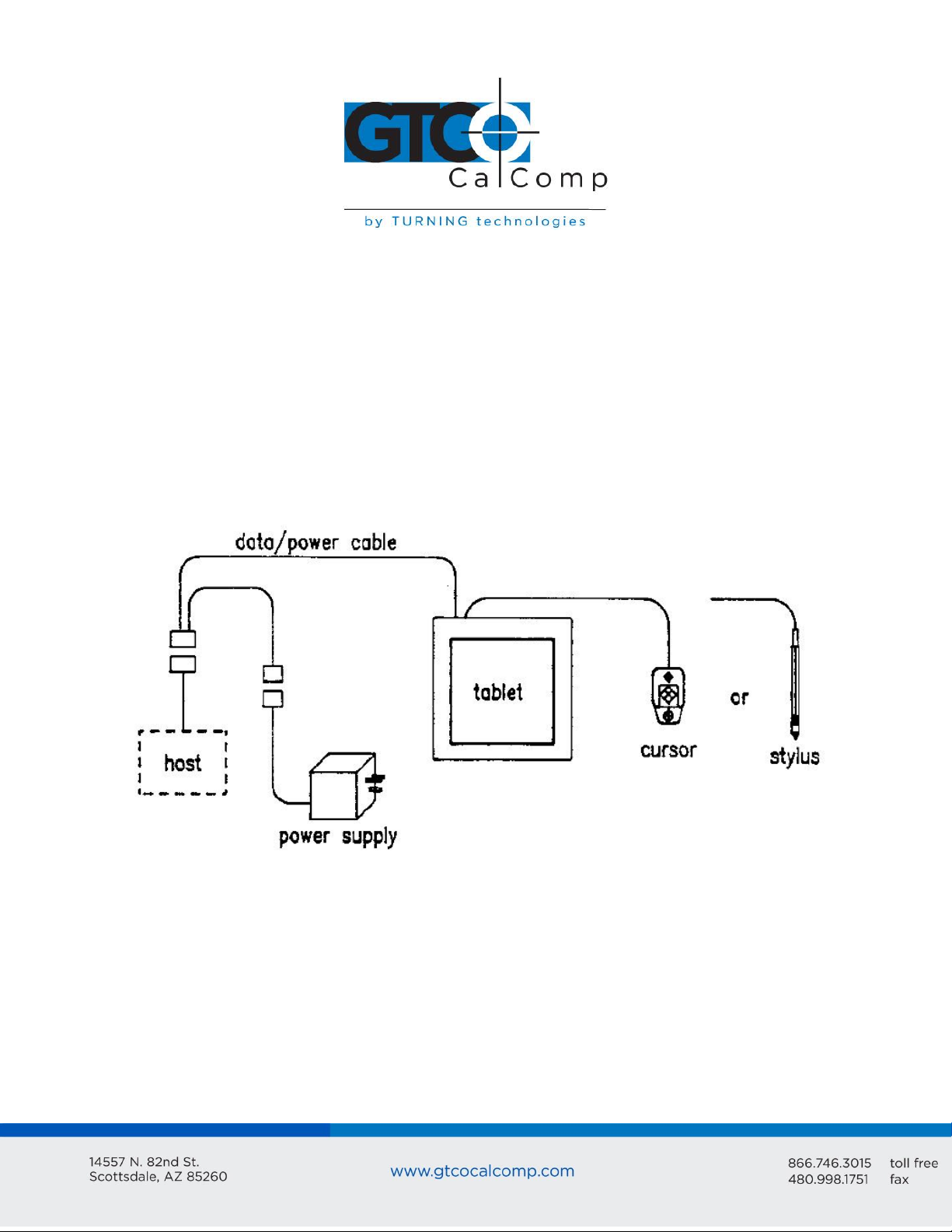
The parts of a standard Bit Pad Two are the tablet, cursor or stylus, data/power cable and
power supply.
Tablet: Table-like surface. The tablet can tilt or lie flat.
Cursor: Handheld device that’s used with the tablet to locate points. A cursor has a
crosshair for precisely sighting the points. They are available with three or four buttons.
Stylus: Pen-like, handheld device. Use it with the tablet to locate points. The stylus has
two buttons; one on the outside of the barrel and another inside the barrel, activated by
pressing the refill tip. Refills are available in marking and non-marking,
Data/Power Cable: Cable and connector assembly that interfaces the data tablet to the
host and power supply.
Page 4
Bit Pad Two 4
Power Supply: Source of power for the Bit Pad Two. It attaches to the data/power cable
and the power line.
Adapter Cables: Cable assemblies that can change the gender of the data/power cable
connector; reverse the communication lines or convert the power supply plug to the
international standards.
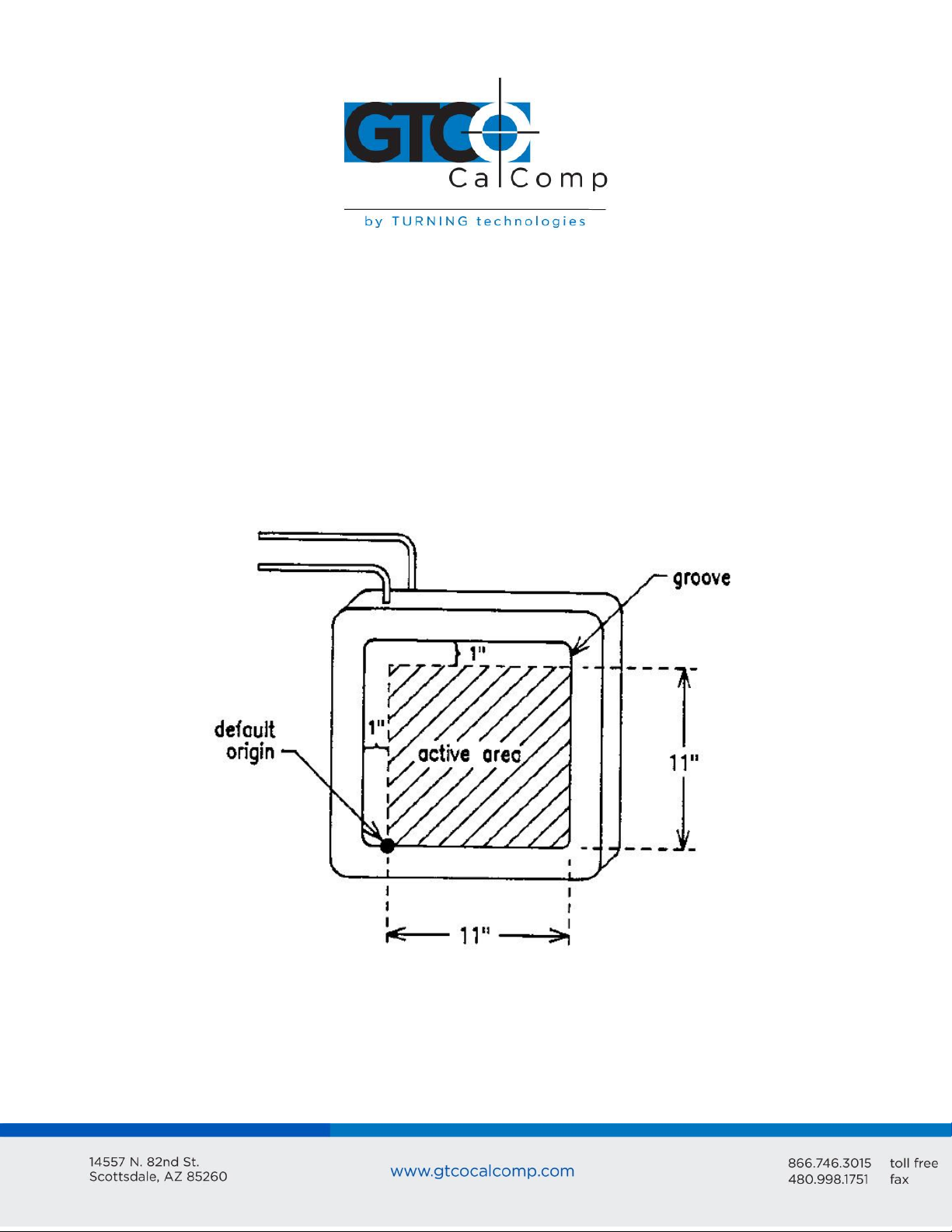
The Bit Pad Two translates the position of the stylus or cursor on the tablet into digital
information and communicates it to the host. The host is represented by a computer. The
stylus or cursor position is expressed as an X, Y coordinate pair. One coordinate pair is
called a report. Reports can only be collected when the stylus or cursor is in the tablet’s
active area and is in proximity.
Proximity is the maximum distance above the active area that the cursor or stylus can be
held and report a valid position. This, in effect, establishes a three-dimensional volume,
within which the cursor or stylus can issue valid reports. Reports issued from outside of
this volume are out of proximity (out-of-prox) and therefore, do not represent the current
position of the stylus or cursor.
Page 5
Bit Pad Two 5
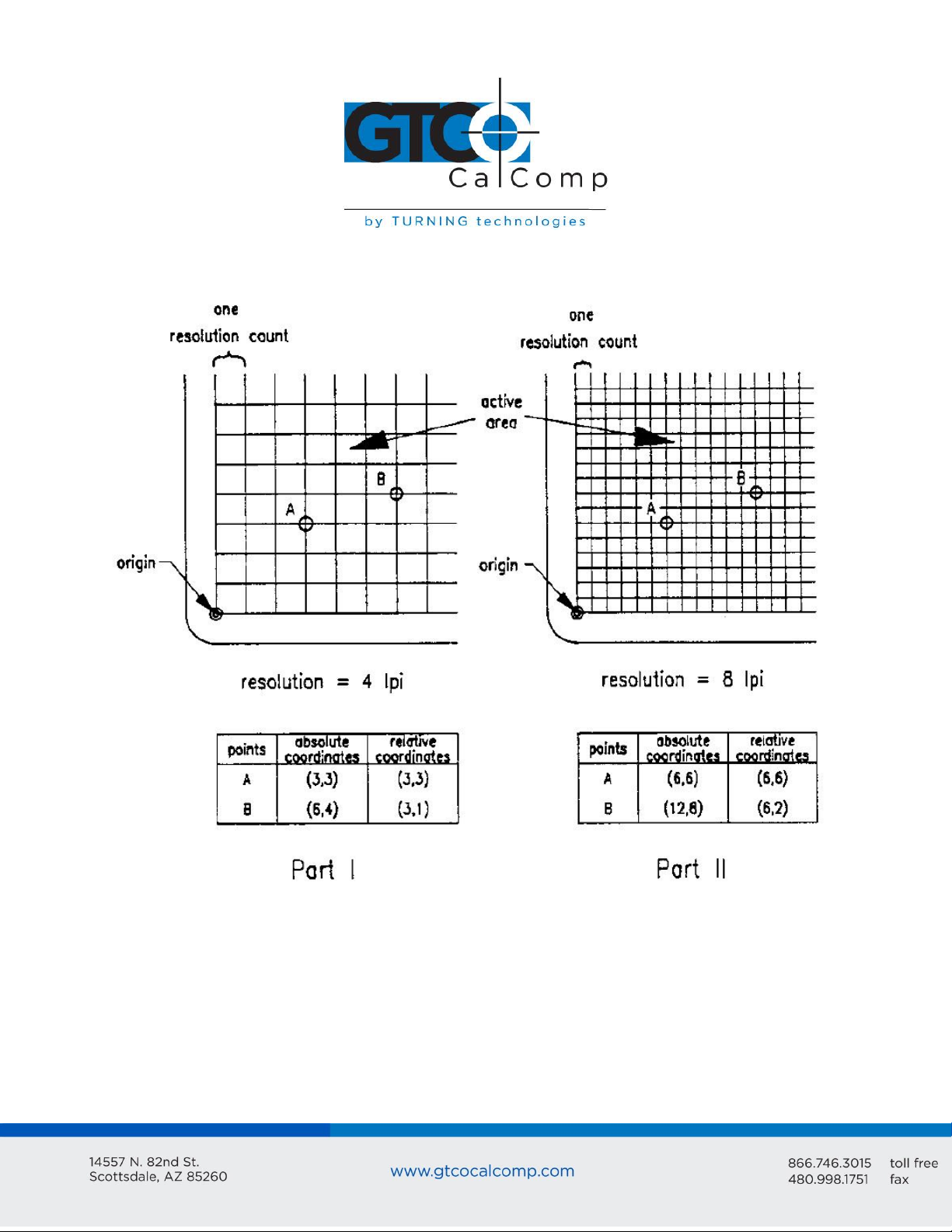
Reports are in counts of resolution, expressed as absolute coordinates or relative
coordinates.
Resolution: Smallest distance or movement that the data tablet can distinguish.
Resolution is a measure of precision and is expressed in lines per inch (lpi) or lines per
millimeter (lpmm).
Counts of Resolution: Unit of measure: one count is the distance between two lines of
resolution.
Absolute coordinates are measured from the tablet’s origin (0, 0). Relative coordinates are
measured relative to the last report location. Reports are in absolute coordinates when the
Page 6

Bit Pad Two 6
data tablet is in Absolute Mode. Reports are in relative coordinates when the data tablet is
in Relative Mode.
Absolute and Relative modes are two of the Bit Pad Two’s many operating characteristics.
Other operating characteristics govern when reports are issued; how fast they are issued
and the tablet resolution.
The operating characteristics can be set by commands from the host or by switches. The
switches, slide or rocker, are grouped in banks of eight per DIP switch. The DIP switches
are located on the printed circuit board inside the tablet.
Also, established by switch are the data tablet’s configuration parameters. These
parameters specify the data communications, such as CTS handshaking and baud rate, and
the data format.
Chapter 2: Configuration Parameters
For successful communication between a Bit Pad Two and its host, the hardware interface
and configuration parameters must be compatible. The hardware interface is RS-232C.
The configuration parameters are:
Proximity transmission
Remote control
Baud rate
CTS handshaking
Report format and cursor output codes
This chapter describes the alternatives available for each of the configuration parameters.
The parameters are switch-selective. Appendix D Quick Reference Sheet of Commands and
Switch Settings summarize the switch settings and defaults that the factory normally uses.
Section A: Proximity Transmission
The data tablet can be configured to:
Transmit reports only when the cursor or stylus is in proximity.
Transmit reports regardless of whether the cursor or stylus is in or out of proximity.
If the data tablet is configured the second way, reports issued from out-of-prox will reflect
that state with a special bit or character. Reports in the binary format have a bit assigned
Page 7
Bit Pad Two 7
to report the proximity status. Reports in the ASCII BCD format use the cursor/stylus flag
character to identify an out-of-prox report.
Section B: Remote Control
The data tablet can be configured to accept or reject commands from the host. When the
remote control is enabled, the data tablet is receptive to commands from the host.
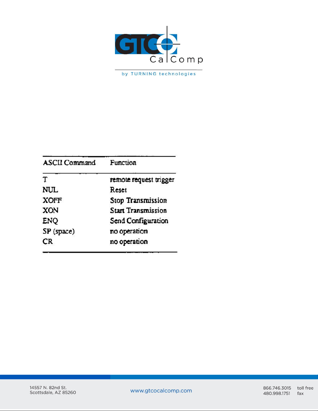
When the remote control is disabled, the data tablet only responds to the following
commands:
Section C: Baud Rate
Baud rate is the number of bits transmitted each second between host and peripheral (Bit
Pad Two) or peripheral and host. The available baud rates are 110, 150, 300, 1200, 2400,
4800, 9600 and 19200.
Section D: CTS Handshaking
The Bit Pad Two supports CTS (Clear to Send) handshaking, hardware governed method of
communications control. The Bit Pad Two is configured as a DTE (Data Terminal
Equipment). Therefore, RTS (Request to Send) and DTR (Data Terminal Ready) are always
asserted.
Page 8
Bit Pad Two 8
If the switch is set to enable CTS handshaking, the data tablet awaits CTS from the host
before it can issue reports. If CTS is not asserted, the data tablet is inhibited from sending
reports. If the switch is set to disable CTS handshaking, the data tablet ignores the CTS line.
Section E: Hardware Interface
The Bit Pad Two has an RS-232C interface. It is full duplex, asynchronous and serial. View
the sections below for the pin assignments and signal levels.
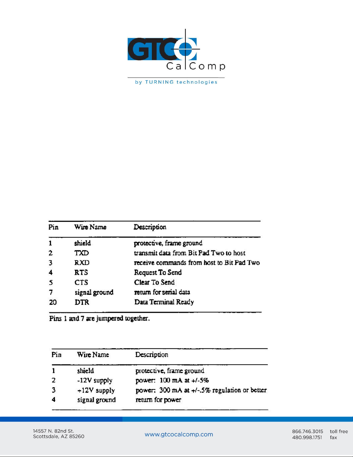
Connector Pin Assignments
The data/power cable is a single, shielded cable terminated with a 25-pin female D
connector and a 4-pin male in-line connector. The D connector plugs into the host and the
in-line connector attaches into the power supply. The pin assignments appear below:
RS-232C Data/Power Cable – Pin Assignments for the 25-Pin D Connector
RS-232C Data/Power Cable – Pin Assignments for the 4-Pin In-Line Connector
Page 9
Bit Pad Two 9
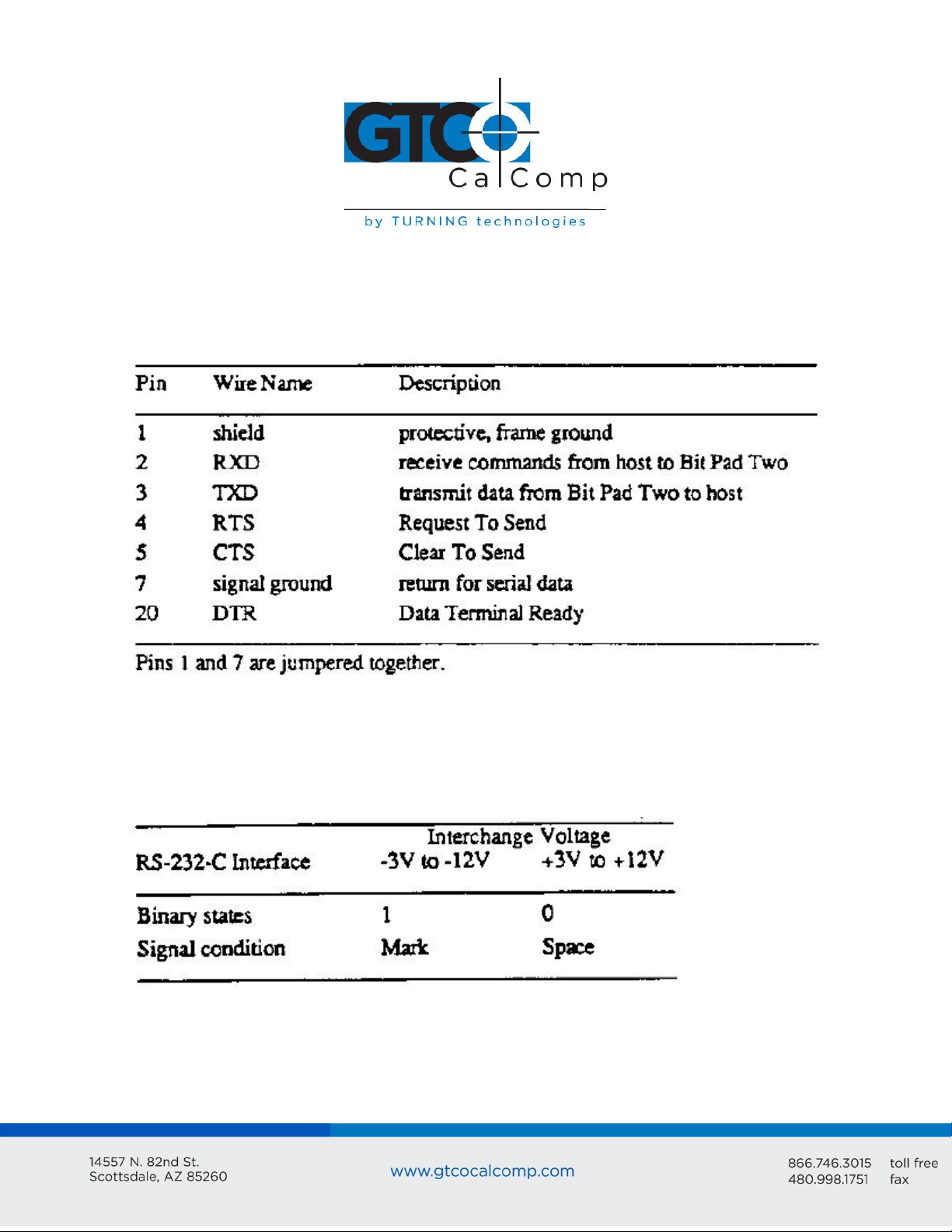
An adapter cable is available to change the connector gender from female to male. Also, a
reversing cable is available to reverse the communications lines; its pin assignments
appear below:
RS-232C Reversing Cable – Pin Assignments for the 25-Pin D Connector
Signal Levels
The table below specifies the signal levels for data transmissions:
RS-232C Signal Levels
The source of the above tablet is the EIA Standard RS-232C: Interface Between Data
Terminal Equipment and Data Communication Equipment Employing Serial Binary Data
Interchange by the Engineering Department of the Electronic Industries Association
(Washington, D.C.: EIA, 1969).
Page 10
Bit Pad Two 10
Section F: Report Format and Cursor Output Codes
Two report formats are available: packed binary and ASCII BCD.
NOTE: To users of other Summagraphics data tablets or digitizers: the formats described
here are specific to the Bit Pad Two and Bit Pad One. Other Summagraphics products have
similarly named formats, but their content may be different. Regardless of format, reports
are in counts of resolution, not in inches or millimeters.
Within the report format:
You can opt to have parity enabled or not.
If parity is enabled, it can be even or odd.
Select the number of stop bits to be one or two.
You have two cursor output codes to choose from.
The Bit Pad Two is normally configured at the factory in the ASCII BCD report format with
parity enabled (set for even parity), two stop bits and cursor output.
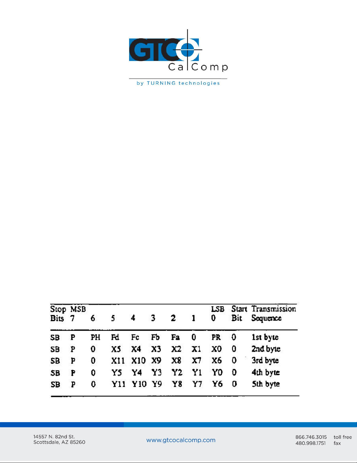
Bit Pad Two Packed Binary Format
The packed binary formats are different for reports issued when the data tablet is in
Absolute Mode vs. Relative Mode. Absolute Mode has 12 bits per coordinate while Relative
Mode has 11 bits and one sign bit per coordinate.
Bit Pad Two Packed Binary Report Format
Page 11
Bit Pad Two 11
LSB
MSB
PR
F
Least significant bit
Most significant bit
Proximity, 0 when in proximity and 1 when out-of-prox
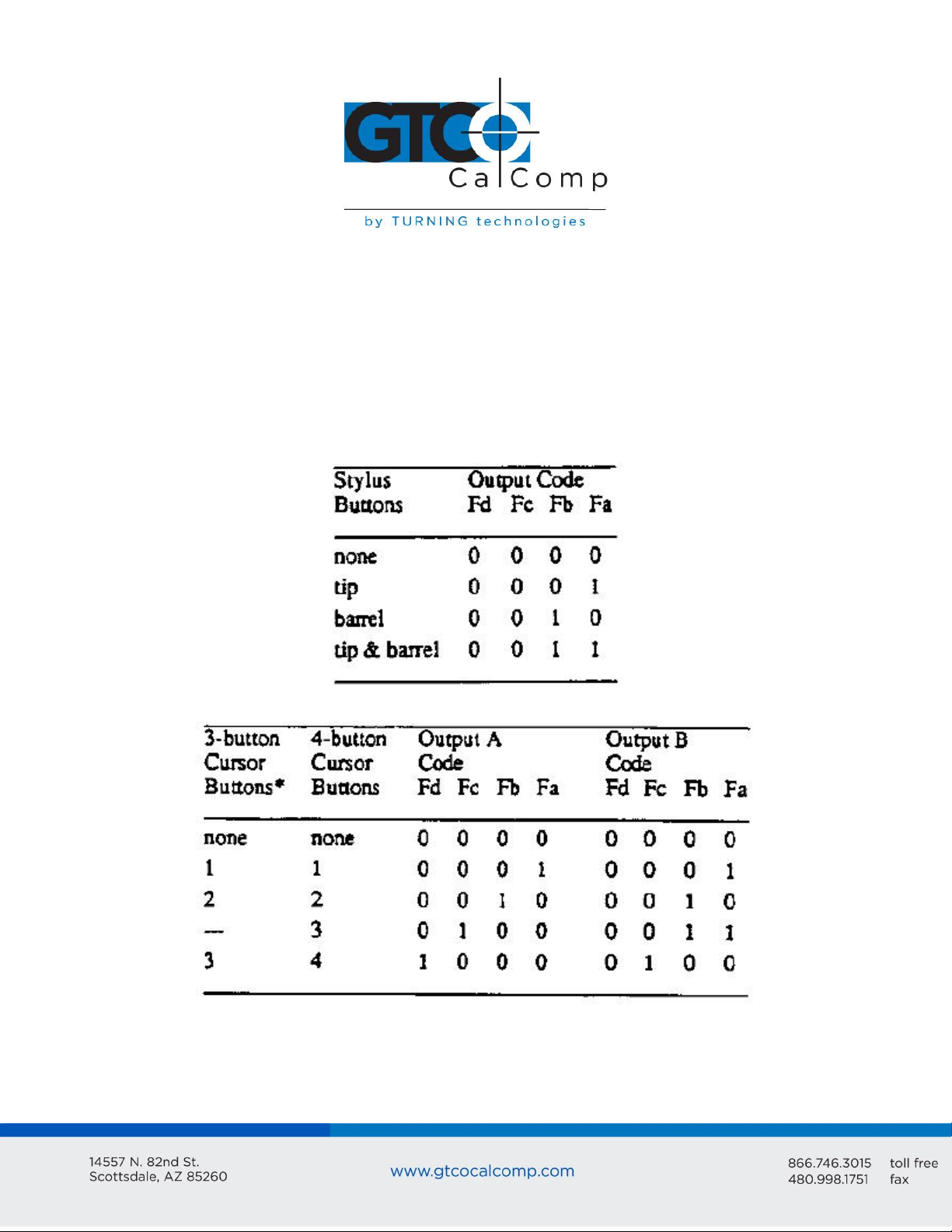
Flag bit, identifying the stylus or cursor buttons being pressed. The cursor
output codes are switch selective:
*On the 3-button cursor, the buttons are distinguished by raised dimples, rather than by
numbered labels. In the table above, 1 corresponds to one dimple; 2 to two dimples, etc.
Page 12

Bit Pad Two 12
PH
P
SB
X0 to X11
and
Y0 to Y11
Phasing bit, which is always 1
Parity bit
One or two stop bits
X and Y coordinate bits.
S
X
,
Y
F
Coordinate sign, in Relative Mode only. For a positive coordinate, the character can be
0 through 9. For a negative coordinate, the character is a minus sign (-).
A digit of the X coordinate; each digit is an ASCII character, 0 through 9.
The delineator character, an ASCII comma.
A digit of the Y coordinate; each digit is an ASCII character, 0 through 9.
Flag character identifying the stylus or cursor buttons being pressed. The cursor output
codes are switch-selective:
NOTE: In Relative Mode, X11 and Y11 are the sign bits. The bit is 0 for a positive coordinate
and 1 for a negative coordinate. Furthermore, the remaining bits for a negative coordinate
are in the two’s complement form.
Bit Pad Two ASCII BCD Format
When the data tablet is in Absolute Mode, the ASCII BCD report format is:
XXXX,YYYY, F<CR> or XXXX,YYYY,F<CR><LF>
When the data tablet is in Relative Mode, the ASCII BCD report format is:
SXXX,SYYY,F<CR> or SXXX,SYYYY,F<CR><LF>
As shown in the above formats, the terminator can be a carriage return (<CR>) or a carriage
return and a line feed (<LF>). This is switch-selective.
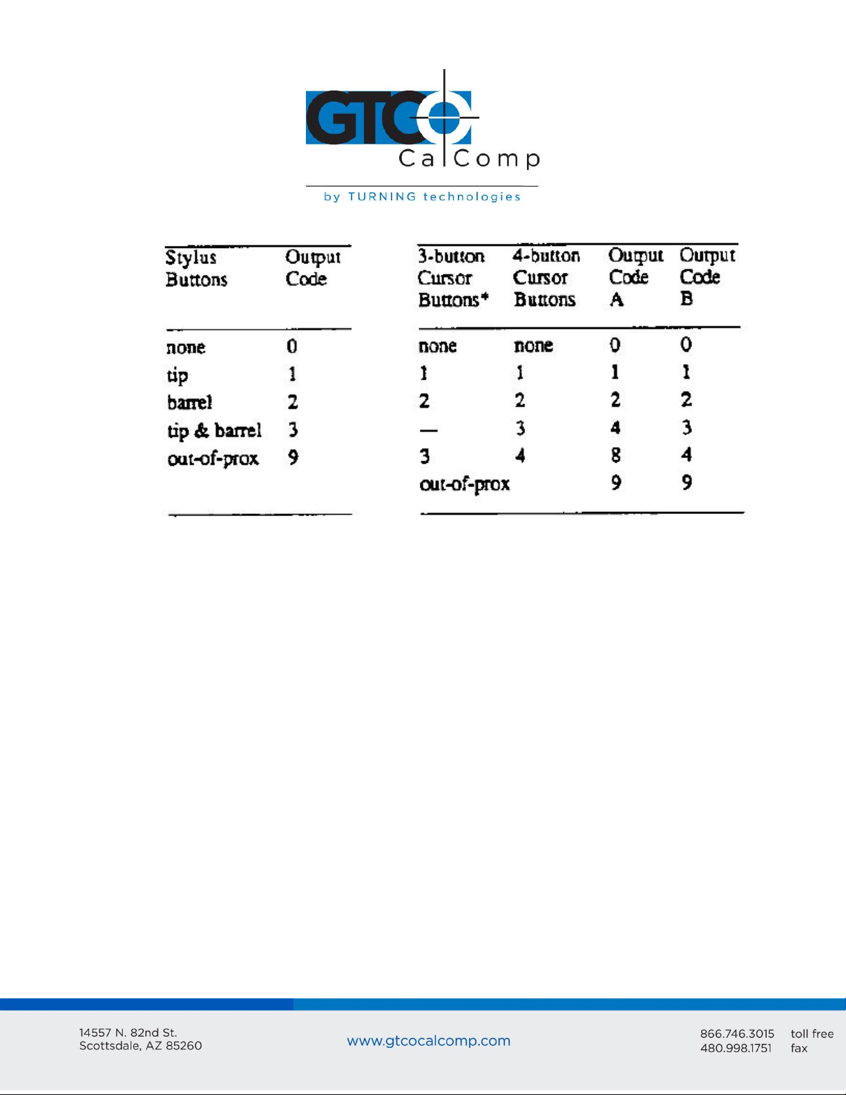
NOTE: The character 9 is in the cursor/stylus flag position when a report is issued from outof-prox.
Key:
Page 13
Bit Pad Two 13
*On the 3-button cursor, the buttons are distinguished by raised dimples, rather than
by numbered labels. In the table above, 1 corresponds to one dimple, 2 to two dimples
and etc.
<CR>
<LF>
ASCII carriage return
ASCII line feed
Chapter 3: Guidelines for Writing a Software Driver
A computer must have a driver in order for the Bit Pad Two to be connected. The driver is
a software subroutine that collets and decodes Bit Pad Two reports for use by another
(master) program. This section provides some guidelines, in the form of flowcharts, for
writing a driver.
The flowcharts are for a Bit Pad Two using the packed binary report format. The steps are
general for any set of operating characteristics.
NOTE: In the context of these charts, normalize means to combine the two coordinate
bytes into the format required by your master program.
Page 14
Bit Pad Two 14
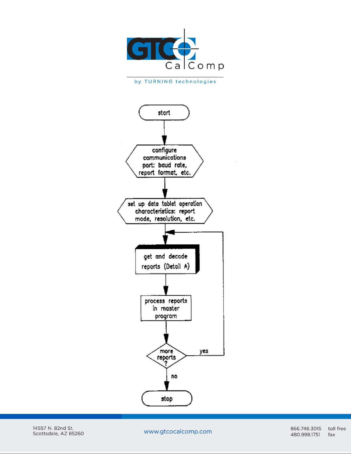
General Flowchart for Master Program to Read and Process Data Tablet Reports
Page 15
Bit Pad Two 15
Detail A: Get and Decode Reports Subroutine
Page 16

Bit Pad Two 16
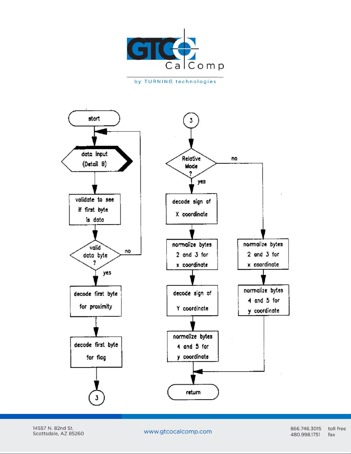
Detail B: Data Input Subroutine
Page 17

Bit Pad Two 17
Chapter 4: Operating Characteristics and Commands
Bit Pad Two has a variety of operating characteristics and functions. The operating
characteristics control the report flow, report content and tablet resolution.
Set the Bit Pad Two’s operating characteristics or initiate the functions with commands
from the host or with the switches inside the tablet. The table below identifies the selector
methods available:
Methods of Operating Characteristic and Function Control
Commands override switch settings.
NOTE: The operating characteristics revert to the switch settings, however, each time you
power up the data tablet or issue the Reset command.
Page 18

Bit Pad Two 18
Each characteristic or function and its commands are defined. For easy reference, the
commands appear in ASCII and hexadecimal. Appendix B ASCII Conversion Chart also
provides the binary, decimal and octal conversions. A summary of the commands and
switch settings appears in Appendix D Quick Reference Sheet.
The command byte format uses the same conventions as those used in the report formats:
one start bit, seven data bits, an optional parity bit and one or two stop bits.
Commands are one byte long. The Bit Pad Two command buffer can hold ten bytes;
therefore, up to ten bytes can be sent to the Bit Pad Two in quick succession.
Section A: Controlling the Report Flow and Content
Use the operating characteristics described in the section to control when reports are
issued, how fast they are issued and coordinate content. Furthermore, reports can be
gated (allowed to flow or not) with the Start and Stop Transmission commands.
Some characteristics are called modifiers because they can be combined with primary
modes. The primary modes are Stream, Switch Stream, Point and Remote Request modes.
The modifiers are Absolute, Relative and Increment modes, as well as Report Rate.
Primary Modes: Stream, Switch Stream Modes and Report Rate
Command
Page 19

Bit Pad Two 19
Switch Setting:
Stream Mode:
Switch Stream Mode:
Report Rate: DIP #1
Please note that one command sets both the mode and Report Rate. However, five
switches must be set to accomplish the same setting, two for the mode and three for the
Report Rate.
Stream Mode
Bit Pad Two continuously issues reports. It is not necessary to press a cursor or stylus
button.
NOTE: To eliminate redundant reports from being issued when the cursor or stylus is
stationary, use Stream Mode together with Increment Mode.
Switch Stream Mode
Bit Pad Two continuously issues reports when a cursor or stylus button is pressed.
Page 20

Bit Pad Two 20
Report Rate
The Report Rate is the number of reports the data tablet issues each second. Use it with
Stream or Switch Stream modes. Note that the Report Rate settings, such as 2 rps or 70
rps, are approximations. The rate at which the data tablet actually sends reports depends
on the baud rate and the report format. The following tables identify the rates you can
expect.
Report Rates Relative to Baud Rates for Reports in Binary Format
Report Rates Relative to Baud Rates for Reports in ASCII BCD Format
The Report Rates at 110, 150 and 300 baud are slower.
Page 21

Bit Pad Two 21
Command:
Switch Setting:
Command:
Switch Setting:
Command:
Switch Setting:
Point Mode
In Point Mode, the Bit Pad Two issues one report each time a cursor or stylus button is
pressed. Reports can be issued up to the maximum Report Rate available for the set baud
rate.
Remote Request Mode
In Remote Request Mode, the Bit Pad Two issues one report each time the host sends a
trigger command. Issue the mode command once. Thereafter, send only a trigger
command for each report.
After Remote Request Mode is initiated, the Bit Pad Two takes between two and ten
milliseconds to issue the report resulting from the first trigger command. Subsequent
reports can be issued up to the maximum Report Rate available for the set baud rate.
Modifiers
Absolute Mode
Page 22

Bit Pad Two 22
Command:
Switch Setting:
In Absolute Mode, the Bit Pad Two issues reports as absolute coordinates. Absolute
coordinates are measured relative to the tablet origin. Reports issued from out-of-prox are
repeats of the last valid coordinate pair.
NOTE: When reports are in binary format and the data tablet is in Absolute Mode, the
maximum reportable value is 4095. (Reports in ASCII BCD format have no restrictions.)
Reports larger than this are detailed as the maximum value (4095). This, in effect, restricts
the resolution setting to 254 lpi if you want the entire Bit Pad Two active area (11” x 11”)
available for digitizing. Higher resolutions can be used; however, the active area shrinks
accordingly. The following table specifies the maximum length of each active area’s axis
from the tablet origin for resolutions higher than 254 lpi:
Relative Mode
In Relative Mode, the Bit Pad Two issues reports as relative coordinates. Relative
coordinates are measured relative to the last issued report, not the tablet origin.
In Relative Mode, reports can have positive or negative values. Reports issued while the
cursor or stylus is out-of-prox are zero.
NOTE: When the data tablet is in Relative Mode, the maximum negative coordinate that
can be reported is restricted. In the binary format, the maximum reportable value is 2047.
In the ASCII BCD format, the maximum reportable value is 999. Reports larger than these
values are detailed as the maximum value. (Positive coordinates are not restricted.)
Page 23

Bit Pad Two 23
Command:
Switch Setting:
The effect is a restriction of the maximum delta between reported points. The delta is the
distance from the last report to the current one. The maximum delta varies, depending on
the tablet’s resolution setting. This relationship is quantified in the table below:
Increment Mode
In Increment Mode, the Bit Pad Two sends a report only when the cursor or stylus has
traveled a minimum distance in the X or Y direction. This minimum distance is the
increment. The increment is defined by you and applies to both axes. Because redundant
reports are not sent to the host, Increment Mode is useful in reducing data output.
Page 24

Bit Pad Two 24
Point
Report
Description
1
2
3
(0,0)
(10,5)
(20,13)
Only X is satisfied. The actual value of Y is transmitted.
No point is transmitted between points 2 and 3 because the cursor
or stylus did not move ten resolution counts in either the X or Y
directions.
The increment is satisfied from the last point along the X axis only;
the Bit Pad Two issues the new report.
Here’s a description of how Increment Mode works: last report issued becomes the center
of an imaginary square whose sides are twice the increment value. The cursor can move
anywhere inside the imaginary square without a report being issued. As soon as the
increment is satisfied along either axis, the Bit Pad Two transmits the actual X and Y
coordinates of the point. The new point becomes the center of a new, imaginary square.
Example: Part A shows the imaginary square created around each report point; the
increment is five. Part B shows the reports issued as the cursor or stylus travels across the
tablet; the increment is 10.
The five points issued in Part B are numbered in order.
Page 25

Bit Pad Two 25
4
5
(30,7)
(32,17)
The increment is satisfied from the last point along the X axis only;
the Bit Pad Two issues the new report.
The increment is satisfied from the last point along the Y axis only;
the Bit Pad Two issues the new report.
Section B: Combining Characteristics
This section describes some of the nuances of combining primary modes and modifiers.
Reports are not issued in response to buttons being pressed when the data tablet is
in Remote Request Mode.
Reports are issued in response to either buttons being pressed or remote requests
when the data tablet is in Point, Stream or Switch Stream Mode.
When the data tablet is in Stream, Switch Stream or Point Mode together with
Increment Mode and a button is pressed, the last coordinate pair that satisfies the
increment is reported.
When the data tablet is in Stream Mode and Increment Mode or Switch Stream
Mode and Increment Mode, reports are issued as follows:
o A report cannot be issued until the increment has been satisfied.
o If the increment has been exceeded and the Report Rate mandates that a
report be issued, the last coordinate pair that satisfies the increment is
reported.
When the data tablet is in Point and Increment modes, reports are issued as follows:
o If a button is pressed, but the increment has not been met, the last
coordinate pair that satisfies the increment is reported.
o If the increment has been exceeded and a button is pressed, the actual stylus
or cursor position is reported.
Page 26

Bit Pad Two 26
Command:
Switch Setting:
When the data tablet is in Remote Request and Increment modes, regardless of
whether the increment has been satisfied or not, the actual position where the
stylus or cursor is when the data tablet receives the remote trigger is reported
position.
If Point or Remote Request modes are set by switch rather than by command, the
Report Rate, also set by switch, is valid. Consequently, the Report Rate has priority
over buttons or remote triggers.
Section C: Other Commands
Resolution
Resolution is the smallest distance or movement that the data tablet can distinguish. It’s a
measure of precision and is expressed in lines per inch (lpi) or lines per millimeter (lpmm).
NOTE: The data format and coordinate mode both play a role in which resolutions are valid
for the entire tablet.
Page 27

Bit Pad Two 27
Command:
Switch Setting:
Command:
Switch Setting:
Send Configuration
Use the Send Configuration command to send a report to the host that identifies the data
tablet model and its version of software. The output looks like this:
MM1103_BIT_PAD_II_by_Summagraphics_Version_n.n<CR><LF>
The underlines are spaces; n.n is the version number and the line feed is switch-selective.
Transmission Control
The Start Transmission and Stop Transmission commands act as gates, allowing reports to
be sent or not sent from the Bit Pad Two to the host. These commands control data flow,
regardless of the report mode. (Stop Transmission and Start Transmission are equivalents
of the transmission protocols XOFF and XON.)
Stop Transmission places the data tablet on standby. It is useful for systems that do not
constantly use the data tablet. End the standby state by sending the Start Transmission
command.
If a report is interrupted by Stop Transmission, no data is lost. The report is severed at the
end of the byte. When the Start Transmission command is issued, the next byte in that
report is sent, intact. To avoid corrupted data, the host software should not look for a
phasing bit at the beginning of resumed transmission.
Page 28

Bit Pad Two 28
Command:
Switch Setting:
Report Mode = Stream
Coordinate System = Absolute
Report Rate = 100 rps
Increment = 0
Resolution = 200 lpi
Command:
Switch Setting:
The data tablet will respond to other commands, such as a command to change the
resolution, while it is on standby. If the Reset command is issued while the data tablet is on
standby, the data tablet honors the Reset command, but does not retract the XOFF state.
Reset
Use the Reset command to return the operating characteristics to their current switch
settings.
The factory-set defaults are:
After a Reset is issued, there is a 10 millisecond delay before the Bit Pad Two is ready to
receive information from the host.
NOP (No Operation)
The data tablet performs no operation (NOP) when one of these commands is issued to it.
This function can be used as a pad between command sequences, e.g. between XON and
XOFF.
Page 29

Bit Pad Two 29
Chapter 5: Checking the Data Tablet
A convenient functional check of the data tablet can be performed by connecting Bit Pad
Two to a terminal and moving the cursor or stylus across the tablet’s active area. (The
output is easier to interpret if you have the report format set for ASCII BCD.) The X and Y
values should increase as the cursor or stylus slides from the tablet origin toward the end
of the axis. This is depicted in the following illustration:
Another mechanism for checking a Bit Pad Two is the Self-Test diagnostic function.
Page 30

Bit Pad Two 30
Command:
Switch Setting:
Section A: Self-Test Diagnostic Function
Use the Self-Test command to perform tests on the tablet and cursor or stylus. Self-Test
checks:
Analog circuitry
Cursor or stylus connection, operation and location
Digital circuitry
After the test is performed, the results are sent to the host. The results are transmitted in
one byte in the following format:
Page 31

Bit Pad Two 31
+45 degrees to +110 degrees Fahrenheit
+7 degrees to +43 degrees Celsius
8% to 80% relative humidity, non-condensing
-45 degrees to +145 degrees Fahrenheit
-43 degrees to +63 degrees Celsius
8% to 80% relative humidity, non-condensing
If the Self-Test output byte is an ASCII O or G, the data tablet passed the diagnostic tests.
(An O simply indicates that the stylus/cursor is in proximity. A G indicates that it is out-of-
prox.)
Section B: In Case of Failure
If the Bit Pad Two does not operate or fails the Self-Test, follow these steps:
1. Power down the Bit Pad Two.
2. Check that cables are firmly attached.
3. Ensure that the host is working properly.
4. If possible, issue each diagnostic command and review the results.
Chapter 6: Operating Environment, Installation, Care and Service
Section A: Operating Environment
Temperature and Humidity
Operate Bit Pad Two within these temperature and humidity ranges:
Acceptable non-operating conditions are:
Extremes in environment can cause degradation of operation.
Page 32

Bit Pad Two 32
Power
The power supply shipped with Bit Pad Two provides the proper power: 300mA at +12VDC
with +/-.5% regulation or better and 100 mA at -12VDC with +/-5% regulation or better.
Section B: Unpacking and Installation
Unpacking
Immediately upon receipt, inspect the package for damage. If damage exists:
1. Open the package and inspect the damage.
2. Report the damage to the carrier as soon as possible, preferably within 72 hours or
receipt.
3. Record the damaged items on the freight bill.
4. Write to the carrier: state that the shipment was damaged, when it was received and
request an inspection.
5. Keep the shipment in its original container until an inspection is made by the carrier.
6. Notify GTCO CalComp by Turning Technologies at 1.866.746.3015 or email us at
gtco.support@gtcocalcomp.com.
Otherwise, unpack the Bit Pad Two. The package should include:
Tablet with data/power cable attached
Four rubber feet
Bit Pad Two Data Tablet Technical Reference
Power supply
Purchasable options include:
Cursor/Stylus
Gender changer or reversing cable
Power cable (for international power supply)
Page 33

Bit Pad Two 33
Installation
A brief summary of the steps for assembling and installing a Bit Pad Two is as follows:
1. Configure Bit Pad Two data tablet.
2. Adjust the tilt or use flat
3. Attach stylus holder, if applicable.
4. Connect the stylus or cursor to the tablet.
5. Attach the tablet to the host.
6. Connect the tablet to the power source.
Page 34

Bit Pad Two 34
Page 35

Bit Pad Two 35
1. Configure Bit Pad Two Data Tablet
The Bit Pad Two’s configuration parameters are set at the factory to your
specifications. If however, you want to adjust the configuration, you can do so by
setting the switches inside the tablet. It is advantageous to do this step before
connecting the unit with the host since it requires disassembling the tablet.
NOTE: Every time you open the tablet cabinetry, observe the following instructions:
Discount the tablet from its power source before opening the case. Special care must be
taken when the tablet case is open. Components on the printed circuit board, especially
the microprocessor, can be damaged or destroyed by electrostatic discharges. This can be
avoided by preventing static electricity from building up.
Have an antistatic floor covering under you and the tablet.
Use a conductive, grounded work surface.
Keep yourself at ground potential with conductive wrist bands and a 1 megohm
resistor to ground.
Do not wear clothes or shoes made of materials that promote static electricity, e.g.
nylon, polyester or wool.
To access the board, lay the tablet upside down on a table. Remove the Phillip head screws
along the outer edge. Gently remove the tablet back.
The switches are slide or rocker switches, grouped in banks of eight switches per DIP
switch. The DIP switches are labeled SW1, SW2, and SW3 and are located along the
periphery of the printed circuit board.
Page 36

Bit Pad Two 36
The ON and OFF positions are labeled on each switch. Set a slide switch by sliding it to the
desired position. Set a rocker switch by pressing down on the side next to the desired
position. Use a pointed instrument. Do NOT, however, use a pencil or another instrument
that could deposit residue, e.g. graphite or ink, on the switch. This could cause the switch
to malfunction.
2. Adjust the Tilt or Use Flat
Bit Pad Two can tilt or lie flat. The tilt mounting is already attached to the back of
the tablet when shipped. It tilts four to six degrees or ten to 14 degrees, depending
on the position of the extenders.
For the tablet to lie flat, the tilt mounting must be removed and the four rubber feet
attached to the tablet bottom:
Slide the tilt mounting toward the edge of the tablet where the data/power
cable protrudes.
Page 37

Bit Pad Two 37
Lift the tilt mounting gently to clear the cursor/stylus socket. Remove the tilt
assembly.
Remove the paper backing from the rubber feet. Stick the feet on the tablet
back, approximately one inch from each corner.
3. Attach Stylus Holder (if applicable)
Attach the stylus holder anywhere along the tablet edge within five inches from the
tablet top. Refer to the illustration below:
Remove the protective paper from the adhesive tape. Attach the taped side to the
back of the tablet.
4. Connect the Stylus or Cursor to the Tablet
The stylus or cursor plugs into a phone jack on the underside of the tablet. Cursors
and stylus are interchangeable. Upon changing from a stylus to a cursor or from a
cursor to a stylus, reset the tablet by powering it down or by issuing the Reset
command.
NOTE: When the tablet is powered and the stylus is plugged in, but not in use, store the
stylus in the stylus holder. This allows air to freely circulate around the tip. Not providing
air circulation could damage the stylus from overheating.
Page 38

Bit Pad Two 38
5. Connect the Tablet to the Host
The RS-232C cable is equipped with a 25-pin female D connector with a jack screw.
The host must have a 25-pin male D connector (AMP P/N 205208-1). To lock the
connectors together, the host connector must have a screw lock (AMP P/N 205817-
1).
If the system requires them, adapter cables are available to change the connector
gender from female to male; or to reverse communication lines. Install an adapter
cable between Bit Pad Two data/power cable and the host.
6. Connect the Tablet to the Power Source
Plug the four-pin connector of the pigtail cable into the power supply. In turn, plug
the power supply into the wall outlet. For international power supplies, a plug
adapter cable must be connected between the power supply and the wall outlet.
Changing the Stylus Refill
As depicted in the illustration below, to change the stylus refill, pull the cap straight out;
likewise, the refill. Replace the refill and cap.
NOTE: Do not remove the metal guide-ring in the cap. It keeps the refill in place.
Page 39

Bit Pad Two 39
GTCO CalComp by Turning Technologies
14557 N. 82nd Street
Scottsdale, AZ 85260
Toll Free: 866.746.3015
Fax: 480.998.1751
Section C: FCC Considerations
As stated by FCC rules and regulations, Bit Pad Two must be installed and operated in
accordance with the procedures appearing in this manual. In addition, to ensure that EMI
shielding requirements are met, the host’s interface cabling connector must have a metal
shroud, grounded to the host chassis.
Section D: Care and Cleaning
Avoid sharply banging or dropping the tablet, cursor or stylus.
Never immerse any part in fluid.
Disconnect the tablet from its power source before cleaning it.
The Bit Pad Two tablet surface is made of plastic. To clean, use only a cotton flannel cloth
with mild detergent and water. Never use a hydrocarbon cleaner such as acetone or an
abrasive cloth. These mar the tablet finish.
Section E: Service
For technical support and service, contact your local GTCO CalComp by Turning
Technologies representative or GTCO CalComp by Turning Technologies at:
If you return a Bit Pad Two for repair, a Return Authorization Number must be on the
outside of the package and on all accompanying paperwork. Obtain a Return Authorization
Number from GTCO CalComp by Turning Technologies Customer Support. When
contacting Customer Support, please have ready the tablet serial number purchase order
number.
NOTE: Do not ship any equipment to GTCO CalComp by Turning Technologies without a
Return Authorization Number.
Page 40

Bit Pad Two 40
Overall Dimensions
Active Area (nominal)
Weight
16.0” x 16.2” x 0.80”
406mm x 412mm x 20mm
11” x 11”
280mm x 280mm
Maximum: 7 pounds
3.2kg
U.S.A.
102V to 132V; 58Hz to 62Hz; NEMA 5-15P plug
International
197V to 264V; 48Hz to 52Hz; I.E.C. Universal power receptacle
Japan
90V to 110V; 42Hz to 62Hz; NEMA 1-15P plug
Color: Pearl white
Finish: Matte (silk-like)
Material: Cycolac KJW flame-retardant ABS plastic
Appendix A: Specifications
Physical Description
Power Requirements
300 mA at +12VDC with +/-.5% regulation or better and 100 mA at -12VDC with +/-5%
regulation or better.
Optional Power Supplies
Material and Cosmetics
Operating Specifications
A Bit Pad Two performs to the specifications listed below. The word typical is used to
describe accuracy and proximity. Typical means the unit performs to that specification of
more than 90% of the active area at 25 degrees Celsius. A slight degradation occurs at the
extreme edges and corners of the active area.
The following specifications are provided to aid in the understanding and use of the
product.
Page 41

Bit Pad Two 41
Accuracy
The similarity of a distance measured by the tablet with the actual distance.
Cursor Eccentricity
How much the electrical center varies from the crosshair center as the cursor is rotated
through 360 degrees.
Jitter
Repeatability error of short duration caused by electrical noise.
Proximity
Greatest distance above the drawing area that the pointing tool can be raised and still be
sensed by the tablet.
Repeatability
How closely you receive the same coordinates from the repeatedly locating the point.
Repeatability takes temperature range and jitter into consideration.
Page 42

Bit Pad Two 42
Appendix B: ASCII Conversion Chart
Page 43

Bit Pad Two 43
Page 44

Bit Pad Two 44
Page 45

Bit Pad Two 45
Appendix C: How the Bit Pad Two is Different from Bit Pad One
Bit Pad Two is a second generation data tablet. It is, with some minor exceptions, a plug
replacement for Bit Pad One. As an improved version of its predecessor, dissimilarities do
exist. For example, the Bit Pad Two uses more advanced hardware and different
technology.
Some noteworthy exceptions regarding Bit Pad Two:
Does not require biasing: pulling a magnet over the tablet.
Report formats, binary and ASCII BCD, include a bit or character identifying whether
the stylus/cursor is in or out of proximity.
Offers more operating characteristics to choose from, such as Relative Mode.
Maximum baud rate is 19.2K.
Hardware interface is RS-232C.
Does not have a Stop Mode, as such. Instead, it offers two alternatives, XOFF and
Remote Mode. Note that the command previously used by Bit Pad One to initiate
Stop Mode is now the command for Remote Request Mode.
Page 46

Bit Pad Two 46
Switch Settings: DIP Switch 1
Page 47

Bit Pad Two 47
Switch Settings: DIP Switch 3
Page 48

Bit Pad Two 48
Corporate Headquarters
14557 N. 82nd Street
Scottsdale, Arizona 85260
Tel: 1-866-746-3015
Support: 1-866-746-3015
Fax: 480-998-1751
Support: 1.866.746.3015
Copyright© 2014 GTCO CalComp by Turning Technologies, Inc.
Bit Pad Two is a trademark of GTCO CalComp by Turning Technologies, Inc.
All other products and company names are the trademarks or registered trademarks of
their respective owners.
The information contained in this document is subject to change without notice. GTCO CalComp by
Turning Technologies assumes no responsibility for technical, or editorial errors, or omissions that may
appear in this document, or for the use of this material. Nor does GTCO CalComp by Turning
Technologies make any commitment to update the information contained in this document. This
document contains proprietary information which is protected by copyright. All rights reserved. No part of
this document can be photocopied or reproduced in any form without the prior, written consent of GTCO
CalComp by Turning Technologies, Inc.
 Loading...