

Page 1

User’s Manual
for electrical and electronic circuits
Page 2

Table of contents.
1 Check out list Page 1
2 Start-up Page 1
3 Turning on and off the FF310T and FF310R Page 1
4 Setting the sensitivity level Page 2
5 How to use the sensor Page 3
6 Locating short circuits Page 3
7 Wire tracing Page 4
8 Locating current leaks Page 4
9 Locating open circuits Page 5
10 Wire identifi cation Page 5
11 Hook up reference chart Page 6
12 General procedures Page 7
13 Special tracing procedures Page 8
14 Technical specifi cations Page 10
15 CT8002AA Professional Circuit Tester Page 10
16 CT6100 Fuse Socket Connectors Page 11
17 Care of the unit Page 11
18 Warranty Page 12
Caution
Very Important: Read this fi rst
•
For use only with DC voltage. Do not connect to circuits exceeding 42 volts DC under
any circumstances.
•
DO NOT USE on AC voltage.
•
Do not use on any circuit directly or indirectly connected to AC lines or any other AC
power source.
•
Do not use with any component or part of the ignition system.
•
Before using this device check the vehicle’s electrical wiring and disconnect any part
or subsystem sensitive to voltage and current pulses such as air bags, electronic
control modules, etc.
•
Always follow the instructions and procedures indicated in the vehicle’s
service manual before attempting to disconnect any part or subsystem of the
electrical circuit.
Exceeding the limits listed above when using this apparatus, or not observing
the precautions listed above can expose you to physical injury and permanently
damage your instrument and parts and components of the vehicle under test.
“V Ready” and “GTC” are registered trademarks of General Technologies Corp.
Page 3

1 - Check out list
The FF310 FaultFinder set consists of:
FF310R - Receiver
FF310T - Transmitter
CT8002AA Professional Circuit Tester
CT6100 Fuse Socket Connectors
2 factory supplied 9 volt alkaline batteries, type Duracell MN1604
Foam padded polypropylene carrying case.
User’s manual.
2 - Start Up
Both the FF310T and FF310R are factory supplied with batteries. To install the batteries
follow the steps below:
1. Open battery drawer at back of each unit (factory supplied batteries
are disconnected).
2. Remove the battery, and connect it observing the polarity of the battery connector,
repeating the operation on both units.
3. Press the On/Off button on the FF310T, green LED will start fl ashing. If green LED
does not starts fl ashing, check the battery polarity and reinstall if necessary . To turn
the unit off, press the On/Off button again.
4. Press the On/Off button on the FF310R, green LED will turn on. If the green LED
does not turn on, check the battery polarity and reinstall if necessary. To turn the
unit off press the On/Off button again.
3 - Turning On and Off the FF310T and FF310R
FF310T
The transmitter is turned on and off by momentarily pressing the On/Off
button, and it must be turned off manually after use by pressing the On/Off button. Before
storing the unit check to make sure that all lights are off, failure to do so will result in a
much shorter battery life.
FF310R
The receiver can be turned on and off manually by momentarily pressing the On/Off button,
however after 3 minutes of not being used, it will turn off automatically to conserve battery
power. Turning the unit off manually will prolong battery life.
Low battery indicator
From time to time the batteries on both units will need to be replaced. When the battery
is below the minimum operating voltage, upon turning the unit on (FF310T and FF310R)
both lights will fl ash for 1 second and the unit will turn off automatically . In this case replace
the batteries with a new set of 9 Volt alkaline batteries. To install the new batteries, follow
the instructions in the preceding section: 2 – Start Up.
Page 1
Page 4

Page 2
4 - Setting the sensitivity level
The FF310R has three user selectable sensitivity ranges: ‘Low’, ‘Medium’ and ‘High’.
These ranges allow the technician to choose the degree of sensitivity most suitable to
the particular detection being performed.
4.1 Checking the current sensitivity setting:
The FF310R’s current sensitivity setting is displayed when the On/Off button is pressed
for 2 or 3 seconds while the unit is ‘ON’ (steady green indicator on). The high sensitivity
setting generates a quick triple fl ashing of the green LED, a double fl ashing in the medium
sensitivity range and a single fl ashing indicates a low sensitivity level setting.
Green LED shows a: FF310R set to:
Single (1) fl ash and beep Low sensitivity
Double (2) fl ash and beep Medium sensitivity
Triple (3) fl ash and beep High sensitivity
When turned off, the FF310R will retain the last selected sensitivity setting.
4.2 Procedure to select the FF310R’s range :
1. Unit should be on, if not, turn it on by momentarily pressing the
On/Off button.
2. Press and hold On/Off button for approximately 3 seconds until a beeping and fl ashing
occurs. This initial beeping and fl ashing indicates the current sensitivity level setting.
By holding the On/Off button pressed, the FF310R will cycle to the next sensitivity
setting following the pattern indicated below:
I- Low Sensitivity: single (1) fl ash and beep.
II- Medium Sensitivity : double (2) fl ash and beep.
III- High Sensitivity : Triple (3) fl ash and beep.
The sensitivity level is selected in the following sequence:
LOW MEDIUM HIGH
Sensitivity Adjustment Sequence
For example: If the FF310R unit is set to ‘MEDIUM’, in order to set the sensitivity to LOW,
press the On/Off button until a double beep and fl ashing occurs (current
setting), keep holding the button pressed and a triple beeping and fl ashing
occurs (setting now is HIGH), keep holding the button pressed, until a single
fl ash and beep indicates that the new setting is LOW.
Page 5
Page 3
5 - How to use the sensor:
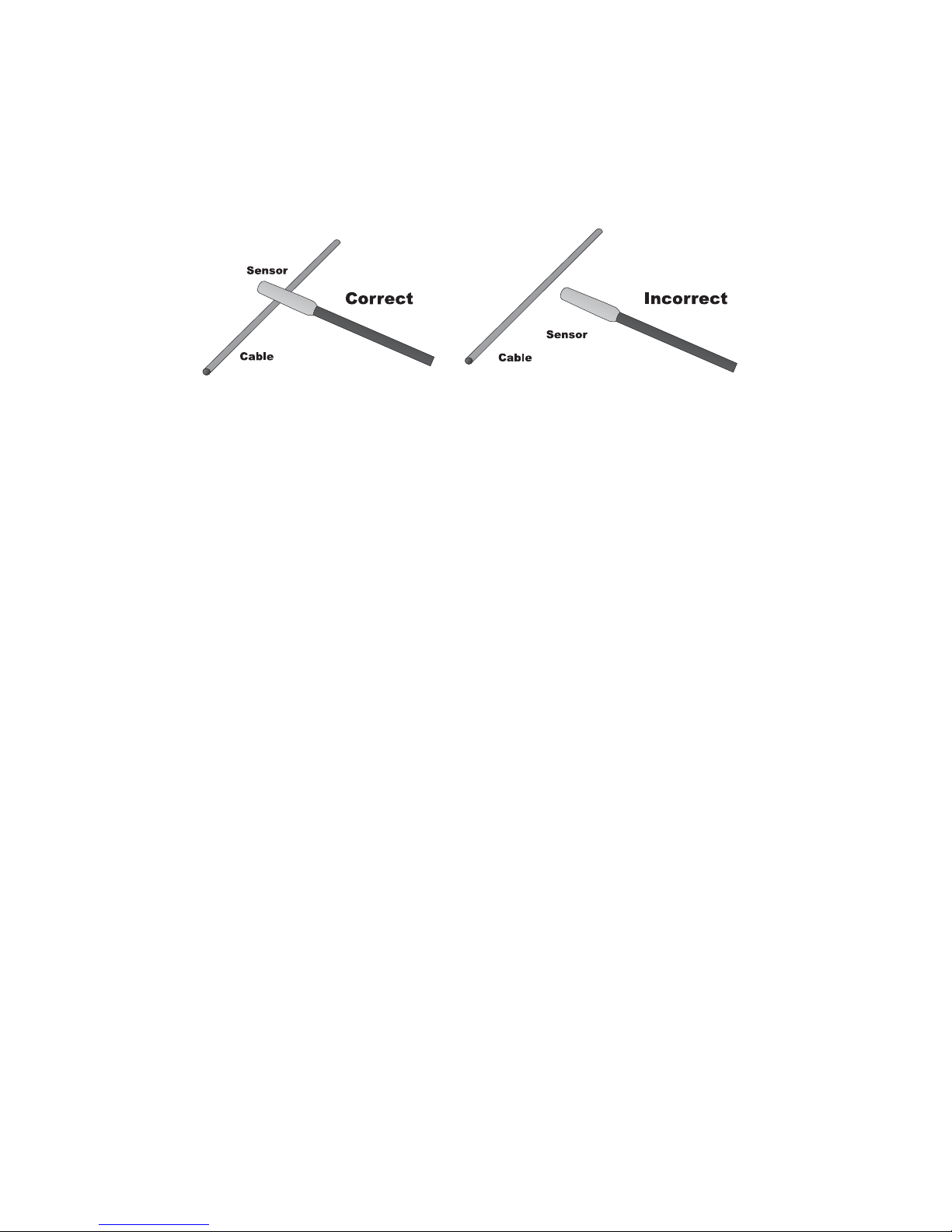
The probe of the FF310R is built of coiled steel equipped with a sensor (yellow
cylinder), and can be bent as needed, in order to reach wires in congested
or difficult areas. Depending on the circuit characteristics and the sensitivity
setting, the probe’s sensor will pick-up the signal from the wire in a wide range of
positions . However for the best possible range, the FF310R’s sensor (yellow cylinder)
should be positioned perpendicular ( at 90°) to the wire being traced and either above or
below it, as shown in Fig. 1 below.
Fig. 1 - Sensor positioning
6 - Locating Short Circuits
Refer to the Hook Up Reference Chart in Page 6.
6.1 Observe the limits and safety precautions at all times (refer to the beginning of
this handbook).
6.2 Connect the FF310T in series with the short-circuited wire, making sure one
of the unit’s clips is connected to the circuit’s positive supply (or vice versa for
vehicles with positive supply connected to chassis). A fuse socket connector (in place of
the blown fuse), a connector, etc., provides a convenient hook up as shown in Fig. 2 and
Fig. 3 in Page 6.
6.3 Switch the FF310T on by pressing the On/Off button and observe if the red LED on
the FF310T starts fl ashing. If not check the connections, power supply, and in the
case of having connected the unit to any place other than the fuse socket, check
that the circuit’s fuse is installed and in working condition (not open). If necessary
replace with a new fuse with the same ratings.
6.4 Switch the FF310R on, insuring the green LED turns on.
6.5 Verify that the FF310R is set to the lowest sensitivity level (single green
LED fl ash).
6.6 Slowly sweep the wire, conduit, etc., ensuring the FF310R’s sensor is
perpendicular and above or below the wire being traced and as close as
possible to it .
6.7 Follow the wire or check it at different points, starting from the FF310T and moving
towards the load (accessory, light , etc.) observing the positioning of the sensor as
indicated above. Continue this procedure while the audio signal (beeping sound) and
visual signal (fl ashing red LED light) indicates the integrity of the circuit. If beeping
and fl ashing slows down or stops it indicates that the sensor is either moving away
from the faulty wire or it has passed beyond the short circuit point.
6.8 If diffi cult or impossible to get the FF310R to pick-up any signal, then increase the
sensitivity level, and start again from step 6.6.
6.9 Double check positioning the sensor before and after the suspected place. If the
short circuit point has been located, the audio/visual indicators will show circuit
integrity on for one position, but not for the other.
Page 6

Page 4
6.10 The short circuit is located in the area where the audio/visual signal stops or
changes signifi cantly.
6.11 When the test is completed, switch off the FF310T unit pressing the On/Off button
and disconnect from circuit.
Note: The closer the FF310R’s sensor is to the wire carrying the signal, the faster the
beeping and the fl ashing will be. Some times it will prove advantageous to reduce
the sensitivity level to pint point more accurately the faulty area.
7 - Wire tracing
Wire tracing hook up and procedures are essentially the same as for locating short
circuits. The FF310T sees the load (light bulb, accessory, etc.) as a weak short circuit or
connection to ground. For wire tracing simply follow the wire with positive (beeping and
fl ashing) audio/visual indicator’s feedback on the FF310R from source to load.
For step by step directions please refer to point 6– Locating Short Circuits, for some
hints and specifi c differences refer to the notes below:
The type and size of load connected to the circuit (impedance or resistance to ground)
determines the amount of current allowed to fl ow in the circuit. Small loads (low Watt-
age lamps, electronic systems, etc.) will reduce the range of the FF310R accordingly.
In cases where the full range of the FF310R is required to follow the wire, it may prove
advantageous to use one of the two methods described below:
•
Tracing wires downstream (from supply to load): replacing the load for a full short
circuit allows the FF310R to work at its maximum capabilities. Before proceeding,
remove all electrical power from the circuit, connect the FF310T in series with the
wire to trace, short circuit the load to ground (refer to Hook Up Reference Chart
Fig.2 and 3), then reconnect power and follow instructions in section 6 – Locating
Short Circuits.
•
Tracing wires upstream (from load to supply): If more convenient, wires can also be
traced the other way around, by replacing the load with the FF310T (Fig. 5 of Hook Up
reference chart). To do this, fi rst remove power from the circuit, disconnect the load
and connect the FF310T in its place. Apply power to the circuit and follow instructions
in section 6 – Locating Short Circuits.
8 – Locating Current Leaks
Hook up and procedures for locating current leaks are essentially the same as for
locating short circuits. The FF310T sees the leak as a weak short circuit or
connection to ground. For locating a current leak simply follow the wire with positive
(beeping and fl ashing) audio/visual indicator’s feedback on the FF310R, from source to leak
location (short circuit).
For step by step directions please refer to point 6 – Locating Short Circuits, for some
hints and specifi c differences refer to the notes below:
Current leak notes:
•
The type and size of the leak in the circuit (impedance or resistance to ground)
determines the amount of current fl owing in the circuit. Small leaks (i.e. low current)
will reduce the range of the FF310R accordingly. In all cases the FF310R’s sensor
should be positioned as close as possible to the wires, in order to maximize the signal
captured by the FF310R, and set to a higher sensitivity level . For hook up refer to the
Hook Up Reference Chart Fig. 2 and 3 in Page 6.
Page 7

Page 5
9 - Locating Open Circuits
Refer to the Hook Up Reference Chart in Page 6.
9.1 Observe the limits and safety precautions at all times (refer to the beginning of
this handbook)
9.2 Connect the FF310T in series with the open ended wire, making sure one of the
unit’s clips is connected to the circuit’s positive supply or ground . A fuse socket
(with the fuse removed), a connector, etc., provides a convenient hook up as shown
in Fig. 2, 3, 4 and 5 of the Hook Up Reference Chart.
9.3 Make sure that the clips are fi rmly attached to their connection points, and switch
the FF310T on by pressing the On/Off button. Observe if the green LED on the
FF310T starts fl ashing. In the case of having connected the unit to any place
other than the fuse socket, check that the circuit’s fuse is installed and in working
condition (not open). If necessary replace with a new fuse with same rating.
9.4 Switch the FF310R on, insuring the green LED turns on and set if
necessary the sensitivity level to “LOW”.
9.5 Slowly sweep the wire with the FF310R, ensuring the sensor is perpendicular to
and above or below the wire being traced and as close as possible to it .
9.6 Follow the wire or check it at different points, starting from the FF310T and
moving towards the load (accessory, light, etc.), observing the positioning of the
sensor as indicated above. Continue this procedure while the audio signal (beeping sound) and visual signal (fl ashing green LED light) indicates the integrity of
the circuit. If beeping and fl ashing slows or stops, it indicates that the sensor is
either moving away from the wire or it has passed beyond the open, break or bad
connection in the circuit.
9.7 If diffi cult or impossible to get the FF310R to pick-up any signal, then increase the
sensitivity level and start again from step 9.5.
9.8 Double check by positioning the sensor before and after the suspected place. If
the open circuit point has been located, the audio/visual indicators will show circuit
integrity on one side, and not on the other.
9.9 At this point, where the audio/visual signal stops, you have found the open circuit.
9.10 When the test is completed, switch off the FF310T unit pressing the On/Off button
and disconnect from circuit. Y ou may also switch off the FF310R by pressing the On/
Off button on the unit. However to conserve power, the FF310R will automatically
turn off after 3 minutes of not being used.
Note: The closer the FF310R’s sensor is to the wire carrying the signal, the faster the
beeping and the fl ashing will be.
10 - Wire identifi cation
Refer to the Hook Up Reference Chart in Page 6.
Wiring can be identifi ed by following the hook up and procedures for locating short circuits
or open circuits, depending on the particular confi guration of the circuit.
•
For identifying wires with load connected: Connect the FF310T as described
in section ‘6- Locating Short Circuits’ to the circuit to be identified, then
proceed to scan all suspected wiring with the FF310R’s sensor until the fl ashing and
beeping is at its maximum. In the case of tightly packed wires ( bundles, conduits, etc.),
it may be necessary to spread these apart to facilitate the identifi cation process of
a particular wire.
Page 8
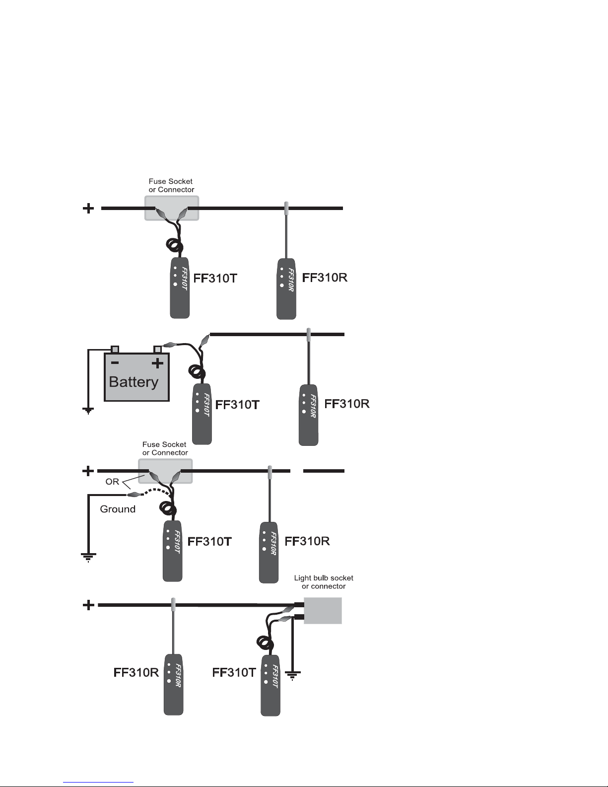
Fig.2 - Set up for tracing short
or open circuits, or
location of wiring
Fig.3 - Set up for tracing
short and open
circuits, or tracing
wiring
Fig.4 - Set up for tracing
open circuits or identifi cation of wires
Fig.5 - Set up for upstream
tracing of open
circuits or location of
wires
11- Hook up reference chart
Page 6
• For identifying wires without load connected: Connect the FF310T as
described in section ‘9- Locating Open Circuits’ to the circuit to be identifi ed, then
proceed to scan all suspected wiring with the FF310R’s sensor , until the fl ashing and
beeping is at its maximum. In the case of tightly packed wires ( bundles, conduits, etc.),
it may be necessary to spread these apart to facilitate the identifi cation process of
a particular wire.
Page 9
Page 7
12 - General Procedures
Short and open circuit operation – Differences:
The FF310 FaultFinder set uses two different types of signals to trace either short or open
circuits. Understanding its differences, as explained in the following paragraphs will allow
you to make the most effective use of this versatile tool.
12.1 Working with open circuits
On detection of an open circuit, the FF310T injects a special radio signal into the circuit,
which can be picked up by the FF310R’s sensor.
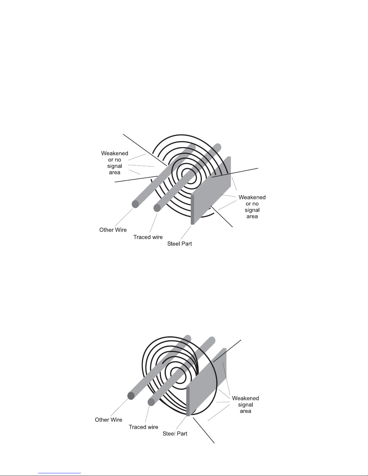
When tracing an open circuit, keep in mind that RF (radio frequency) signals injected in the
faulty wire being traced, will be easily absorbed by any other conductor nearby . (e.g.: other
wires, metal frames).The effect of this absorption may vary from a reduction in the FF310R’s
range, to a total shielding of the signal with no detection being possible at all (See Fig. 6).
Fig. 6 - Detection fi eld when tracing open circuit with the FF310R
In order to avoid confusing a shielded portion of the faulty wire with the actual fault on it,
the circuit should be checked on in several places to confi rm that no signal is detected
on the other side of the suspected faulty section.
12.2
Working with short circuits (and tracing circuits)
When the FF310T detects a short circuit (or closed circuit), it injects pulses of electrical
current in the wires, which generate magnetic fi elds. Unlike radio signals, magnetic fi elds
are not easily absorbed by nearby conductors and therefore can be picked up by the
FF310R’s sensor in a wider range of situations (See Fig. 7).
Fig. 7 - Detection fi eld when tracing short-circuits with the FF310R
Page 10

Page 8
12.3 Some circuit characteristics that may affect the tracing of a wire:
•
Electromagnetic loop size and geometry, etc. may affect the range of the
FF310R. For example for circuits in which the live and ground (return) wire run
parallel and close to each other in the same circuit, the two magnetic fields
interaction may weaken the signal, thereby reducing the FF310R range.
•
Wires enclosed or tightly lining the metal frame or body of the vehicle, (i.e.: door
frames), have the same effects as having the live and ground wires running in parallel
in the same circuit since, the metal frame or vehicle body will be acting as a ground
wire. Another unfavorable factor may be due to the channeling effect steel parts
have on magnetic fi elds. These two cases, individually or combined, will reduce and
sometimes impede the tracing of the wire sections affected.
Hint: Whenever possible the short circuit mode of operation should be used, because it
provides with the best tracing capabilities.
13 - Special Tracing procedures
•
In all cases, fi rst set the FF310R at the lower sensitivity level and increase it as
necessary. Proceed as indicated in the sections of this User’s Manual applicable
to your situation.
•
Always after locating a probable fault area, verify several points in the wires on both
sides (before and after) the suspected area. The signal should be present at only
one side of the fault (open or short). This procedure will help avoid confusing a signal
loss with the actual trouble point.
13.1 Wire bundles and conduits:
•
Special care should be given in the case of tracing a wire inside a bundle or
conduit when there is a split. In this case it may be possible to follow the wrong branch
for a short distance and still receive a positive audio/visual indication.
•
To avoid following the wrong path, which could happen if the FF310R’s sensor picks
up the signal from the other nearby branch of the circuit, the branches should be swept
maintaining the sensor outside the apex area between the split, as shown in Fig. 8.
•
Careful attention should be paid to the beeping and fl ashing speed of the FF310R
unit indicators, as these provide the necessary feedback to evaluate the proximity
of the sensor to the wire being traced.
Fig. 8 - Tracing Wires inside bundles and conduits
Trace with sensor
on this side
Trace with sensor
on this side
Wire bundle or conduit
Tracing inside this
area may generate
misleading results
13.2 How to increase the pick up range when tracing wires
•
When tracing or identifying wires connected to lightly loaded circuit (low
currents), this reduces the range of pick up signifi cantly. A possible solution is after
connecting the FF310T in series with the circuit to trace, is to replace the load (light
bulb, module, etc.) with a direct connection to ground. This allows the FF310T to
inject a more powerful signal which is easier to detect.
•
For the cases in which it is suspected the layout of the wires is the cause of a very
difficult to pick up or weak signal, a dramatic increase of the range can be
accomplished by “spreading” the circuit.
Page 11
Page 9
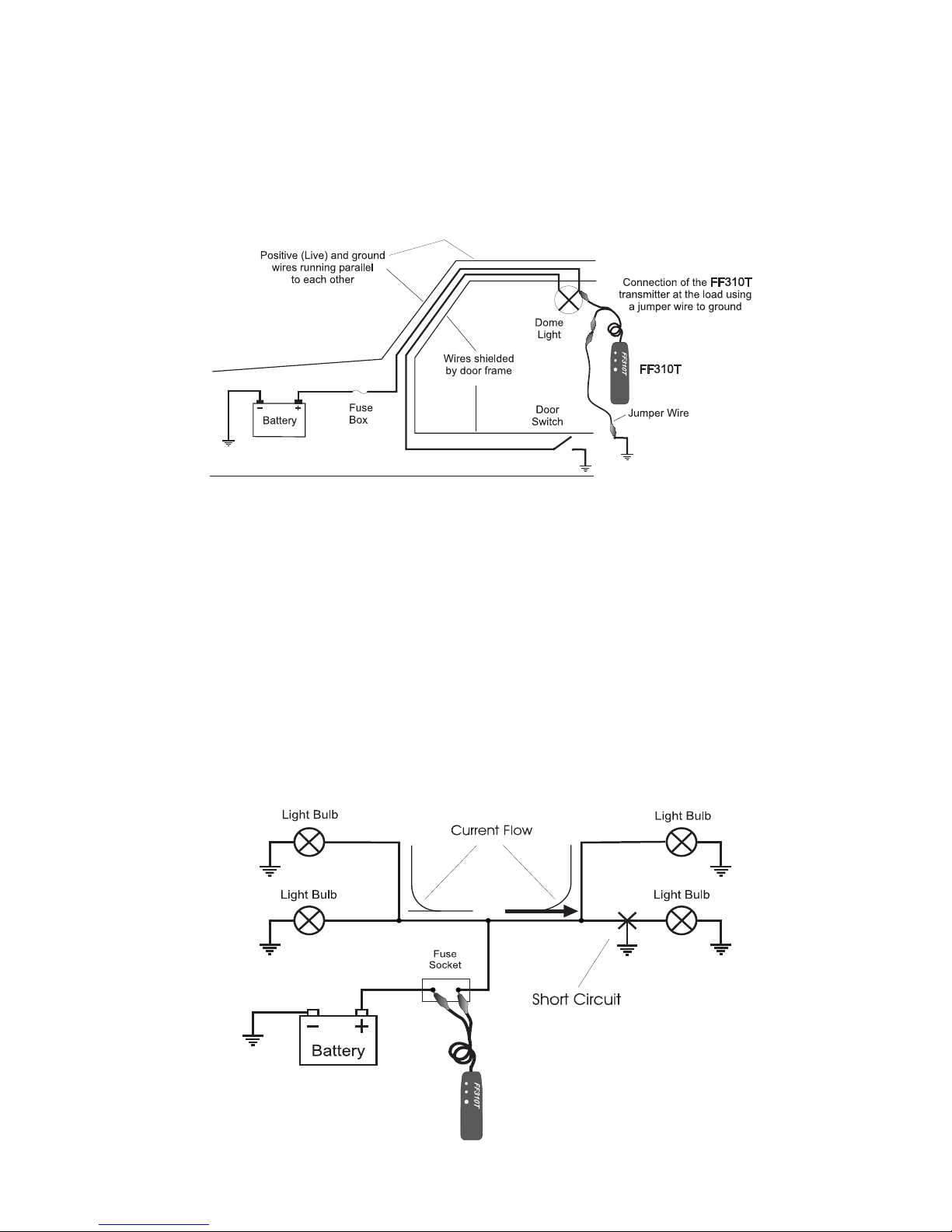
Fig. 9 - Simplified dome light circuit hook up for wire tracing
•
The spreading the circuit is achieved by connecting a jumper wire between the
live wire (preferably at a termination point in the circuit such as a light bulb socket,
switch, etc.), and a ground point somewhere else in the vehicle ( see Fig. 9). This
last method should be used only as “last resource” and with the FF310R set to low
sensitivity, as it could make the pinpointing of the precise location more diffi cult due
to the much increased range.
•
Always verify that the FF310T is connected in series with the circuit being tested and
that its red indicator light is on, as this confi rms a proper connection and will limit the
amount of current fl owing in the circuit.
13.3 Circuits with multiple loads or branches
•
When tracing circuits connected to, or which are powering multiple loads and/or
branches (See Fig. 10), and when these circuits are active or live, the bulk of the
current injected into the circuit by the FF310T will be directed to the shorted branch
of the circuit. However smaller amounts of current (or stray currents) will fl ow to the
other branches as long these provide a path to ground (i.e. close the circuit).
•
These stray currents present in the non-shorted branches of the circuit, and
depending on the circuit confi guration and physical layout of the wires, could
be picked up by the FF310R, making the tracing procedures confusing, and
even misleading.
•
The simplest and most effective way to deal with these cases, is to disconnect or
remove all the loads from the circuit being traced (i.e. removing light bulbs in
example shown in Fig. 10).
Fig. 10 - Schematic of a single circuit with multiples loads
Page 12
Page 10
14 - Technical specifi cations
FF310T -Transmitter
Voltage range: 6 to 42 volts DC.
Indicator: Flashing green LED indicator for power on or open circuits.
Flashing red LED indicator for short circuits.
Power source: 9 volt alkaline battery, Duracell MN1604 or equivalent.
Connector: Two 5 Amp. universal micro-clips with auto polarity and 18” long cable.
Battery life: Approximately 25 hours of use.
FF310R - Receiver
Sensitivity: 3 User selectable levels (Low, Medium and High)
Probe: Flexible 8” gooseneck insulated steel probe with sensor.
Indicator: Green LED indicator for Power On and Open Circuits. Red LED
indicator for short circuits. Audio signal for shorts and opens.
Variable fl ashing and modulated audible signal.
Power source: 9 volt alkaline battery. Duracell MN1604 or equivalent.
Battery life: Approximately 25 hours of use.
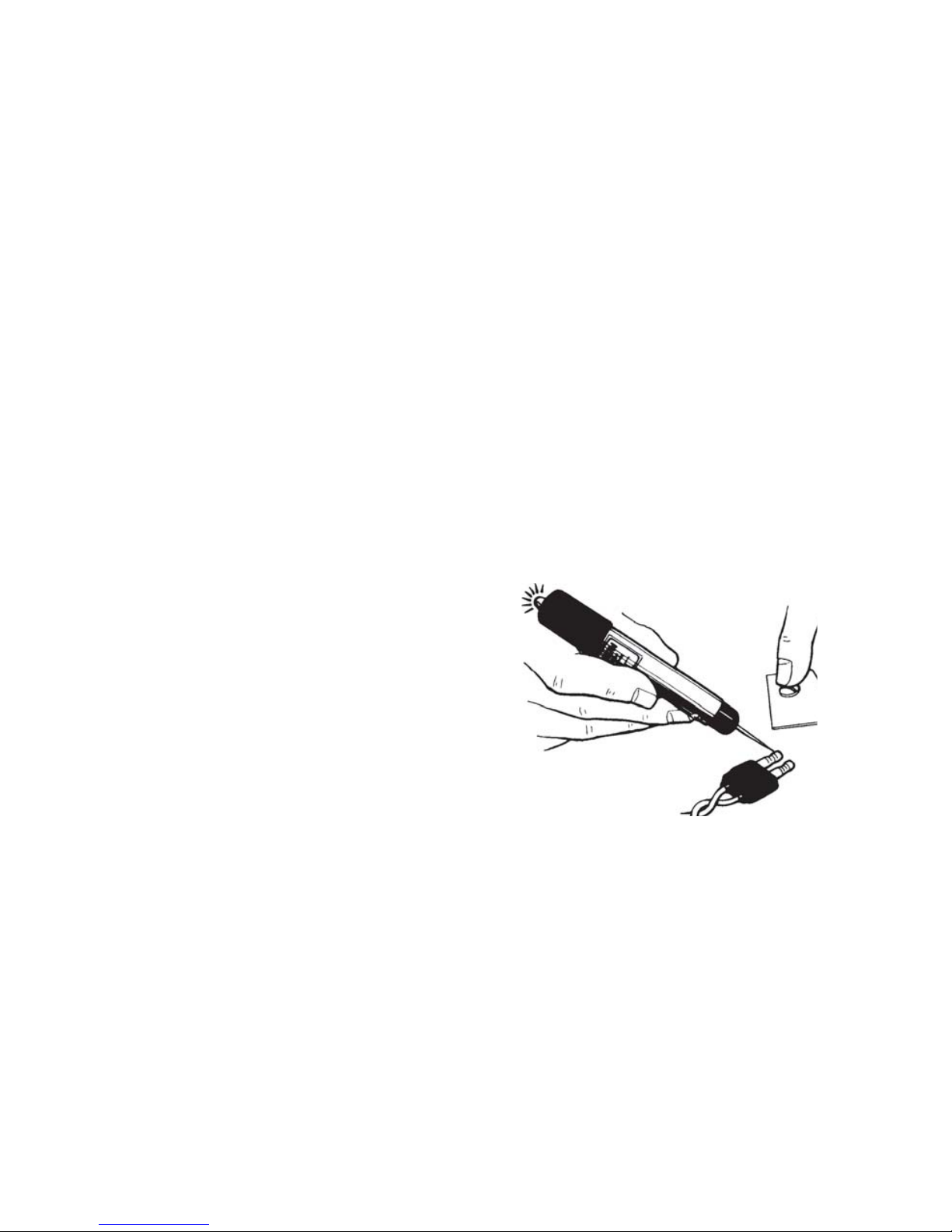
15 - CT8002AA Professional Circuit Tester
Instructions
1- Hold tester by metal barrel and place free
hand on bare (grounded) metal part of
the vehicle.
2- Place tester point into connector or wire
(pierce insulation if necessary).
3- Tester will emit a sound, vibrate, and the
red light turn on when a positive voltage is
detected.
V-Groove Protector Tip uses:
1- Always insert the V-Groove protector tip on the tester point before carrying or storing
the unit, as this may avoid injuries.
2- Use the V-Grove protector tip when piercing wires to prevent the tester point from
side-slipping on the wire and causing injuries or damage.
3- The protector tip may be removed for testing in hard to reach places inside connectors,
sockets, etc.
Replacing the battery:
The battery supplied with the tester will provide years of service under normal use. When the
sound, vibration, and light starts to fade, remove the screw and pull out the plastic pointer
assembly . Remove the battery and insert a new type IEC LR6 - ANSI/NEDA 15A (AA size
alkaline) or equivalent battery, observing the polarity (negative side goes in fi rst). Insert
the tester point assembly, then align the holes and replace the screw.
Page 13
Page 11
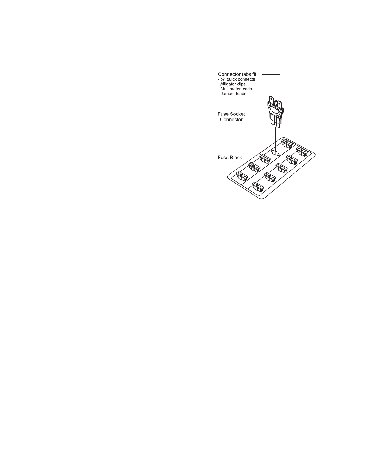
16 - CT6100 Fuse Socket Connectors
The CT6100 fuse socket connectors are designed to facilitate the connection of the test
leads of the FF310T to the circuit under test through the fuse box, and can also be used
for all other situations when access to the fuse socket connections are required. These
connectors are supplied in three sizes: Mini, ATO and Maxi.
How to use the CT6100 connectors
1- Choose the connector (Mini, ATO or Maxi) that
matches the fuse socket where the connection
is required.
2- Remove the power to the circuit.
3- Insert fuse connector into the socket (see fi gure).
4- Connect test leads to the connectors tabs of the
fuse socket connector.
17 - Care of the Unit
The FF310 is a precision instrument and should be treated as such. Damage caused by
mistreatment is not covered by the warranty.
Keep the units in their carrying case when not in use and do not subject to dampness or
severe heat or cold. Do not use the units in the rain, if they should accidentally get wet.
dry them off with a clean paper towel before storing away.
Protect the units from contact with any solvents. Never clean with a solvent or petroleum
based medium such as gasoline, as these chemicals may attack the plastic parts and
cause permanent damage. Never use an abrasive cleaner. Cleaning should be limited
to wiping with a clean damp paper towel with a small amount of soap if required. Dry the
units thoroughly after any cleaning.
These are sealed instrument and contains no user serviceable parts other than the
battery which can be replaced by opening the drawer on the back of the units. Opening
other parts of the units will void the warranty.
Page 14

Page 12
18 - Warranty
With the exception of the batteries, your FF310 is warranted against defects of
material or workmanship which develop within a period of one (1) year following the
date of purchase by the original owner. Proof of date of purchase will be required when
applying for repair or replacement under guarantee. For this reason, we strongly suggest
that you keep your sales receipt safely in your FF310 storage case.
In the event a fl aw develops in the FF310, please return it to your dealer who will ar-
range repair or replacement. The manufacturer will either repair or replace the tool
(at the manufacturer’s option) free of charge providing the FF310 is still under
warranty . If the warranty has expired, there will be a repair charge payable to your dealer
when you pick up the unit. When a unit has been repaired or replaced under warranty , the
replacement unit will continue the warranty period of the original unit for six (6) months
after the date of replacement or until the original warranty expires, whichever is the longest
period. This warranty shall not apply to any defect, failure or damage caused by improper
use or inadequate maintenance or care.
The manufacturer shall not be obligated to provide service under this warranty or to
repair damage resulting from attempts by unauthorized persons to repair or service the
FF310, other than to replace the battery; or to repair damage resulting from improper use.
Specifically if there is evidence of an attempt to open the FF310 the
warranty is void.
Any implied warranties arising out of the sale of the FF310 including but not limited to
implied warranties of merchantability and fi tness for a particular purpose are limited in
duration to the above one (1) year period, the manufacturer shall not be liable for loss
of use of the FF310 or other incidental damages, expenses or economic loss. Some
Jurisdictions do not allow limitations on how long implied warranties last or the exclusion
or limitation of incidental or consequential damages, so the above may not apply to you.
Page 15

Part # FF310MN1707EN
© 1996-2017 General Technologies Corp.
Printed in Canada
#121 - 7350 72nd Street Tel.: (604) 952-6699
Delta, BC Fax: (604) 952-6690
Canada V4G 1H9 email: [email protected]
“V Ready” and “GTC” are trademarks of General Technologies Corp.
To visit our website, scan the QR code below with your smart phone.
Or type this URL your browser:
www.gtc.ca
 Loading...