

CT8030
1. SAFE TY RULES
This meter is designed for indoor use at temperatures between 0°C to 40°C and
•
altitudes up to 2,000m.
To ensure that the meter is used safely, follow all safety and operating instructions in
•
this operation manual. If the meter is not used as described in this operation manual,
the safety features of this meter might be impaired.
Do not use the meter if the meter or test leads look damaged ,or if you suspect that
•
the meter is not operating properly.
When using the instrument, keep your fi ngers behind the fi nger guards on the plastic
•
casing and probes.
Disconnect the live test lead before disconnecting the common test lead.
•
Make sure power is off before cutting, desoldering, or breaking the circuit wires. Small
•
amounts of current can be dangerous.
Do not apply more than 1000 VDC or 750V AC rms between a terminal and ground.
•
T o avoid electrical shock, use CAUTION when working above 60V DC or 25V AC rms.
•
Such voltages pose a shock hazard.
Never make measurements with the battery cover off.
•
To avoid electrical shock or damage to the meter, do not exceed the input limits.
•
2. INTERNATIONAL SYMBOLS
Important information Dangerous Voltages
see manual Continuity
AC Ground
DC Double Insulation
3. TECHNICAL SPECIFICATIONS
3.1 General Specifi cations
Display: LCD, 4¾ digits/40000 Counts (99999 for Hz
function) + 4 Digits/9999 Counts dual display
with 42 segments analog bargraph.
Polarity: Automatic, (-) negative polarity indication
Zero adjustment: Automatic
Sample rates
3¾ Digits: 5 times per Sec.
4¾ Digits: 1.25 times per Sec.
43 Seg. bar graph: 128 times per Sec
Over range indication: “
Operating Temperature: 0 to 35°C, 0 to 80% RH
0 to 50°C, 0 to 70% RH
Power Source: 9-volt battery type NEDA 1604, IEC6F22
Battery life: Approx. 70 hours. (w/ alkaline batteries)
Safety: Designed to comply with EN61010-
E.M.C.: Meets EN55011 and EN582-1
Dimension: 7.32”x3.42”x1.39” or 186x87x35.5mm
without Holster
Weight: Approx. 13.8 Oz. or 390g (without Holster).
Accesories: User’s Manual, Test Leads, Back Probes,
OL” is displayed
1, UL3111-1, CSA C22.2 No.1010-1
and IEC1010-1 Installation category II,
Pollution degree 1
Alligator Clips, Protective Holster, Hard
Carriying Case, K-type Temperature Probe,
Inductive pick-up and 9V battery.
Page 1
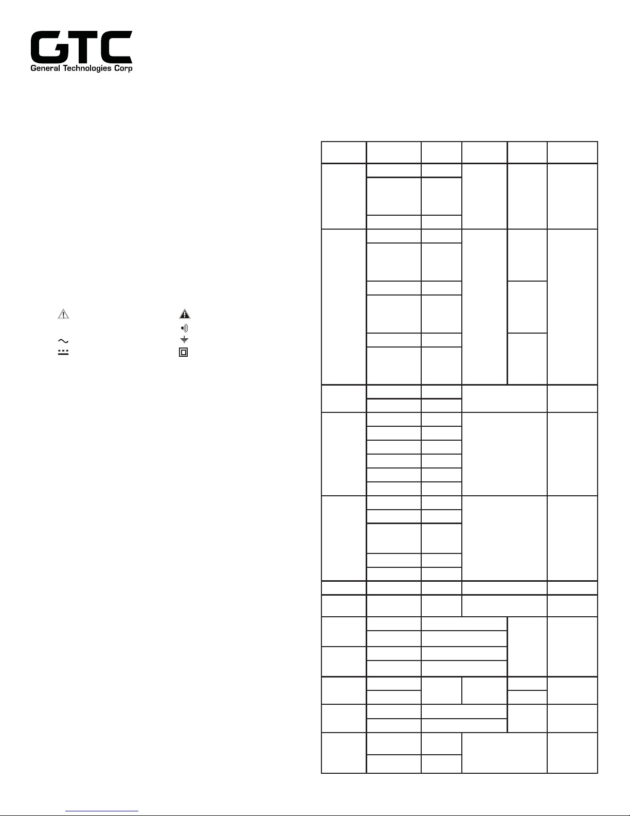
3.2 Electrical Specifi cations
Accuracies are ±(% of reading + number of least signifi cant digits) at 23°C
•
±5°C, less than 75% RH. For DC/AC current measurement, the maximum
current of 10 A is for 30 Sec. with 5 min. cool down between measurements.
Function Range Accuracy
40.00 mV 0.8%+6
400.0 mV,
DC Voltage
AC Voltage
DC Current
AC Current
Resistance
Diode Test
Frequency
Multiport
Fuel
Injection
Single
Port Fuel
Injector
Tachometer
Dwell
Temperature
4.000 mV,
40.00 V to
400.0 V
1000 V 0.1%+4
40.00 mV 1%+10
400.0 mV,
4.000 V,
40.00V,
400.0 V, 750V
40.00 mV 3.5%+10
400.0 mV,
4.000 V,
40.00V,
400.0 V, 750V
40.00 mV 4%+10
400.0 mV,
4.000 V,
40.00V,
400.0 V, 750V
4000 mA
10.00 A
4000 mA
10.00 A
4000 mA
10.00 A
4000 mA
10.00 A
40.00
400.0
4.000 k
40.00 k
400.00k
4.000 M 0.3%+2
40.00 M 1.5%+3
2.000 V - < 3.2 V Test Voltage 600 Vrms
99.999 Hz to
20.000 kHz
0.05 - 250 mS
0.0 - 100 %
0.05 - 250 mS 0.05mS+1
0.0 - 100 %
120-20000 RPM
60-10000 RPM RPM 2
0.0º - 360.0º 1.2º/krpm+1
0.0º - 100.0º 0.04º/krpm/cyl +2
-20.0º to
1000.0ºC
-4º to 1832ºF 0.2%+6ºF
0.1%+2
0.8%+4
2.5%+5
3.6%+8
1.2%+6
0.8%+4
1.2%+6
1.0%+3
2.5%+10
1.2%+3
3.5%+10
1.5%+5
0.5%+40
0.15%+4
0.15%+2
0.001%+4
0.04%/krpm +2
0.04%/krpm/cyl +2
2 RPM
02%+3ºC
Input
Impedance
10 M
30 pF
nominal
10 M
30 pF
nominal
(100pF
nominal in
40 mV and
400 mV
Ranges)
0.03 V/A Voltage Burden
0.03 V/A Voltage Burden
<1.3 V Test Voltage
(<3.3 V in 40
400
range)
1, 2, 20 and 200 Vrms
Selectable threshold
0.05mS+1
K-Type Thermocouple
Probe
Remarks
50~60Hz
40 Hz to
1 kHz
1 kHz to
2 kHz
and
Selectable
+/- Slope,
and
Number of
Cylinders
RPM 4
1 to 12
Cyl.
Overload
Protection
600 Vrms
600 Vrms
Protected
Protected
600 Vrms
600 Vrms
600 Vrms
600 Vrms
600 Vrms
600 Vrms
Fuse
Fuse
Audible Continuity Tester
RPM
4
RPM
2
Audible threshold : between 10, and 60.
•
Response time: 200μs.
•
O
Sensor Tester
2
Application : For O2 Sensor dynamic test
•
Main Display : Symbolic waveform display of O2 Sensor
•
Mini display : Cross count per second parameter.
•
Sweep Rate : 10 per second.
•
Alternator tester
Application : For quick go / no go test on alternators
•
Threshold : The display indicates "bad" and the
•
Fault Code Detector
Application : For blink type fault code detection
•
Display : The display indicates a symbolic pulse and
•
Threshold : 4.5VDC with selectable positive or negative
•
dynamic output.
A beep sound will alert the user on each
signifi cant cross count edge
beeper turns on when the measured
ripple voltage is greater than 0.45VAC.
the beeper turns on when the blink code
pulse is detected.
pulse trigger (by ±Trigger button).
DTC (Diagnostic Trouble Code) Decoder
Application : A replacement of the Impulse Counter Scan
•
Tool as specified in the Mercedes-Benz
Diagnostic Trouble Code Reference Guide
to scan the DTC Code readout automatically
on the Mercedes-Benz car series.
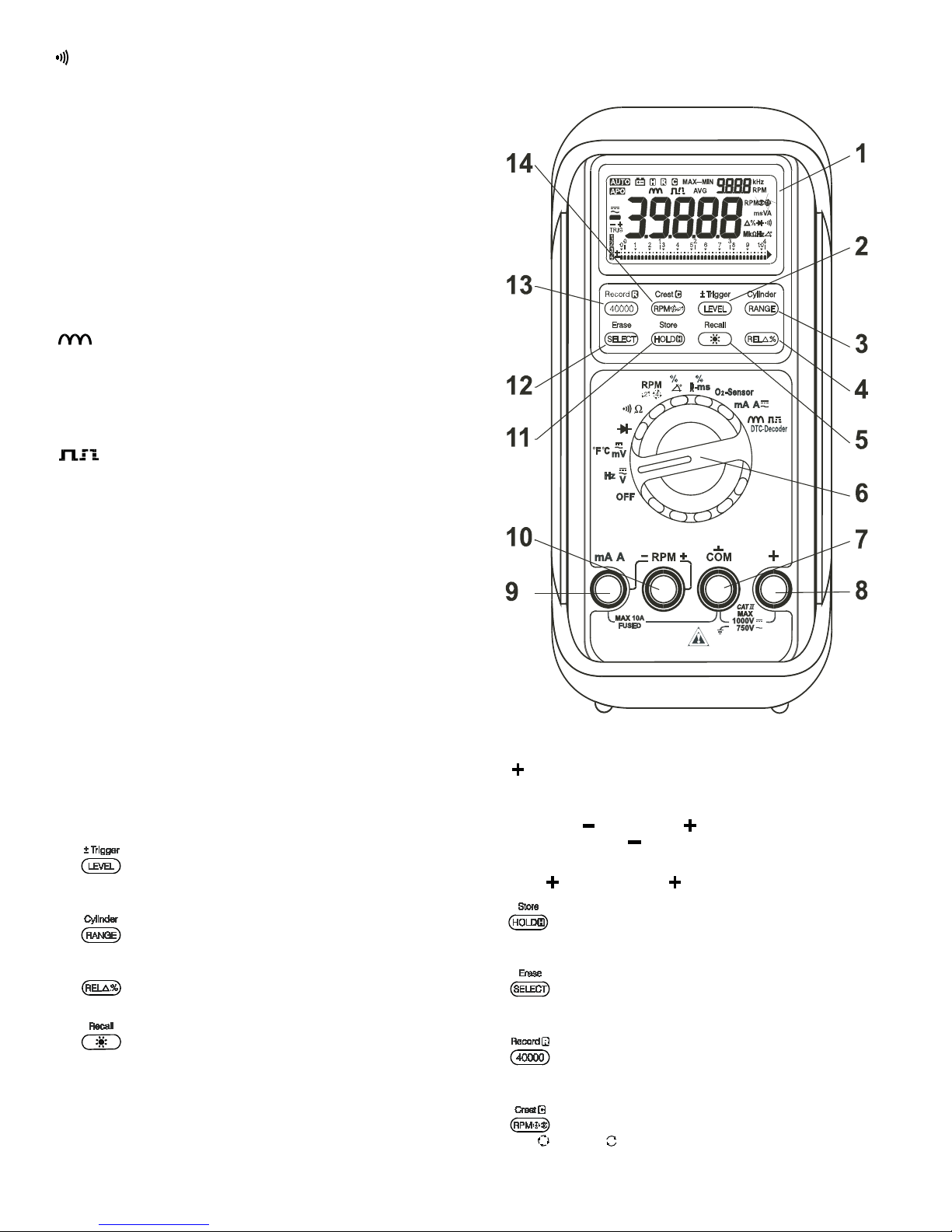
4. OPERATION
4.1 Instrument Description
1- LCD Display: 4-3/4digit 40000 count 4 digits 9999 count dual display.
2-
3-
4-
5- : Pushbutton. Press momentarily to turn on the display
6- Rotary Switch: Turns the power ON and OFF and selects
7- COM Input Socket: Common (Ground Reference) Input
: Pushbutton, press momentarily to select trigger levels,
or press and hold for 1 second to toggle between positive and
negative trigger slopes.
: Pushbutton to select Auto/Manual ranging in most
functions, or number of cylinders in Dwell function.
: Pushbutton to select relative zero and relative
percentage change.
backlight, or press and hold for 1 second to recall stored data.
measuring functions.
connector for all functions except TACH function.
8- : Input Socket for all functions except Current and TACH
functions.
9- mA A/RPM
ground reference (
10- RPM
11-
12-
13- : Pushbutton. press momentarily to toggle between
14- : Pushbutton. press momentarily to toggle between
Page 2
: Pushbutton. Press momentarily to activate hold, or
press and hold for 1 second to store the data displayed for
later recall
: Pushbutton. press momentarily to select secondary
functions, or press and hold for 1 second to erase all stored
datas
40,000 and 4000 counts modes, or press and hold for 1
second to activate record function
and
second to activate Crest function
: Input Jack ( ) for current function, and
) input Jack for RPM function.
: INPUT JACK ( ) FOR RPM FUNCTION
in RPM function, or press and hold for 1
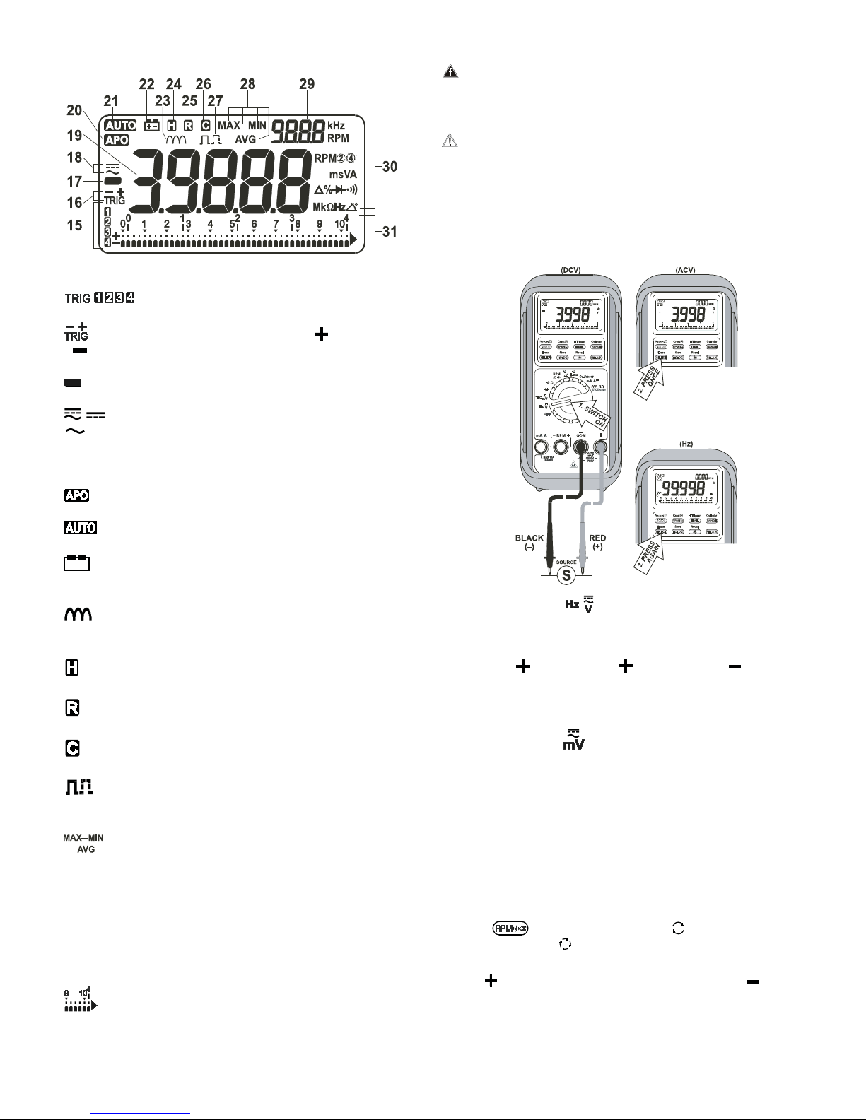
4.2 Display Description
2
4
15. : These annunciators indicate trigger level status.
16. : These annunciators indicate positive ( ) or negative
( ) Trigger Slope is selected.
17.
: Negative polarity symbol.
:
annunciator indicates direct current (DC) is selected.
18.
annunciator indicates alternating current (AC) is selected.
4.3 Measurement Procedures
CAUTION: Maximum Input Voltage is 750Vrms,do not exceed
this rating to avoid personal injuries or damage to the
instrument. The FUNCTION switch should be set to
the range you want to test before the operation.
CAUTION: Always ensure that the correct terminals are used for
the type of measurement to be made. Avoid making
connections to “live” circuits whenever possible.When
making current measurements ensure that the circuit
is not “live” before opening it in order to connect the
test leads.
4.3.1 DC/AC Voltage Measurement
19. DATA : Main digital readings of data being measured.
20.
21.
22.
23.
24.
25.
26.
27.
28.
29. DATA : Secondary display for Dual Display data.
30. kHz : These annunciators indicate the function being selected
31.
: This annunciator indicates Auto Power Off is enabled.
: This annunciator indicates Autoranging.
: Low Battery alert, replace the battery as soon as possible
to ensure accuracy.
: This annunciator indicates the Alternator tester function
is selected.
: This annunciator indicates data HOLD function is activated.
: This annunciator indicates the Record function is activated.
: This annunciator indicates the Crest function is activated.
: This annunciator indicates the Fault Code Detector
function is activated.
: This annunciators indicate MAX (Maximum), MIN
(Minimum), MAX-MIN (Maximum minus Minimum), or AVG
(Average) reading is being displayed.
and/or the appropriate measurement units.
: Analog bar graph with overload fl ag, polarity and scale.
Set rotary switch to position.
•
Default at DC. Press SELECT button momentarily to select AC,
•
and press again to select Hz if required.
Insert red ( ) test lead into jack and black ( ) test lead into
•
COM input jack.
Connect test leads to voltage source and observe the digital
•
display for the readout.
Set rotary switch to position for voltage application below 0.4V
•
with similar operation procedures.
Refer (4-2) for enabling dual display RPM function.
•
Hz Function: 4 trigger levels selectable through the LEVEL push
button for advanced applications in this function. Also refer to section
5.8 of this manuals for more details.
4.3.2 DUAL DISPLAY RPM Function
Set the meter to the corresponding primary function. See note
•
below for function availability.
Press button to toggle to
•
engine, or to
Insert output plug of inductive pick up with the positive (red) into
•
RPM
Clamp the inductive pick up to a spark plug wire with the arrow
•
sign facing the spark plug. Make sure that the pick up jaws are
completely closed.
Observe the secondary digital display for RPM readings.
•
Page 3
jack and the negative (black) into the RPM jack.
for 4-stroke engine.
for 2-stroke and DIS

Note: 1- This function is available to primary functions: DCV, ACV,
Hz, Dwell, Fuel injection detector, & Duty cycle.
2- When trigger level selection is required for advanced
applications, use main display RPM function. See (4.3.6)
for more details.
4.3.3 TEMPERATURE Function
DIODE TEST function
4.3.4
Set rotary switch to .
•
Insert red ( ) test lead into jack and black ( ) test lead into
•
COM input jack.
Connect the test leads as shown and observe the digital display.
•
Normal forward voltage drop (forward biased) for a good silicon
•
diode is between 0.400V to 0.900V. A reading higher than that
indicates a leaky diode (defective). A zero reading indicates
a shorted diode (defective). An ‘OL’ indicates an open diode
(defective).
Reverse the test leads connections (reverse biased) across the
•
diode.
The digital display shows ‘OL’ if the diode is good. Any other
•
readings indicate the diode is resistive or shorted (defective).
Temperature Probe
Set rotary switch to position
•
Press SELECT button momentarily two times to select temperature
•
function.
Without any temperature probe plugged into the input terminals
•
(detect automatically by the meter), the secondary digital display
displays the meter internal temperature reading in °C & °F
alternatively.
Insert the banana plug type-K temperature bead probe (standard
•
accessory) with correct
jack where negative ( ) plugs into COM input jack. You can
also use a plug adapter (optional accessory) with banana pins
to type-K socket to connect other standard type-K mini plug
temperature probes.
polarities. Positive ( ) plugs into
4.3.5 RESISTANCE, CONTINUITY Functions
CAUTION: Maximum Input Voltage for this function is 600 Vrms
do not exceed this rating to avoid personal injuries or
damage to the instrument. Also ensure there is no
power applied to the component or circuit and all
capacitors are discharged.
Touch the end of the thermo probe to the measurement surface
•
and observe the digital display with °C in the main display, and °F
in the second display.
Set rotary switch to
•
Insert red ( ) test lead into jack and black ( ) test lead into
•
COM input jack
Page 4

Connect the test leads as shown and observe the digital display.
RPM
4
2
RPM
2
RPM
4
•
Default at . Press SELECT button momentarily to select
•
Continuity function.
A continuous beep tone indicates a complete wire. This is useful
•
for checking wiring connections and operation of switches.
4.3.6 RPM function (main display)
Set rotary switch to .
•
Default at 4 cylinders ( ). Press cylinder (RANGE) button
•
momentarily to display the cylinder setting on the secondary
display, and press momentarily again within one second to select
the number of cylinders from 1 through 12 to match the engine
under test.
Insert red ( ) test lead into jack and black ( ) test lead into
•
COM input jack.
Connect the test leads as shown and observe the digital display.
•
Press SELECT button momentarily to display DWELL reading in
•
terms of percentage if required.
Refer (4-2) for convenient dual display RPM function.
•
Adjust the dwell angle according to the procedures outlined in your
•
vehicle service manual.
Note: 1- Re-check the timing whenever the dwell angle has been
adjusted.
2- 4 trigger levels selectable through LEVEL push button for
advanced applications in this function. Also refer (5-8) for
more details.
4.3.8 FUEL INJECTION DETECTOR Function
Set rotary switch to .
•
Press
•
engine, or to
Insert output plug of inductive pick up with the positive (red) into
•
button to toggle to
for 4-stroke engine.
for 2-stroke and DIS
RPM jack and the negative (black) into the RPM jack.
Clamp the inductive pick up to a spark plug wire with the arrow
•
sign pointing the spark plug. Make sure that the pick up jaws are
completely closed.
Observe the digital display for RPM readings.
•
Note: 4 trigger levels selectable through LEVEL push button, for
advanced applications in this function. Also refer (5.8) for
more details.
4.3.7 DWELL Function
Set rotary switch to -ms.
•
Insert red ( ) test lead into jack and black ( ) test lead into
•
COM input jack.
Connect the test leads as shown and observe the digital display.
•
Press SELECT button momentarily to display ms reading in terms
•
of percentage (%) if required.
Refer (4-2) for convenient dual display RPM function.
•
Note: 1. This
-ms function applies to both Port Fuel Injectors (PFI)
which operate with a single on time pulse and Throttle Body
Injectors (TBI) which operate with twin pulses.
2. 4 trigger levels selectable through LEVEL push button for
advanced applications in this function. Also refer (5.8) for
more details.
3. The fuel injection frequency can be displayed on the
secondary display by pressing the
button.
Page 5

4.3.9 O2-SENSOR TESTER Function
Set rotary switch to O2 -Sensor position.
•
Insert red ( ) test lead into jack and black ( ) test lead into
•
COM input jack.
Connect test leads to the O2 sensor dynamic output and observe
•
the digital display.
The main digital display shows a symbolic waveform of the O2
•
sensor dynamic output.
The secondary digital display shows the cross count per second
•
parameter, and a beep sound will alert the user on each cross
count edge being detected. Nominal cross count number is 1 to
3 for a good O2 sensor. The higher the cross count number, the
more active the O2 sensor is.
4.3.9 mA and A Functions
CAUTION: Do not measure any circuit that draws more than
the current rating of the protection fuse. If the fuse
blows, replace it with the proper fuse. Failure to
do this may result in injury or damage to the meter.
Do not attempt a current measurement where the
open circuit voltage is above 600V. Suspected
open circuit voltage must be checked with voltage
functions. Voltage output current clamp adaptors
are recommended to use with the meter voltage
functions for making high current measurements.
Set rotary switch to mA A .
•
Insert red ( ) test lead into mA A jack and black ( ) test lead
•
into COM input jack..
Defaults at DC. Press SELECT button momentarily to select AC.
•
Connect the test leads as shown and observe the digital display.
•
4.3.10 ALTERNATOR TESTER Function
Set rotary switch to
•
Insert red ( ) test lead into jack and black ( ) test lead into
•
COM input jack.
Start the engine and operate it at about 2000 rpm.
•
Connect the test leads as shown and observe the digital display.
•
A reading of 0.45V (typical) or less indicates that the alternator and
•
the associated rectifi er diodes are in good condition, and ‘good’ will
be displayed on the LCD. A display ‘bad’ together with continuous
beep sound indicate any of the following faults may exist:
- Defective rectifi er diode(s).
- Defective Alternator coils.
- Opened coil or rectifi er connections.
- Neutral of 3-phase Y-connection alternator accidentally
grounded to chassis.
4.3.11 FAULT CODE DETECTOR Function
Set rotary switch to DTC-Decoder.
•
Default at . Press SELECT button momentarily to select
•
Insert red ( ) test lead into jack and black ( ) test lead into
•
COM input jack.
Page 6

Connect the test leads to the fault code signal pins of the diagnostic
•
socket and then trigger the fault code output.
Typical fault code output triggering procedure is to short (close
•
circuit) the two trigger pins of the diagnostic socket and then turn
the ignition key to the ON position. DO NOT start the engine.
Location of the diagnostic socket, signal pins assignment, signal
•
type, and procedures of triggering & clearing the fault code may
be varied with car models. Consult your vehicle service manual
for manufacturer's specifi cations. The display indicates a symbolic
pulse and the beeper turns on when the blink code pulse is
detected.
Time interval between pulse signals and duration of pulse signal
•
represent the blink type fault code numbers.
As an example, some car manufacturers use long pulse for the fi rst
•
code digit, and short pulse for the second code digit. In this case,
2 long 'Beeps' followed by 5 short 'Beeps' represented
fault code
number 25. As another example, some car manufacturers use
same time interval between pulse signals on the same code digit,
and with longer time interval to separate the code digits. In this
case 2 short 'Beeps' followed by a quiet interval and then followed
by 5 short 'Beeps' represented fault code number 25.
Please note that in some car models, fault code signal output is
•
preceded by leading pulse signals.
As a typical procedure for clearing the fault code stored in the
•
memory. Turn the ignition key to the OFF position. Disconnect the
negative (
) battery terminal from the car electrical system for
about 1 minute, and the fault code will be cleared from memory.
Some car models require specifi c procedure to clear the fault code
stored, consult your vehicle service manual for details.
4.3.12 DTC-DECODER Function
6- Trigger the DTC readout by Shorting (close circuit) the 2 signal
pins of the data link connector for about 4 seconds until the
secondary LCD shows "
". Then the meter is ready to scan
the DTC readout automatically.
7- During scanning the meter secondary display indicates a pulse
symbol "
", and the beeper turns on when a DTC pulse is
detected.
If the DTC scanning is not successful, the meter secondary
display will indicate "
" to alert the user. Re-check the wire
connections, and start the trigger process again.
If the DTC scanning is successful, the meter secondary display
will indicate code "
" with 4 beep sounds, and the main
display indicates the correct DTC readout.
8- Read and note DTC readout displayed on the LCD Display "1" =
no fault stored, Greater than "1" = fault in system.
9- Repeat procedure in step 6. If there are no further faults in the
system, the previously displayed DTC will be displayed.
10- Repeat procedure in step 9 until the fi rst DTC displayed is
repeated.
11- Eliminate (repair) all noted faults (DTC readout) of the car
according to troubleshooting chart and diagnostic tests.
12- After eliminating a fault, the respective DTC may be cleared
by repeating procedure on step 6 to get the DTC readout, and
then short the 2 signal pins for another 6 to 10 seconds, then
the DTC displayed is cleared. Please note that each DTC
displayed must be cleared individually.
*Note: Consult your Mercedes Benz Diagnostic Trouble Code
Reference Guide for signal pins assignments and engine
precondition procedures before triggering the DTC readout. They
might be different from car model to model, and function to function.
1- Set rotary switch to DTC-Decoder
- Default at . Press SELECT button two times to select
2
DTC-Decoder
3- Insert Red (
) test lead into jack and black ( ) test lead
into COM input jack
4- *Connect the test leads to the signal pins of the data link
connector. This function is a replacement of the impulse counter
scan tool with wire connections COM for black (bk), and
for yellow (yw) as specifi ed in the Mercedes-Benz Diagnostic
Trouble Code Reference Guide. Since the meter is powered by
internal battery, connection of the impulse counter red (rd) wire
(to B+) for external power is not required
5- *Set Engine at idle
Page 7
5. ADVANCED OPERATION
See table below for feature availability on each function.
Data
Range
40,000
Function
DC Voltage
AC Voltage
Temperature
DC Current
AC Current
Resistance
RPM
Frequency
Duty Cycle
-ms
Dwell
O2 Sensor
Continuity
Diode
Alternator Test
Fault Code
DTC Decoder
Lock
Hold
••• ••• ••
••• ••• ••
••• ••• •
••• ••• •
••• •• •
•••••
••••••
•••••••
•••••••
•••••••
•••
•••• •
•••• •
•••
•••
•••
Relative Record
Count
••• ••
5.1 40,000 COUNTS HIGH RESOLUTION Mode
Press the button momentarily to enter the 4-3/4 digit high
resolution slow mode with a maximum display at 40,000 counts.
Press the button momentarily again to return to 3-3/4 digit fast
mode. In 3-3/4 digit fast mode, the digital display updates 5 times per
second nominal to give you the maximum measuring speed. In 43/4 digit slow mode, the digit display updates 1.25 times per second
nominal to give you smooth readings as well as the full accuracy of
the meter.
Crest
(Peak)
+/-
Trigger
Trigger
Level
No. of
Cylinders
Dual
Display
Store
Recall

5.1 SECONDARY FUNCTION Selection
RPM
4
RPM
2
Press the button momentarily to select the secondary functions
of a selected rotary switch position.
5.1 BACK LIGHT
Press and hold the button momentarily to toggle the backlight
on and off. The backlight will also be off 55 seconds after each
activation automatically to extend battery life.
5.4 Selection
In the RPM function, the meter defaults to
4-stroke engine. Press
button momentarily to toggle to
for DIS or 2-stroke engine.
for conventional
5.5 RECORD Mode
Perform measurements as described in BASIC OPERATION.
5.6 CREST (Instantaneous Peak Value) Mode
Perform measurements as described in BASIC OPERATION.
Press and hold the
Crest mode with LCD annunciators MAX turn on. Press the button
momentarily to read throughout the Maximum (MAX), Minimum
(MIN), and Maximum minus Minimum (MAX-MIN) readings. Press
the button for 1 second or more to exit Crest mode. With the Crest
mode, you can capture transient signal crest voltage (instantaneous
peak value) as short as 1ms.
button for 1 second or more to activate
Press and hold the
Record mode, the
button for 1 second or more to activate
LCD annunciators turn on. The meter
beeps when new maximum or minimum reading is detected. Press
the button momentarily to read throughout the Maximum (MAX),
Minimum (MIN), Maximum minus Minimum (MAX-MIN), and
Average (AVG) readings. Press the button for 1 second or more to
exit Record mode.
With the Auto-Ranging Record mode, you can easily track
intermittent signals, capture turn-on/ turn-off surges, and monitor
line voltage changes over a much wider dynamic range with the
best resolution. It largely surpasses single range recording which is
easily over-fl owed, or with insuffi cient resolution. The meter features
a fast single range sampling speed of 50ms for MAX, MIN, MAXMIN and AVG readings. The faster the sampling speed, the more
accurate the measurement of surges, spikes and sags will be. The
true average AVG feature calculates all readings taken over time
continually.
Note: 1- Auto Power Off feature will be disable automatically in
this mode.
2- To retain the readings after measurements, use
HOLD
function to stop updating the measurements
before disconnecting the test leads. Use similar pushbutton
procedures described above to read throughout the locked
readings.
5.7 HOLD Function
Press the button momentarily to activate the hold function with
LCD annunciator turns on. Press momentarily again to release.
When in normal measuring modes, the hold feature freezes the
display for later view. When in RECORD or CREST mode, however,
the hold function stops updating the measurements, and you can
read throughout the locked MAX, MIN, MAX-MIN, and AVG readings.
Release the hold function to continue RECORD or CREST.
Notes: 1- Auto Power Off feature will be disabled automatically in
this mode
2- To retain the readings after measurements, use
HOLD
function to stop updating the measurements
before disconnecting the test leads. Use similar pushbutton
procedures described above to read throughout the locked
readings
5.8 TRIGGER LEVEL Selection
The meter is set at carefully selected trigger levels, and as power
up default on individual functions for most applications. However,
car signal levels under test may vary due to aging of components,
abnormal conditions, and different design from different car
manufacturers.
Therefore, a Trigger level selection function is designed to provide
more fl exibility to cope with your applications. The 4 trigger levels
provided are carefully selected and tested to include all of the
extreme conditions, and you virtually do not need more. More trigger
levels may decrease the ease of use and increase the measuring
uncertainty as you may encounter in some old technology.
If your measuring reading is unstable, select lower sensitivities
(higher trigger level number) by pressing the LEVEL button
momentarily. If your measuring reading shows zero, select higher
sensitivities (lower trigger level number).
Page 8

5.9 TRIGGER Selection
Trigger or is to identify whether the on or off portion of
the signal under test is of measuring interest. For example, as
in duty cycle function, if you get a reading of 10% in the trigger
(on portion), you then will get a reading of 90% in trigger
(off portion).
To toggle between trigger
button for 1 second.
and , Press and Hold the
5.10 MANUAL or AUTO RANGING
Press the button momentarily to select manual ranging, and
•
the meter will remain in the range it was in with LCD annunciator
turns off. Press the button momentarily again to step
through the ranges. Press and hold the button for 1 second or
more to resume auto-ranging. In
Press the button momentarily to display the cylinder setting
•
on the secondary display, and press momentarily again within one
second to select the number of cylinders from 1 through 12 to
match the engine under test.
Dwell function.
5.11 DATA STORE, RECALL & ERASE
This feature stores the whole display data in memory for later recall.
The memory will remain even in auto-power-off mode, and can also
be recalled while you are in another meter function. The memory will
be erased if the rotary switch is switched to the OFF position.
Press the button for 1 second to store the displaying
•
information. The LCD will show "
number to confi rm storage. You can store up to 18 datas by
repeating this procedure.
Press the button for 1 second to recall the last stored data.
•
The LCD will show "
displaying the recalled data. The annunciator
to identify that the recalled data is being displayed. Then press the
button momentarily to retrieve other stored datas.
Press any other buttons momentarily EXCEPT to resume
•
measurement. Press and Hold the
Erase all the stored data.
" and the last memory data number before
" and the memory data
will then turn on
button for 1 second to
5.12 RELATIVE Modes
Press the button momentarily to enter the Relative Zero
•
(
) mode with LCD annunciator turns on. Relative zero allows
the user to offset the meter measurements with a relative
reference value. Practically all display readings can be set as
relative reference value including MAX, MIN, MAX-MIN, and AVG
readings of RECORD functions.
Page 9
Press the button momentarily again to enter the Relative
•
Percentage Change (%) mode with LCD annunciators % turn on.
In this mode, the readings show relative percentage changes with
respect to the relative reference value. It simplifi es zero, peaking,
nulling measurements, and is excellent for fi ne adjustments and
comparison.
Press and hold the button for 1 second or more to exit
•
relative modes and resume normal measurements.
5.13 AUTO POWER OFF (APO)
The Auto Power Off (APO) mode turns the meter OFF automatically
to extend battery life after 5 minutes of inactivities. The meter turns
back ON if the rotary switch is turned. Activities are specifi ed as:
1- Rotary switch or push button operations.
2- Signifi cant measuring data readings.
When entering the Record or Crest mode, the Auto Power Off will be
disabled automatically, and the LCD annunciator
The Auto Power Off feature can be disabled manually as a poweron option by pressing the
The LCD annunciator will be off during operation. For maintenance
testing purposes, the Auto Power Off timing can be shortened to 5
seconds by pressing the
Note: 1. Stored data remains after Auto Power Off, BUT will be
erased if the rotary switch is switched to the OFF position
2. Always turn the rotary switch to the OFF position when the
meter is not in use. The meter will produce a beep sound
to alert the user while turning off automatically
button while turning the meter on.
button while turning the meter on
will be off.
5.14 LINE FILTER FREQUENCY 50 Hz or 60 Hz selection
The line fi lter frequency can be selected as a power-on option.
Press the button while turning the meter on to display the
•
set frequency.
Press the button for 50 Hz or press the button for
•
60 Hz selections.
Then press the button to store the selected frequency.
•
Selecting the appropriate line fi lter frequency to cope with your
line frequency can maximize the meter's noise rejection ability.
This feature is normally only available in expensive bench top
multimeter.

6. MAINTENANCE
WARNING: To avoid electrical shock, disconnect the meter from
any circuit, remove the test leads from the input
jacks and turn OFF the meter before opening the
case. Do not operate with open case. Install only the
same type of fuse or equivalent.
6.1 Battery and Fuse Replacement
input terminal has been subjected to high voltage transient (caused
by lightning or switching surge to the system) by accident or abnormal
conditions of operation, the series fusible resistors will be blown off
(become high impedance) to protect the user and the instrument.
Most measuring functions through this terminal will then be open
circuit. The series fusible resistors and the spark gaps should then be
replaced by qualified technician. Refer to the LIMITED WARRANTY
section for obtaining warranty or repairing service.
9. LIMITED WARRANTY
With the exception of the batteries and the fuse, this instrument
is warranted against defects of material or workmanship which
develop within a period of one (1) year after the date of purchase by
the original owner. Proof of date of purchase will be required when
applying for repair or replacement under this guarantee. For this
reason, we strongly suggest that you keep your sales receipt safely
in your intrument storage case.
In the event a fl aw develops in any of the units, please return it to
your dealer who will arrange repair or replacement. The manufacturer
will either repair or replace the tool ( at the manufacturer’s option)
free of charge providing the instrument is still under warranty. If the
warranty has expired, there will be a repair charge payable to your
dealer when you pick up the unit. When a unit has been repaired
or replaced under warranty, the replacement unit will extend the
warranty period of the original unit for six (6) months after the date of
replacement or until the original warranty expires, which ev er is the
longest period. This warranty shall not apply to any problem, failure
or damage caused by improper use or inadequate maintenance
or care.
6.1.1 Battery Replacement
Battery: Single 9V battery NEDA1604, JIS006P or IEC6F22; or
9V alkaline battery NEDA1604A, JIS6AM6 or IEC6LF22.
Loosen the 2 screws from the battery access door of the case bottom.
Lift the battery access door and thus the battery compartment up.
Replace the battery. Re-fasten the screws
6.1.2 Fuse Replacement
Fuse: 15A/600V, IR 100kA, F fuse for mA/A current input.
Loosen the 4 screws from the case bottom. Lift the end of the case
bottom nearest the input jacks until it unsnaps from the case top.
Replace the blown fuse. Replace the case bottom, and ensure that
all the gaskets are properly seated and the two snaps on the case
top (near the LCD side) are engaged. Re-fasten the screws.
7. Cleaning and Storage
Periodically wipe the case with a damp cloth and mild detergent;
do not use abrasives or solvents. If the meter is not to be used for
periods of longer than 60 days, remove the battery and store it
separately.
The manufacturer shall not be obligated to provide service under
this warranty or to repair damage resulting from attempts by
unauthorized persons to repair or service the units, other than to
replace the batteries, or to repair damage resulting from im prop er
use. Specifically if there is evidence of an attempt to open the units
the warranty is void.
Any implied warranties arising out of the sale of the units including
but not limited to implied warranties of merchantability and fi tness for
a particular purpose are limited in duration to the above mentioned
one (1) year period, and the manufacturer shall not be liable for loss
of use of the instrument or other incidental damages, expenses or
economic loss. Some jurisdictions do not allow limitations on how
long implied war ran ties last or the exclusion or limitation of incidental
or consequential damages, so the above may not apply to you.
8. Troubleshooting
If the instrument fails to operate, check battery, fuses, leads, etc.,
and replace as necessary. Double check operating procedure as
described in this user’s manual. If the instrument voltage-resistance
General Technologies Corp.
#121 - 7350 72nd Street Tel.: (604) 952-6699
Delta, BC V4G 1H9 Fax: (604) 952-6690
Canada www.gtc.ca
© Copyright 2017 General Technologies
Page 10
 Loading...