

GTAKE GK600E-4T5.5B, GK600E-4T3.7B, GK600E-4T18.5B, GK600E-4T22B, GK600E-4T30B User Manual
...

Preface
Thank you for choosing GTAKE GK600E Series Elevator Dedicated Drives. This user
manual presents a detailed description of GK600E series with respect to product features,
structural characteristics, functions, installation, parameter setting, troubleshooting,
commissioning and daily maintenance, etc. Be sure to carefully read through the safety
precautions before use, and use this product on the premise that personnel and equipment
safety is ensured.
IMPORTANT NOTES
Please assure the intactness of product enclosure and all safety covers before installation.
Operation must conform to the requirements of this manual and local industrial safety
regulations and/or electrical codes.
Contents of this manual may be subject to appropriate modification as a result of product
upgrade, specification change and update of the manual.
In the event of damage or loss of user manual, users may ask local distributors, offices or
our Technical Service Department for a new one.
If any item as stated in this manual is not clear enough, please contact our Technical
Service Department.
If any anomaly occurs after power up or during the operation, it is essential to stop the
machine and identify the fault or seek technical services as soon as possible.
Telephone number of our Technical Service Department: (+86) 0755-86392601.

Table of Contents
Chapter 1 Safety Precautions ............................................................................................- 1 -
1.1 Safety Considerations ........................................................................................- 1 -
1.2 Other Considerations .........................................................................................- 5 -
Chapter 2 Product Information ..........................................................................................- 7 -
2.1 Model Explanation..............................................................................................- 7 -
2.2 Nameplate Information .......................................................................................- 7 -
2.3 Information of Product Model .............................................................................- 8 -
2.4 Technical Features of GK600E...........................................................................- 8 -
2.5 Parts Drawing...................................................................................................- 11 -
2.6 Appearance, Mounting Dimensions and Weight...............................................- 12 -
2.7 External Dimensions of Control Panel ..............................................................- 13 -
2.8 External Dimensions of Control Panel Bracket.................................................- 13 -
Chapter 3 Installation and Wiring ....................................................................................- 15 -
3.1 Installation Environment ...................................................................................- 15 -
3.3 Remove & Mount Control Panel and Cover......................................................- 16 -
3.4 Configuration of Peripheral Devices .................................................................- 21 -
3.5 Terminal Configuration .....................................................................................- 24 -
3.6 Main Circuit Terminals and Wiring ....................................................................- 24 -
3.7 Control Terminal Wiring ....................................................................................- 26 -

3.8 Control Terminal Specification ..........................................................................- 30 -
3.9 Control Terminal Usage ....................................................................................- 31 -
3.10 Instruction of Signal Sw itches...........................................................................- 37 -
3.11 EMI Solutions ...................................................................................................- 37 -
Chapter 4 Operation and Run Instructions .....................................................................- 40 -
4.1 Operation of Control Panel ...............................................................................- 40 -
Chapter 5 Elevator Dedicated Parameters ......................................................................- 55 -
5.1 Standard Wiring ...............................................................................................- 55 -
5.2 Elevator Sequence ...........................................................................................- 56 -
5.3 Startup Manual .................................................................................................- 57 -
Chapter 6 List of Parameters ...........................................................................................- 75 -
Chapter 7 Troubleshooting ............................................................................................- 108 -
7.1 Fault Causes and Troubleshooting.................................................................- 108 -
Chapter 8 Maintenance................................................................................................... - 117 -
8.1 Routine Inspection.......................................................................................... - 117 -
8.2 Regular Maintenance ..................................................................................... - 118 -
8.3 Replacement of Vulnerable Parts ................................................................... - 119 -
8.4 Storage...........................................................................................................- 120 -

GK600E User Manual Chapter 1 Safety Precautions
- 1 -
Chapter 1 Safety Precautions
Safety Precautions
Safety signs in this manual:
WARNING: indicates the situation in which the failure to follow operating requirements
may result in fire or serious personal injury or even death.
ATTENTION: indicates the situation in which the failure to follow operating requirements
may cause moderate or slight injury and damage to equipment.
Users are requested to read this chapter carefully when installing, commissioning and repairing
this product and perform the operation according to safety precautions as set forth in this
chapter without violation. GTAKE bears no responsibility for any injury and loss as a result of
any violation.
1.1 Safety Considerations
1.1.1 Prior to Installation
WARNING
Do not touch control terminals, circuit boards and any other electronic parts and
components with bare hands.
Do not use the drive whose component(s) is/are missing or damaged. Failure to comply
may result in more faults and/or personal injury even death.
ATTENTION
Check if the product information indicated on the nameplate is consistent w ith the order
requirements. If not, do not install it.
Do not install the drive in the event that the packing list does not match the real
equipment.
1.1.2 Installation
WARNING
Only qualified personnel familiar with adjustable frequency AC drives and passenger lift
should plan or implement the installation. Failure to comply may result in equipment damage
and/or personnel injury even death.
Chapter 1 Safety Precautions GK600E User Manual
- 2 -
This equipment must be mounted on metal or other flame retardant objects. Failure to
comply may result in fire.
This equipment must be mounted in an area which is away from combustibles and heat
sources. Failure to comply may result in fire.
This equipment must in no case be mounted in the environment exposed to explosive gases.
Failure to comply may result in explosion.
Never adjust mounting bolts of this equipment, especially the ones with red marks. Failure to
comply may result in equipment damage.
ATTENTION
Handle the equipment gently and take hold of its sole plate so as to avoid foot injury or
equipment damage.
Mount the equipment where its weight can be w ithstood. Failure to comply may result in
equipment damage and/or personnel injury if falling happens.
Make sure the installation environment conforms to the requirements as stated in
Section 2.4. If not, de-rating is necessary. Failure to comply may result in equipment
damage.
Prevent drilling residues, wire ends and screws from falling into the equipment during
installation. Failure to comply may result in faults or equipment damage.
When mounted in a cabinet, this equipment should be provided with appropriate heat
dissipation. Failure to comply may result in faults or equipment damage.
1.1.3 Wiring
WARNING
Only qualified personnel familiar with adjustable frequency AC drives and passenger lift
should plan or implement the wiring. Failure to comply may result in personnel injury and/or
equipment damage.
Wiring must strictly conform to this manual. Failure to comply may result in personnel
injury and/or equipment damage.
Make sure the input power supply has been completely disconnected before wiring.
Failure to comply may result in personnel injury and/or equipment damage.
All w iring operations must comply with EMC and safety regulations and/or electrical
codes, and the conductor diameter should conform to recommendations of this manual.
Failure to comply may result in personnel injury and/or equipment damage.
Since overall leakage current of this equipment may be bigger than 3.5mA, for safety's
sake, this equipment and its associated motor must be well grounded so as to avoid risk
of electric shock.
Be sure to implement w iring in strict accordance w ith the marks on this equipment’s
GK600E User Manual Chapter 1 Safety Precautions
- 3 -
terminals. Never connect three-phase power supply to output terminals U/T1, V/T2 and
W/T3. Failure to comply may result in equipment damage.
Install braking resistors at terminals and B2 only. Failure to comply may result in
equipment damage.
Install DC reactor at terminals and , and remove the jumper connected at
and . Never connect this jumper and DC reactor to any other terminals. Failure to
comply may result in short circuit and equipment damage.
Wiring screws and bolts for main circuit terminals must be screwed tightly. Failure to
comply may result in equipment damage.
AC 220V signal is prohibited from connecting to other terminals than control terminals
RA, RB and RC. Failure to comply may result in equipment damage.
ATTENTION
Since all adjustable frequency AC drives from GTAKE have been subjected to hi-pot
test before delivery, users are prohibited from implementing such a test on this
equipment. Failure to comply may result in equipment damage.
Signal wires should be away from main power lines to the best of the possibility. If this
cannot be ensured, vertical cross-arrangement shall be implemented, otherwise
interference noise to control signal may occur.
If motor cables are longer than 100m, it is recommended output AC reactor be used.
Failure to comply may result in faults.
1.1.4 Run
WARNING
Drives which have been stored for more than 2 years should be used with voltage
regulator to gradually boost the voltage when applying power to the drives. Failure to
comply may result in equipment damage.
Be sure to implement the wiring as per Section 3.4 before applying power to the drive.
Failure to comply may result in equipment damage and/or electric shock hazard.
Be sure to confirm the completion and correctness of the drive wiring and close the
cover before applying power to the drive. Do not open the cover after applying power.
Failure to comply may result in electric shock hazard.
After applying the power, never touch the drive and peripheral circuits no matter what
state the drive is under, otherwise there will be electric shock hazard.
Prior to running the drive, make sure there is no person in surrounding area who can
reach the motor so as to prevent personal injury.
When the drive is running, foreign bodies should be prevented falling into the
equipment. Failure to comply may result in faults and/or equipment damage.
+ 2/B1
+ 1
+ 2
+ 1
+ 2
Chapter 1 Safety Precautions GK600E User Manual
- 4 -
Only qualified technicians familiar with adjustable frequency AC drives are allowed to
perform signal test during operation. Failure to comply may result in equipment damage
and/or personal injury.
Never change the drive parameters at will. Failure to comply may result in equipment
damage.
ATTENTION
Make sure the number of phases of power supply and rated voltage are consistent w ith
product nameplate. If not, contact the seller or GTAKE.
Check there are no short circuits in peripheral circuits connected with the drive, and
make sure the connection is tight. Failure to comply may result in equipment damage.
Make sure the motor and associated machinery are within allowable range of service
prior to operation. Failure to comply may result in equipment damage.
Never touch fans, heat sink and braking resistor with bare hands. Failure to comply may
result in equipment damage and/or personal injury.
It is not allowed to start & stop the drive frequently via direct switching power on or off.
Failure to comply may result in equipment damage.
Make sure the drive is in a non-output status before switch-on/sw itch-off of the drive
output and/or contactor. Failure to comply may result in equipment damage.
1.1.5 Maintenance
WARNING
Only qualified technicians are allowed to implement the maintenance, and
troubleshooting.
Never implement the maintenance, and troubleshooting before power supply has been
turned off and discharged completely. Failure to comply may result in equipment
damage and/or personal injury.
To avoid an electric shock hazard, wait at least 10 minutes after the power has been
turned off and make sure the residual voltage of the bus capacitors has discharged to
0V before performing any work on the drive.
After the replacement of the drive, be sure to perform the same procedures in strict
accordance with the above-noted rules.
GK600E User Manual Chapter 1 Safety Precautions
- 5 -
ATTENTION
Do not touch the electric components with bare hands during maintenance, and
troubleshooting. Failure to comply may result in component damage due to ESD.
All pluggable components can be inserted or pulled out only when power has been
turned off.
1.2 Other Considerations
1.2.1 Input Power Supply
This series of drives are not applicable to applications out the range of operating voltage as set
forth in this manual. If necessary, please use booster to rise or drop the voltage to regulated
voltage range.
1.2.2 Surge Protection
This series of drives are furnished with surge suppressor that has certain resistance to lightning
induction. However, users in areas where lightning occurs frequently need to mount an external
surge suppressor in front of power input side of the drive.
1.2.3 Operation of Contactor
As to the configuration of peripheral devices recommended by this manual, it is necessary to
mount a contactor between the power supply and input side of the drive. Such a contactor
should not be used as a control device to start and stop the drive, as frequent charging &
discharging shall reduce the service life of internal electrolytic capacitors.
When it is necessary to mount a contactor between the drive output and the motor, it should be
ensured the drive is in a non-output status before switch-on/switch-off of such a contactor.
Failure to comply may result in damage to the drive.
1.2.4 Output Filter
Since the drive output is PWM high frequency chopping voltage, mounting filter devices such
as an output filter and an output AC reactor between the motor and the drive shall effectively
reduce output noise, avoiding interference to other surrounding equipment.
Be sure not to mount phase-shifting capacitor or surge absorber at output side of the drive
since this may cause damage to the drive as a result of over-temperature.

Chapter 1 Safety Precautions GK600E User Manual
- 6 -
1.2.5 Insulation of the Motor
In view of the fact that the drive output is PWM high frequency chopping voltage accompanied
by higher harmonics, the noise, temperature rise and vibration of the motor is higher compared
with sinusoidal voltage. Particularly this debases motor insulation. Therefore, the motor should
be subjected to insulation inspection before initial use or reuse after being stored for a long
period of time. The motor in regular service should also be subjected to regular insulation
inspection so as to avoid damage to the drive as a result of motor insulation damage. A 500V
voltage mode mega-ohmmeter is recommended to use for the measurement of the motor
insulation, during which, it is essential to disconnect the motor from the drive. Normally, the
insulation resistance of the motor should be bigger than 5MΩ.
1.2.6 Derating
Due to the thin air in high-altitude areas, the radiating performance of the drive with forced air
cooling may degrade while the electrolyte of electrolytic capacitors is more volatile, which can
result in reduction in product life. Drive should be derated when used in an area at the altitude
above 1000 meters. It is recommended to derate 1% for every 100m when the altitude is above
1000 meters.
GK600E User Manual Chapter 2 Product Information
- 7 -
Chapter 2 Product Information
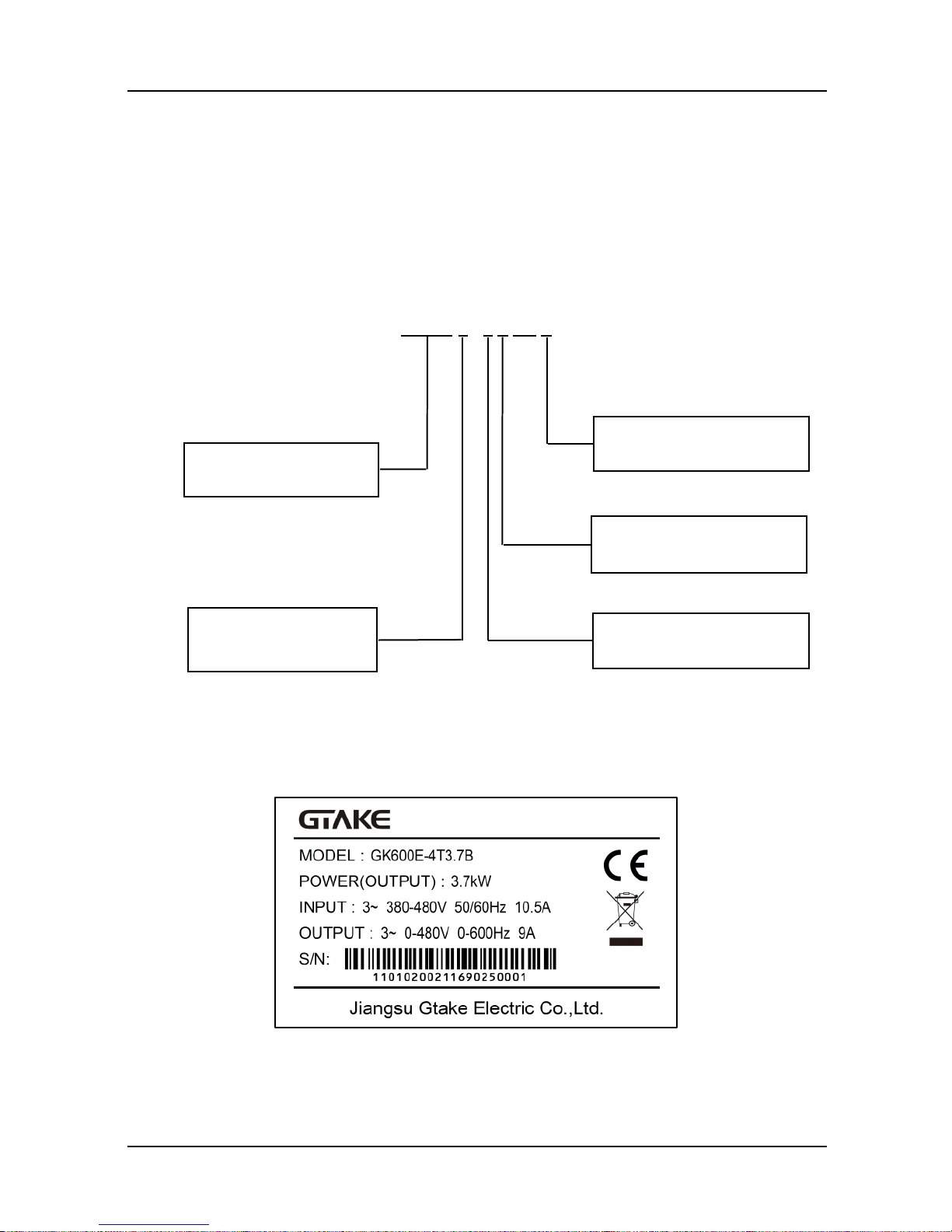
2.1 Model Explanation
Model shown on product nameplate indicates the series name, applicable type of power supply,
pow er class and the version of software and hardware, etc. via the combination of numbers,
symbols and letters.
GK600 E - 4 T 7.5 B
Fig. 2-1 Product model explanation
2.2 Nameplate Information
Fig. 2-2 Nameplate information
Dedicated drive
E:Elevator
4:Power 400 V AC
T:Power triphase
B: Brake chopper inbuilt
Product Platform
Chapter 2 Product Information GK600E User Manual
- 8 -
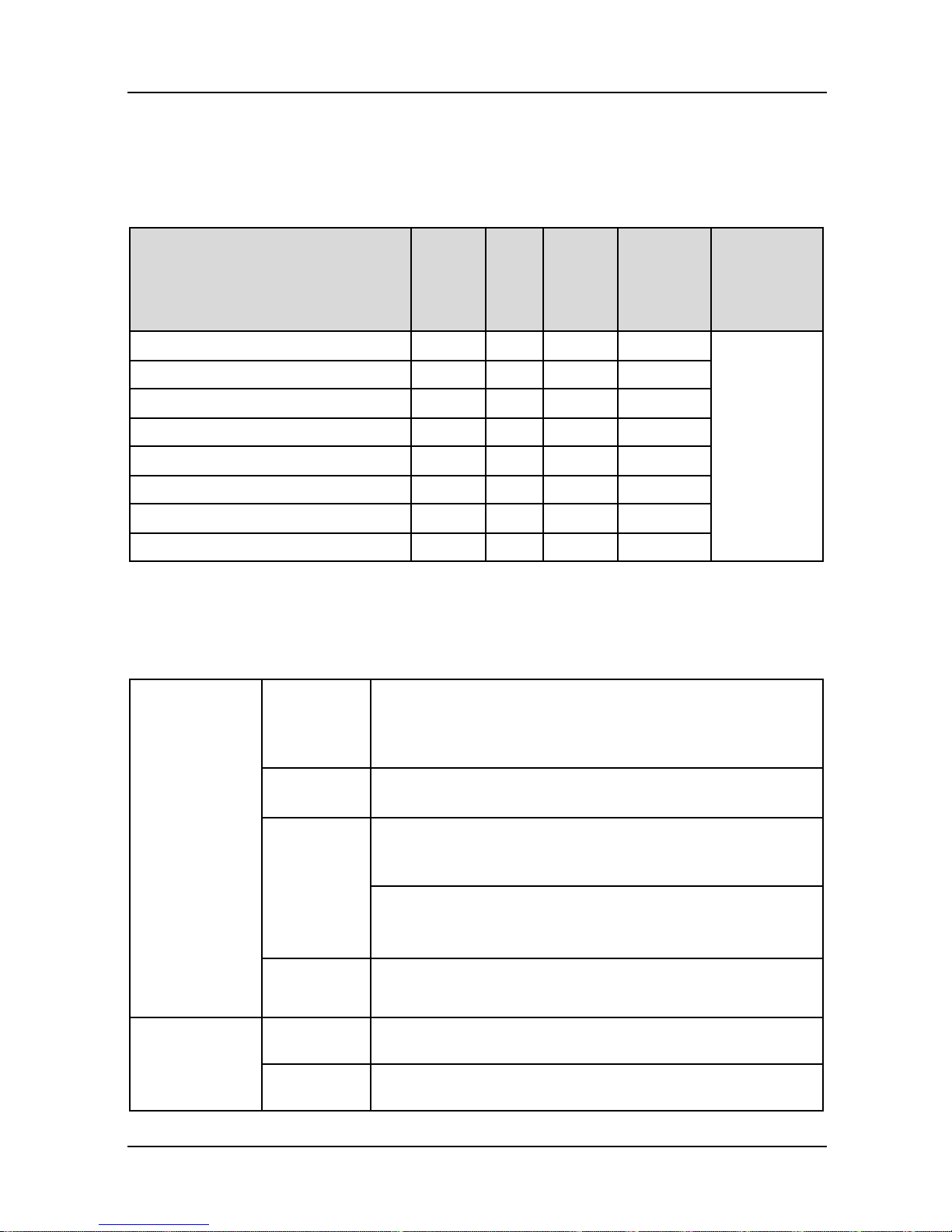
2.3 Information of Product Model
Table 2-1 Product model and technical data
■ GK600E-4T □□□, three-phase 400V input, heavy duty
Drive model
Pow er
rating
(kW)
Rated
output
current
(A)
Rated
input
current
(A)
Applicable
motor (kW)
Brake
chopper
GK600E-4T3.7B
3.7
9.0
10.5
3.7
Inbuilt
GK600E-4T5.5B
5.5
13
14.6
5.5
GK600E-4T7.5B
7.5
17
20.5
7.5
GK600E-4T11B
11
24
29
11
GK600E-4T15B
15
30
35
15
GK600E-4T18.5B
18.5
39
44
18.5
GK600E-4T22B
22
45
50
22
GK600E-4T30B
30
60
65
30
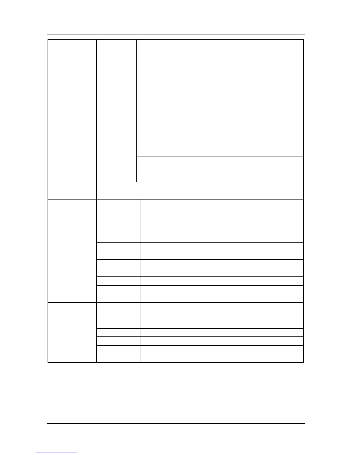
2.4 Technical Features of GK600E
Table 2-2 Technical Features of GK600E
Pow er input
Rated input
voltage
3-phase
AC380V/AC400V/
AC415V/AC440V/AC460V
Frequency
50Hz/60Hz, tolerance ±5%
Voltage
range
Continuous voltage fluctuation ±10%, short fluctuation
-15%~+10%, i.e. 400V: 323V~528V
(emergency input: UPS 220VAC, 1-phase)
Voltage out-of-balance rate <3%, distortion rate as per the
requirements of IEC61800-2
Rated input
current
See Section 2.3
Pow er output
Applicable
motor (kW)
See Section 2.3
Rated
current (A)
See Section 2.3

GK600E User Manual Chapter 2 Product Information
- 9 -
Output
voltage (V)
3-phase: 0~ rated input voltage, error < ±3%
Output
frequency
(Hz)
0.00~ 600.00Hz; unit: 0.01Hz
Overload
capacity
150% - 1min, 180% - 10s, 200% - 0.5s every 10 min
Control
characteristics
V/f patterns
V/f control
Range of
speed
regulation
1:100
Control
characteristics
Speed
accuracy
±0.5%
Start
torque
0.5Hz: 180%
Basic
functions
Start
frequency
0.00~ 600.00Hz
Accel/
Decel time
0.00~60000s
Switching
frequency
0.7kHz~16kHz
Frequency
setting
Digital setting + control panel ∧/∨
Digital setting + terminal UP/DOWN
Communication
Analog setting (AI1/AI2/EAI)
Terminal pulse setting
Motor
start-up
methods
Started from starting frequency
DC brake start-up
Flying start
Motor stop
methods
Ramp to stop
Coast to stop
Ramp stop + DC brake
Basic
functions
Dynamic
braking
capacity
Brake chopper working voltage: 650V-750V
Service time: 0-100.0s; brake chopper is inbuilt as default
for GK600E lift dedicated drives at GTAKE
DC brake
capacity
DC brake start frequency: 0.00~600.00Hz
DC brake current: 0.0~100.0%
DC brake time: 0.0~30.00s
Chapter 2 Product Information GK600E User Manual
- 10 -
Basic
functions
Input
terminals
7 digital inputs, one of which can be used for high-speed
pulse input, and compatible with active open collectors
NPN, PNP and dry contact input.
2 analog inputs, one of which is voltage/current
programmable, and the other supports voltage only.
Output
terminals
1 high-speed pulse output, 0~50kHz square wave signal
output. It can output signals such as frequency setting, or
output frequency, etc.
1 digital output
2 relay output
1 analog output, voltage/current output programmable; can
output signals such as frequency setting, or output
frequency, etc.
Protection
functions
Refer to Chapter 7- Troubleshooting
Environment
Place of
operation
Indoors, no direct sunlight, free from dust, corrosive
gases, flammable gases, oil mist, water vapor, water drop
or salt, etc.
Altitude
0-2000m . De-rate 1% for every 100m when the altitude is
above 1000 meters
Ambient
temperature
-10℃-40℃. The rated output current should be derated
1% for every 1℃ when the ambient is 40℃-50℃
Relative
humidity
0~95%, no condensation
Vibration
Less than 5.9m/s2 (0.6g)
Storage
temperature
-40℃~+70℃
Others
Efficiency at
rated Amps
Rated power
7.5kW and below : ≥93%
11~ 30kW: ≥ 95%
Installation
wall-mounted
IP grade
IP20
Cooling
method
Forced air cooling
GK600E User Manual Chapter 2 Product Information
- 11 -
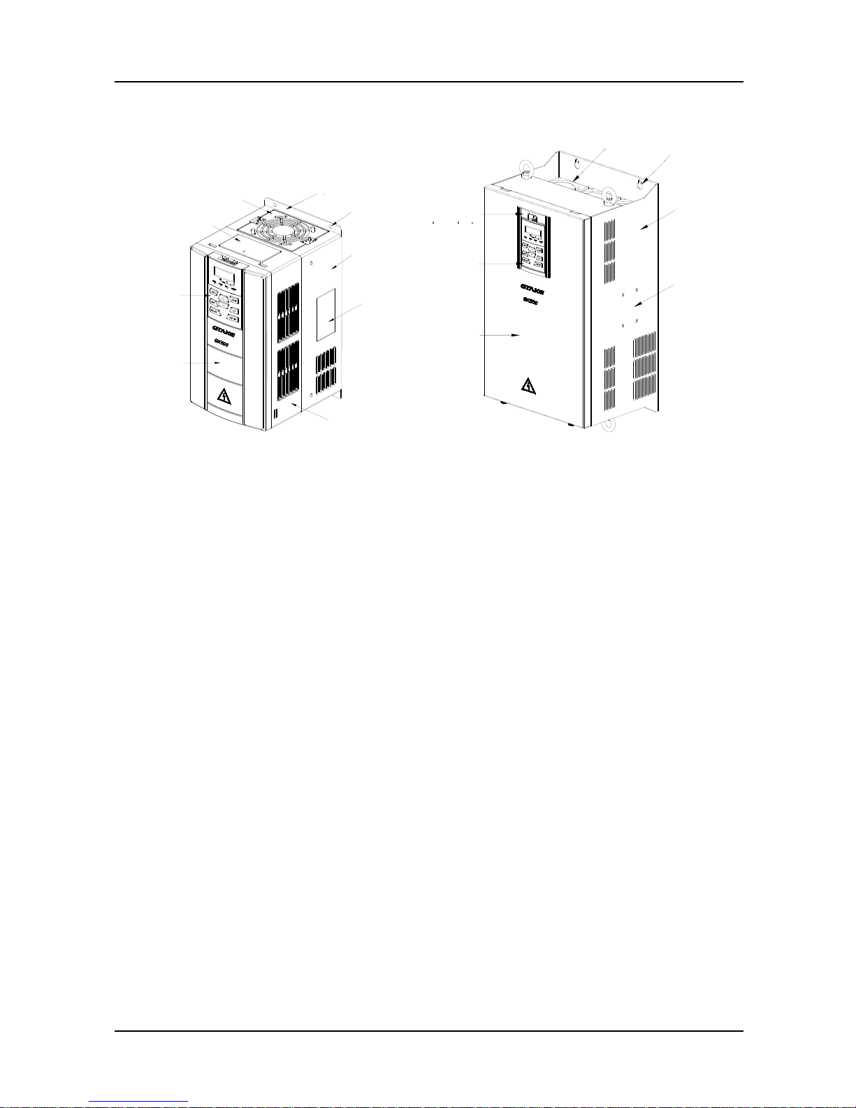
2.5 Parts Drawing
a) GK600E-4T15B and below b) GK600E-4T18.5B ~ GK600E-4T30B
Fig. 2-3 Parts drawing
铭牌
下壳体
安装孔
底板
风扇罩
防尘盖板
操作面板
盖板
中壳体
盖板
操作面板
安装孔
机箱
铭牌
风扇
托板
Fan cov er
Dust cover
Control
panel
Cov er
Control
panel
Cov er
Base plate
Mounting
holes
Mounting
holes
Lower
casing
Nameplate
Middle casing
Control
panel
Fans
Enclosure
Nameplate

Chapter 2 Product Information GK600E User Manual
- 12 -
2.6 Appearance, Mounting Dimensions and Weight
a) GK600E-4T3.7B ~ GK600E-4T15B
b) GK600E-4T18.5B ~ GK600E-4T30B
Fig. 2-4 External dimensions
GK600E User Manual Chapter 2 Product Information
- 13 -
Table 2-3 Appearance, mounting dimensions and weight
Model
External and installation dimensions (mm)
Weight
(kg)
W H D
W1
H1
H2
Mounting
hole dia.
GK600E-4T3.7B
120
245
169
80
233
220
5.5
2.9
GK600E-4T5.5B
145
280
179
105
268
255
5.5
3.9
GK600E-4T7.5B
GK600E-4T11B
190
365
187
120
353
335 6 6.2
GK600E-4T15B
GK600E-4T18.5B
270
475
220
170
460
435
8
15.5
GK600E-4T22B
GK600E-4T30B
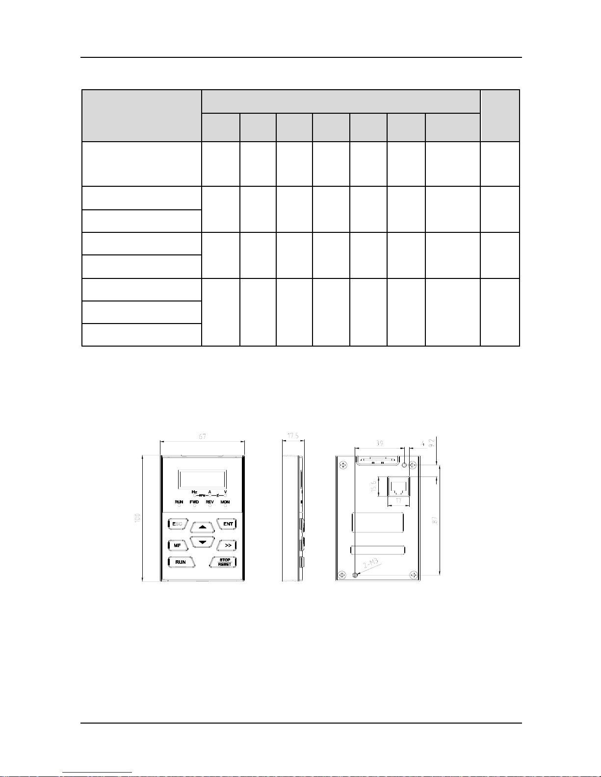
2.7 External Dimensions of Control Panel
Control panel model of GK600E series Elevator Dedicated Drives is KBU-BX1 whose
appearance and external dimensions are shown in Fig. 2-5.
Fig. 2-5 External dimensions of KBU-BX1
2.8 External Dimensions of Control Panel Bracket
A bracket should be provided to support the panel and a hole in the cabinet needs to be opened
when the control panel KBU-BX1 needs to be remotely used. Bracket model is KBU-DZ1
whose external dimensions are shown in Fig. 2-6 a). Fig. 2-6 b) shows applicable hole
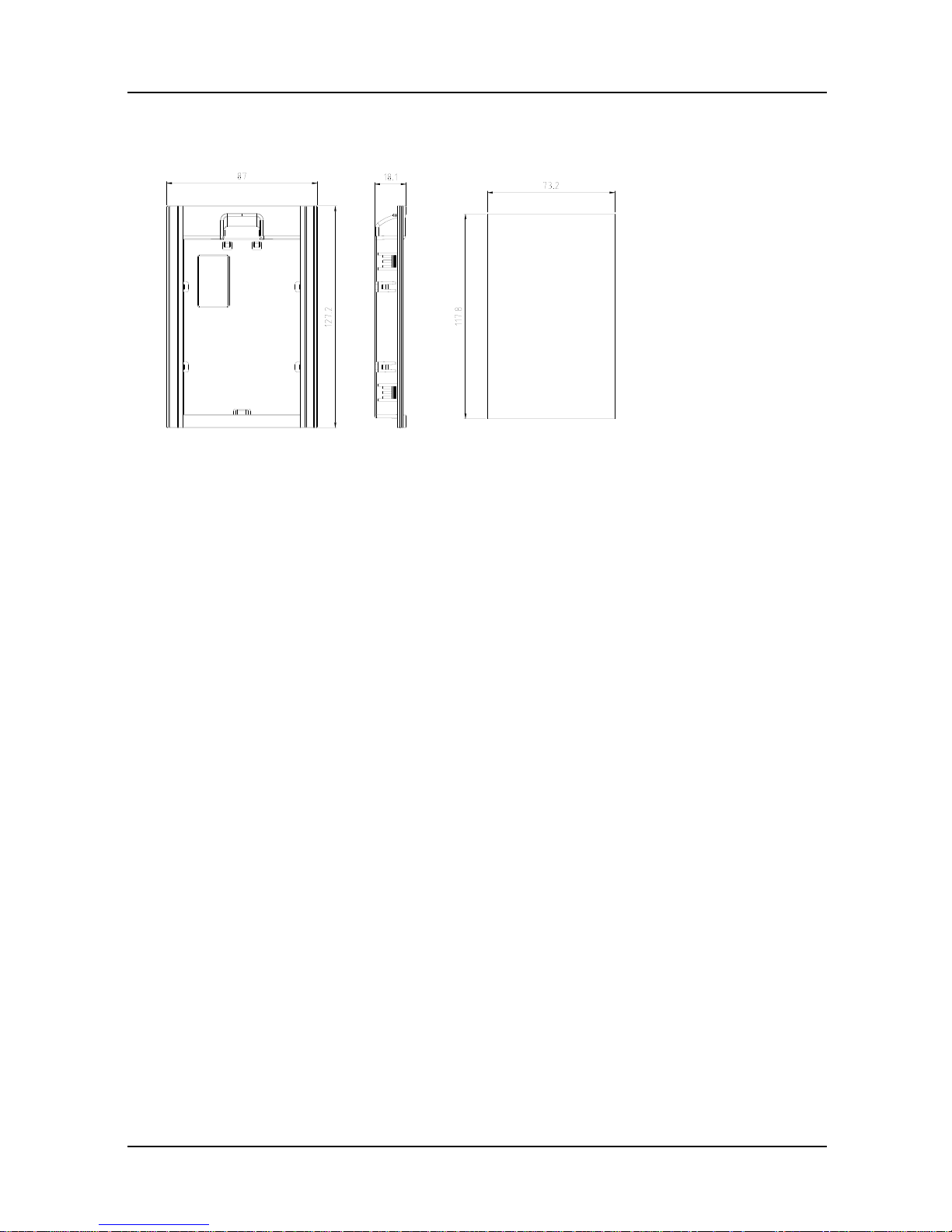
Chapter 2 Product Information GK600E User Manual
- 14 -
dimensions in the cabinet.
a) External dimensions of KBU-DZ1 b) Hole dimensions in the cabinet
Fig. 2-6 External dimensions of KBU-DZ1 and cabinet hole dimensions
Panel TH Hole WTH
1.2mm 73.2mm
1.5mm 74.4mm
2mm 75.5mm
GK600E User Manual Chapter 3 Installation and Wiring
- 15 -
Chapter 3 Installation and Wiring
3.1 Installation Environment
1) Ambient temperature is in the range of -10℃~ 40℃.
2) Drive should be installed on surface of flame retardant object, with adequate surrounding
space for heat dissipation.
3) Installation should be performed w here vibration is less than 5.9m/s2 (0.6g).
4) Protect from moisture and direct sunlight.
5) Protect the cooling fan by avoiding oil, dust and metal particles.
6) Do not expose to an atmosphere with flammable gases, corrosive gases, explosive gases
or other harmful gases.
7) Prevent drilling residues, wire ends and screws falling into drive.
8) Ventilation part of the drive should be installed outside from harsh environment (e.g. textile
facilities with fiber particles and chemical facilities filled with corrosive gases.
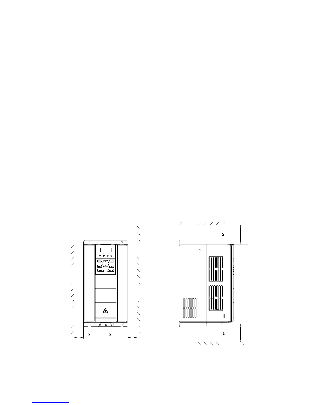
3.2 Minimum Mounting Clearances
To ensure favorable heat dissipation, mount the drive upright on a flat, vertical and level surface
as per Fig. 3.1. For installation inside cabinet, the product shall be mounted side by side to the
greatest extent while adequate surrounding space shall be preserved for favorable heat
dissipation.
Fig. 3-1 Minimum mounting clearances of GK600E-4T15B and below
空气流通位置
100mm
100mm
空气流通位置
30mm
30mm
Vent clearance
Vent clearance
Chapter 3 Installation and Wiring GK600E User Manual
- 16 -
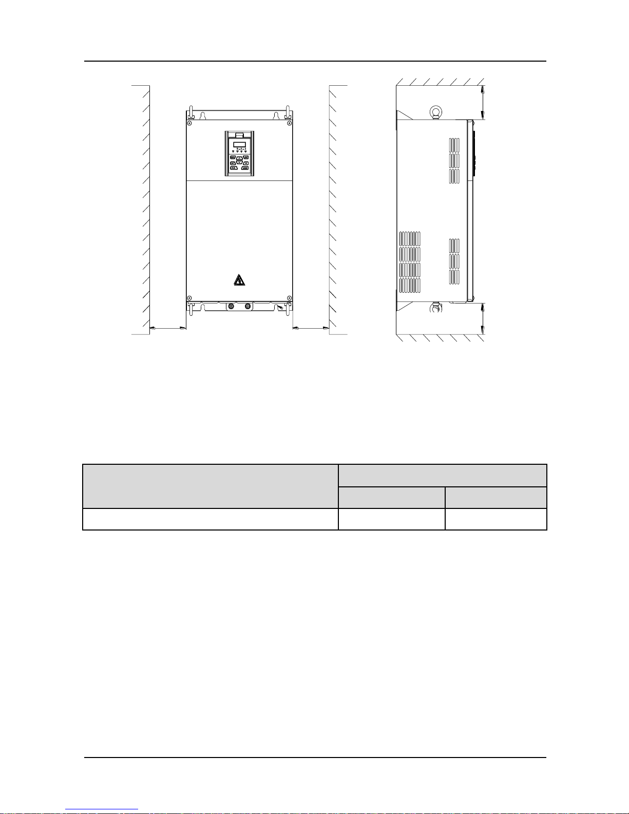
Fig. 3-2 Minimum mounting clearances of GK600E-4T18.5B and above
ATTENTION:
When mounting a drive GK600E-4T18.5B or above, the minimum mounting clearances as
set forth in Table 3-1 should be assured.
Table 3-1 Requirement of minimum mounting clearances
Drive model
Mounting clearances (mm)
A
B
GK600E-4T18.5B ~ GK600E-4T30B
≥50
≥200
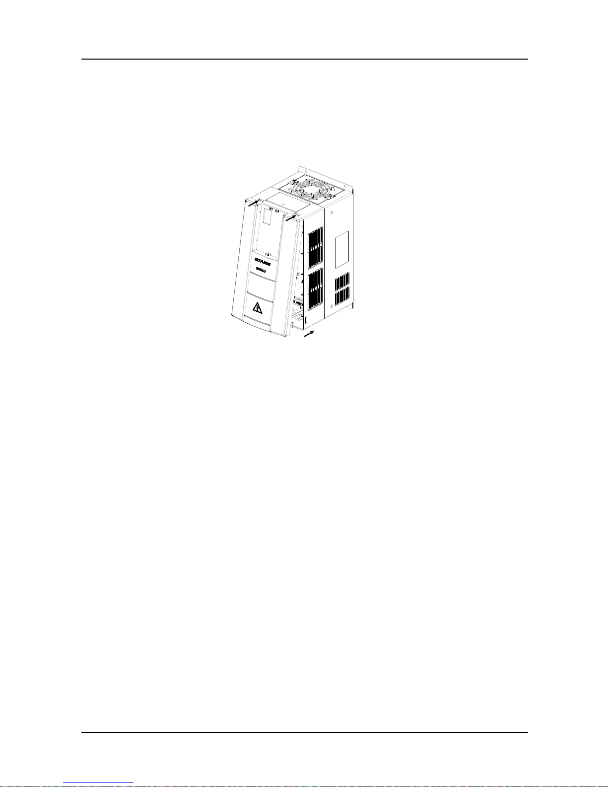
3.3 Remove & Mount Control Panel and Cover
3.3.1 Remove and Mount Control Panel
Remove control panel
Press the buckle of control panel as indicated by number "1" in Fig. 3-3, then pull the panel
out to release as indicated by "2".
Mount control panel
Slightly slant the panel in the direction as indicated by number "1" in Fig. 3-4 and align it to
clamping port at lower part of panel bracket, then press it in as indicated by "2". When a
"click" sound heard, it indicates clamping has been properly made.
空气流通位置
B
空气流通位置
B
A A
Vent clearance
Vent clearance

GK600E User Manual Chapter 3 Installation and Wiring
- 17 -
Fig. 3-3 Remove the control panel Fig. 3-4 Mount the control panel
3.3.2 Open & Mount the Covers of GK600E-4T3.7B ~ GK600E-4T15B
Remove the control panel
Use the remove method as stated in Section 3.3.1.
Open the cover
Method 1: loosen the captive cover screws as shown in Fig. 3-5 a) (provided only for
11/15kW model), hold the left and front sides of middle housing with left hand, put the right
thumb into the buckle and press tightly on cover with the other four fingers, pull the lower
part of the cover out to release, as indicated by number "2".
Method 2: loosen the captive cover screws, as indicated by number "1" in Fig. 3-5 b)
(provided only for 11/15kW model), use a sizeable slotted screwdriver to push the buckle
slightly at the low er part of the cover to make buckle naturally off the groove, as indicated
by "2", pull the cover out to release, as indicated by number "3".
a) Method 1 b) Method 2
Fig. 3-5 Open the cover
1
2
1
2
1
1
螺丝刀
Screwdriver
Chapter 3 Installation and Wiring GK600E User Manual
- 18 -
Mount the cover
On the completion of w iring, insert the buckle at higher part of the cover into the grooves at
middle housing as indicated by number "1" in Fig. 3-6, then push in the lower part of the
cover as indicated by "2". When a "click" sound heard, it indicates clamping has been
properly made. Tighten the screws (provided only for 11/15kW model) in buckle grooves
as finish.
Fig. 3-6 Mount the cover
Mount the control panel
Use the mounting method as stated in Section 3.3.1.
ATTENTION:
Be sure to remove the control panel before opening the cover and mount the cover before
mounting the control panel.
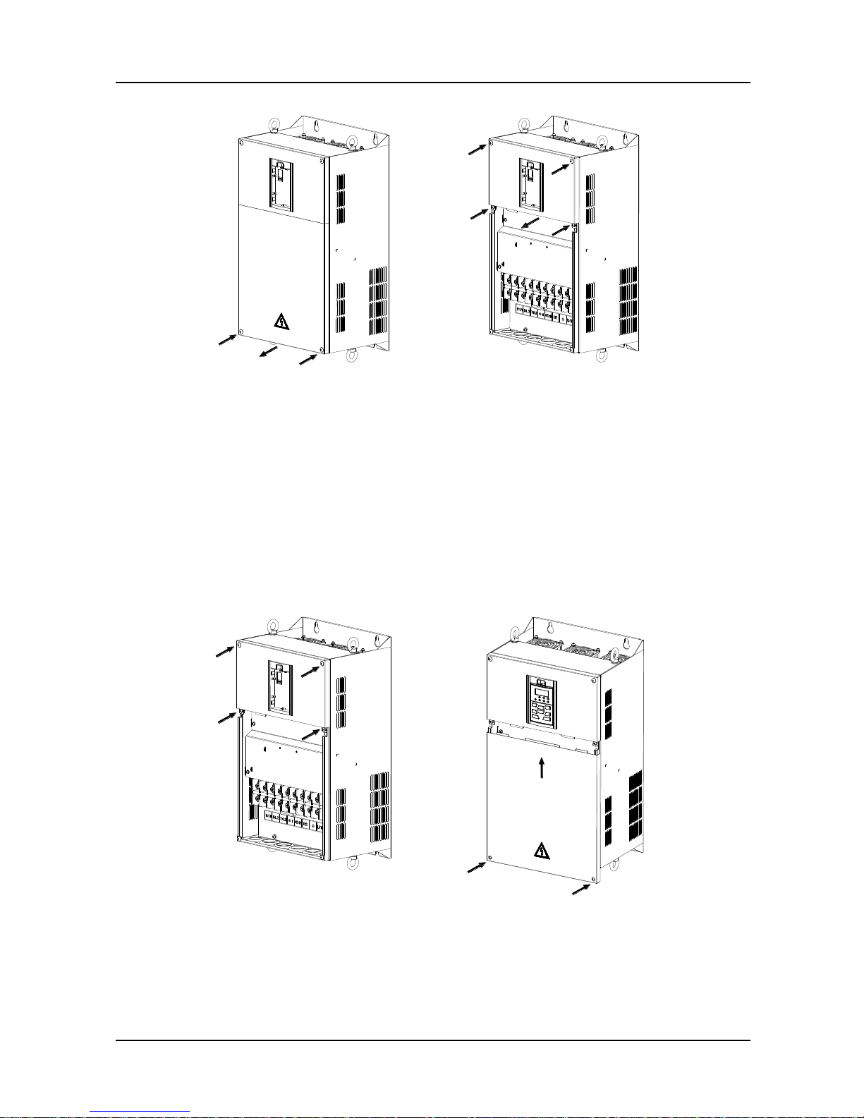
3.3.3 Open & Mount the Covers of GK600E-4T18.5B and above
Remove the control panel
Use the remove method as stated in Section 3.3.1.
Open the lower cover
Loosen the two captive cover screws at lower part of the lower cover by using cross
screwdriver, as indicated by number "1" as shown in Fig. 3-7, then pull the cover out and
up as indicated by number "2".
Open the upper cover
Loosen the two captive cover screws at lower part of the lower cover by using cross
screwdriver, as indicated by number "3" and “4” as shown in Fig. 3-7, then pull the cover
out and up as indicated by number "5".
1
1
2
GK600E User Manual Chapter 3 Installation and Wiring
- 19 -
Fig. 3-7 Open & mount the covers
Mount the upper cover
Insert the upper part of the cover into mounting groove as shown in Fig. 3-8 (left), close the
upper cover, use cross screwdriver to tighten the four captive screws, as indicated by
number “1” and "2".
Mount the lower cover
Insert the lower cover into upper cover in the direction as indicated by number 3 in Fig. 3-8
(right), close the lower cover and tighten the two captive screws, as indicated by number
"4".
Fig. 3-8 Mount the upper and lower covers
Mount the control panel
Use the mounting method as stated in Section 3.3.1.
1
1
2
3
4
4
5
3
1
2
2
1
3
4
4

Chapter 3 Installation and Wiring GK600E User Manual
- 20 -
ATTENTION:
Be sure to remove the control panel before opening the cover and mount the cover before
mounting the control panel.
GK600E User Manual Chapter 3 Installation and Wiring
- 21 -
3.4 Configuration of Peripheral Devices
3.4.1 Standard Configuration of Peripheral Devices
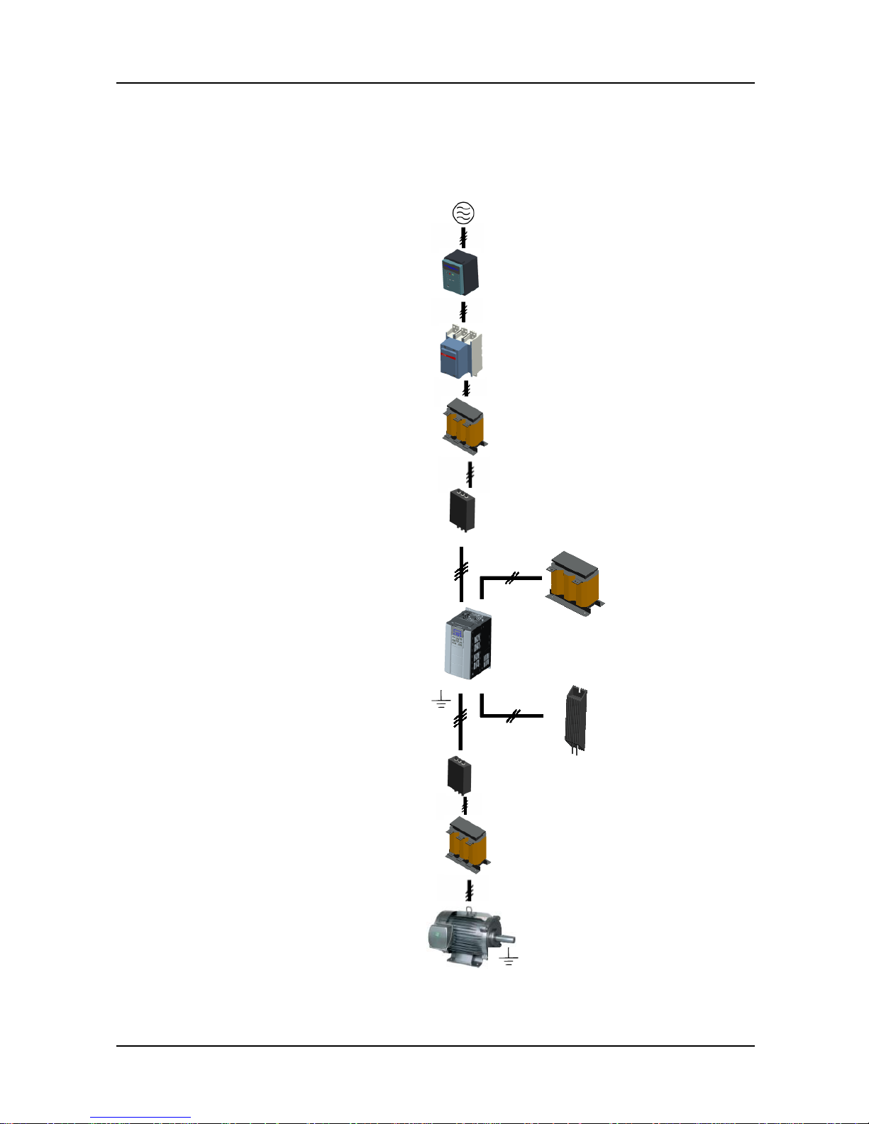
Fig. 3-9 Standard configuration of peripheral devices
Output AC Reactor
Braking Resistor
Pow er Supply
Circuit Breaker or RCD
Contactor
Input AC Reactor
DC Choke
Output Filter
AC Motor Drive
PE
Motor
PE
Input Filter

Chapter 3 Installation and Wiring GK600E User Manual
- 22 -
3.4.2 Instructions for Peripheral Devices
Table 3-2 Instructions for peripheral devices
Name
Instructions
Pow er
supply
Input three-phase AC pow er supply should be in the range as specified in
this manual
Circuit
breaker
Purpose: disconnect power supply and protect the equipments in case of
abnormal overcurrent occurs
Type selection: breaking current of circuit breaker is defined to be 1.5~2
times the rated current of the drive
Breaking time characteristic of circuit breaker should be selected based on
overload protection time characteristic of the drive
RCD
Purpose: since the drive outputs PWM HF chopping voltage, HF leakage
current is inevitable
Type selection: type B dedicated RCD is recommended
Contactor
For safety's sake, do not frequently close and break the contactor since this
may bring about equipment faults
Do not control the start & stop of the drive directly through switch on and off
the contactor since this w ill result in a reduction on the product life
Input AC
reactor or
DC choke
Improve power factor
Reduce the impact of imbalanced three-phase input AC power supply on
the system
Suppress higher harmonics and reduce the conducted and radiated
interference to peripheral devices
Restrict the impact of impulse current on rectifier bridges
Input filter
Reduce conducted interference from power supply to the drive, improve the
immunity of the drive from noise
Reduce conducted and radiated interference of the drive to peripheral
devices
Brake unit
and
braking
resistor
Purpose: consume motor feedback energy to attain quick brake
Type selection: Contact GTAKE technical personnel for type selection of
brake unit. Refer to type selection of braking resistor in Table 3-3 Type
Selection of Peripheral Devices.
Output filter
Reduce conducted and radiated interference of the drive to peripheral
devices
Output AC
reactor
Avoid the motor insulation damage result from harmonic voltage
Reduce frequent protection from the drive caused by leakage current
In case the cable connecting drive and motor is over 100 meters, output AC
reactor recommended
Motor
Should match the drive
GK600E User Manual Chapter 3 Installation and Wiring
- 23 -
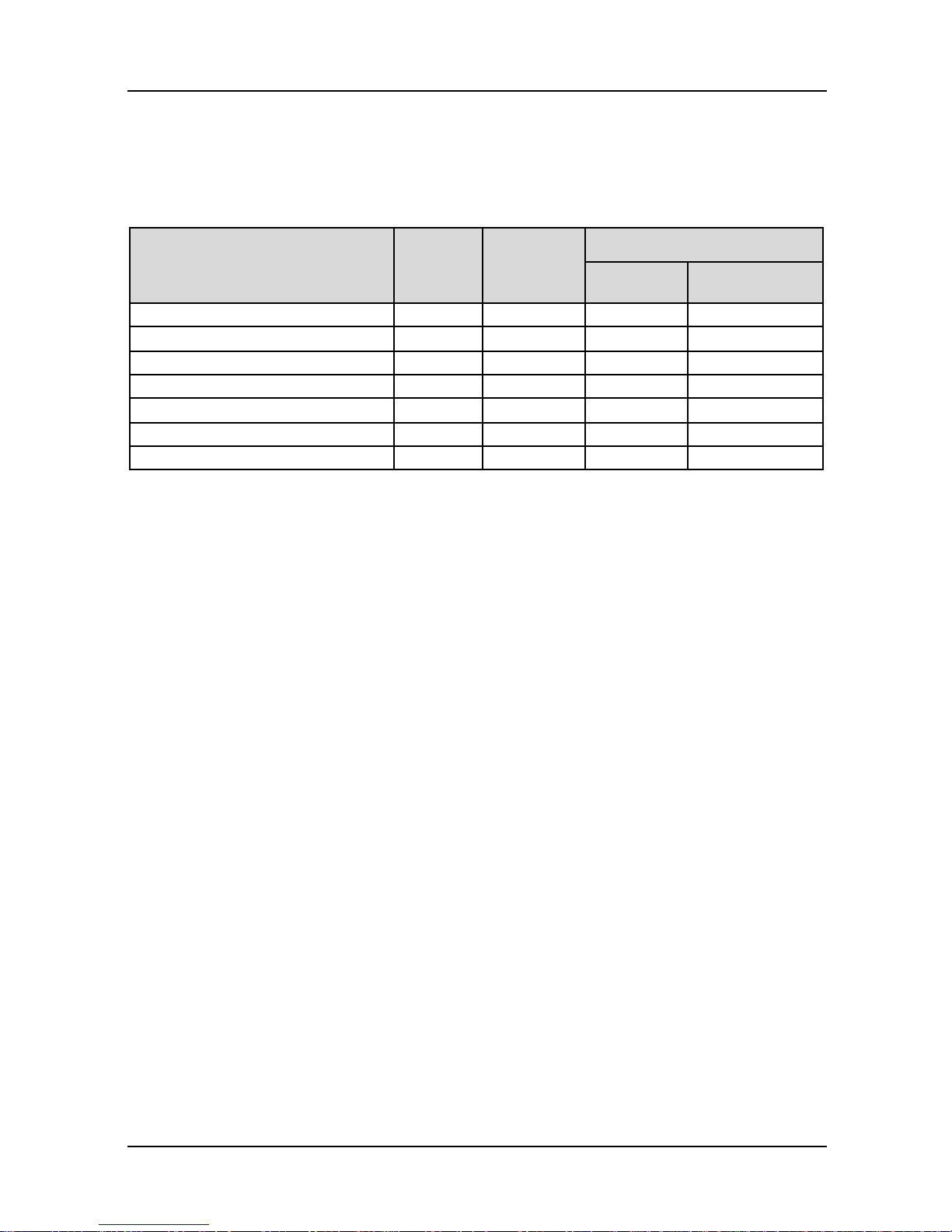
3.4.3 Selection of Peripheral Devices
Table 3-3 Selection of peripheral devices
■GK600E-4T B, Three phase 400V input
Drive model
Circuit
breaker
(A)
Contactor(A)
Brake resistor /Brake chopper*
Pow er (W)
Resistance (Ω)
GK600E-4T3.7B
16
12
450
≥75
GK600E-4T5.5B
20
18
500
≥75
GK600E-4T7.5B
32
25
500
≥75
GK600E-4T11B
40
32
800
≥30
GK600E-4T18.5B
63
50
1300
≥16
GK600E-4T22B
63
50
1500
≥16
GK600E-4T30B
100
65
2000
≥16
* On the premise of fulfilling brake requirement, brake resistance value might be bigger than the minimum value as
stated in the table. Failure to comply may result in damage to the resistor and the drive. Brake resistors are not
built in and need to be sourced additionally.
Chapter 3 Installation and Wiring GK600E User Manual
- 24 -
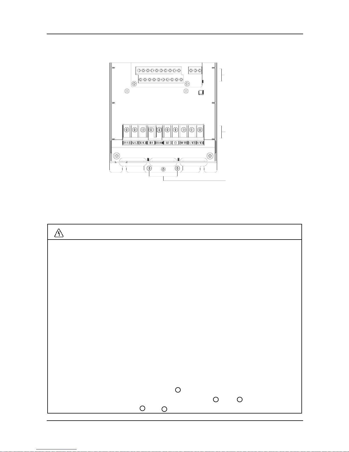
3.5 Terminal Configuration
Fig. 3-10 Terminal configuration
3.6 Main Circuit Terminals and Wiring
WARNING
Only qualified personnel familiar w ith AC motor drives and passenger lift are allowed to
implement wiring. Failure to comply may result in equipment damage and/or personnel
injury even death.
Wiring should be in strict accordance with this manual, otherwise hazard of electric
shock or equipment damage exists.
Make sure input power supply has been completely disconnected before wiring
operation. Failure to comply will result in personnel injury even death.
All w iring operations and lines should comply with EMC and national and local industrial
safety regulations and/or electrical codes. The conductor diameter should be in
accordance with recommendations of this manual. Otherwise, hazard of equipment
damage, fire, and/or personnel injury exists.
Since leakage current of the drive may exceed 3.5mA, for safety's sake, the drive and
the motor must be grounded so as to avoid hazard of electric shock.
Be sure to perform w iring in strict accordance with the drive terminal marks. Never
connect three-phase power supply to output terminals U/T1, V/T2 and W/T3. Failure to
comply will result in equipment damage.
Only mount braking resistors at terminals and B2.
When needed, only mount DC reactors at terminals and , and remove the
jumper connected between and . Never connect the jumper and DC reactor to
控制回路端子
主回路端子
接地端子
Control circuit terminals
Main circuit terminals
+ 2/B1
+ 1
+ 2
+ 1
+ 2
Grounding terminals
GK600E User Manual Chapter 3 Installation and Wiring
- 25 -
other terminals since this will result in short circuit and equipment damage.
Wiring screws and bolts for main circuit terminals must be screwed tightly. Failure to
comply may result in faults and/or equipment damage.
ATTENTION
Signal wires should be away from main power lines to the best of possibility. In the
event that this cannot be ensured, vertical cross arrangement should be adopted,
reducing EMI interference to the signal wires as much as possible.
In case the motor cable exceeds 100m, an appropriate output reactor should be
mounted.
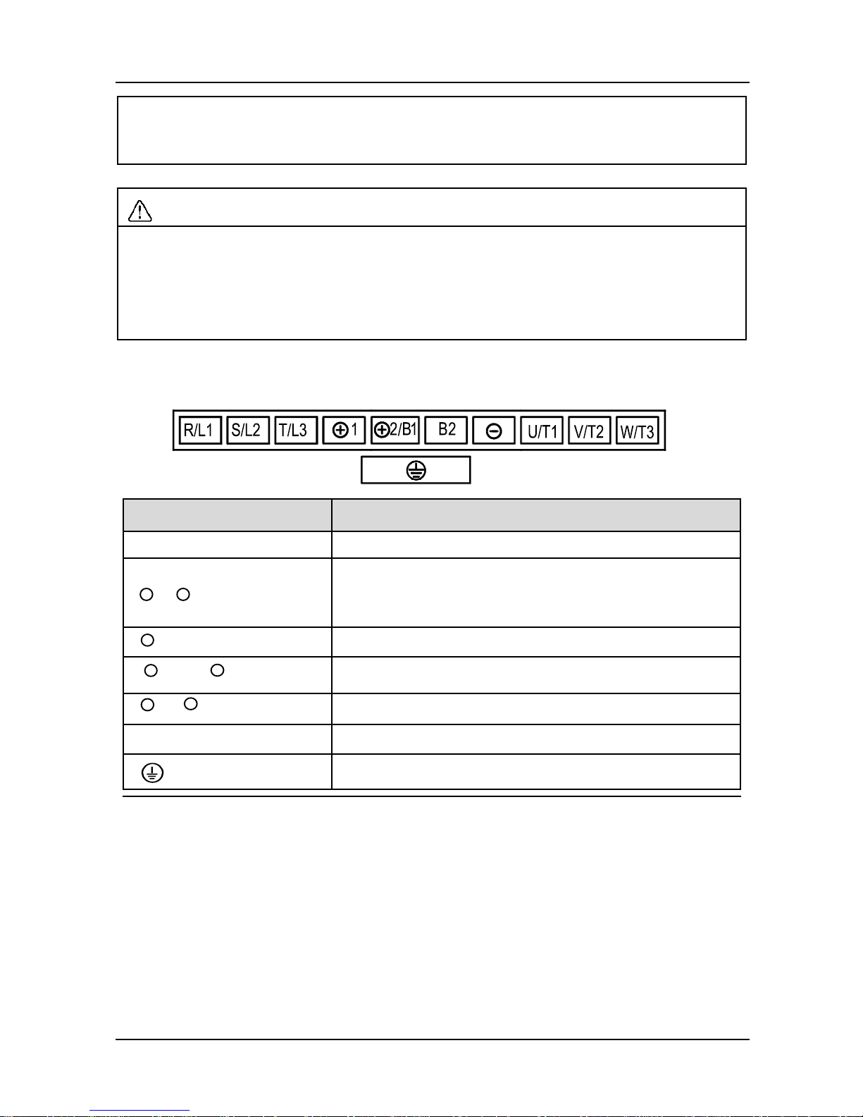
3.6.1 Main Circuit Terminals of GK600E-4T3.7B ~ GK600E-4T30B
Terminal marks
Designation and function of terminals
R/L1, S/L2, T/L3
Three-phase AC input terminals
,
DC reactor connection terminals. Connected w ith a
jumper as factory default
, B2
Built-in brake unit connection terminals*
,
DC input terminals of externally mounted brake unit
,
DC power supply input terminals
U/T1, V/T2, W/T3
Three-phase AC output terminals
Ground terminal PE
-
+ 1
+ 2/B1
+ 2/B1
+ 2/B1
-
+ 1
 Loading...