

GTAKE GK600E-4T5.5B, GK600E-4T3.7B, GK600E-4T18.5B, GK600E-4T22B, GK600E-4T30B User Manual
...

Preface
Thank you for choosing GTAKE GK600E Series Elevator Dedicated Drives. This user
manual presents a detailed description of GK600E series with respect to product features,
structural characteristics, functions, installation, parameter setting, troubleshooting,
commissioning and daily maintenance, etc. Be sure to carefully read through the safety
precautions before use, and use this product on the premise that personnel and equipment
safety is ensured.
IMPORTANT NOTES
Please assure the intactness of product enclosure and all safety covers before installation.
Operation must conform to the requirements of this manual and local industrial safety
regulations and/or electrical codes.
Contents of this manual may be subject to appropriate modification as a result of product
upgrade, specification change and update of the manual.
In the event of damage or loss of user manual, users may ask local distributors, offices or
our Technical Service Department for a new one.
If any item as stated in this manual is not clear enough, please contact our Technical
Service Department.
If any anomaly occurs after power up or during the operation, it is essential to stop the
machine and identify the fault or seek technical services as soon as possible.
Telephone number of our Technical Service Department: (+86) 0755-86392601.

Table of Contents
Chapter 1 Safety Precautions ............................................................................................- 1 -
1.1 Safety Considerations ........................................................................................- 1 -
1.2 Other Considerations .........................................................................................- 5 -
Chapter 2 Product Information ..........................................................................................- 7 -
2.1 Model Explanation..............................................................................................- 7 -
2.2 Nameplate Information .......................................................................................- 7 -
2.3 Information of Product Model .............................................................................- 8 -
2.4 Technical Features of GK600E...........................................................................- 8 -
2.5 Parts Drawing...................................................................................................- 11 -
2.6 Appearance, Mounting Dimensions and Weight...............................................- 12 -
2.7 External Dimensions of Control Panel ..............................................................- 13 -
2.8 External Dimensions of Control Panel Bracket.................................................- 13 -
Chapter 3 Installation and Wiring ....................................................................................- 15 -
3.1 Installation Environment ...................................................................................- 15 -
3.3 Remove & Mount Control Panel and Cover......................................................- 16 -
3.4 Configuration of Peripheral Devices .................................................................- 21 -
3.5 Terminal Configuration .....................................................................................- 24 -
3.6 Main Circuit Terminals and Wiring ....................................................................- 24 -
3.7 Control Terminal Wiring ....................................................................................- 26 -

3.8 Control Terminal Specification ..........................................................................- 30 -
3.9 Control Terminal Usage ....................................................................................- 31 -
3.10 Instruction of Signal Sw itches...........................................................................- 37 -
3.11 EMI Solutions ...................................................................................................- 37 -
Chapter 4 Operation and Run Instructions .....................................................................- 40 -
4.1 Operation of Control Panel ...............................................................................- 40 -
Chapter 5 Elevator Dedicated Parameters ......................................................................- 55 -
5.1 Standard Wiring ...............................................................................................- 55 -
5.2 Elevator Sequence ...........................................................................................- 56 -
5.3 Startup Manual .................................................................................................- 57 -
Chapter 6 List of Parameters ...........................................................................................- 75 -
Chapter 7 Troubleshooting ............................................................................................- 108 -
7.1 Fault Causes and Troubleshooting.................................................................- 108 -
Chapter 8 Maintenance................................................................................................... - 117 -
8.1 Routine Inspection.......................................................................................... - 117 -
8.2 Regular Maintenance ..................................................................................... - 118 -
8.3 Replacement of Vulnerable Parts ................................................................... - 119 -
8.4 Storage...........................................................................................................- 120 -

GK600E User Manual Chapter 1 Safety Precautions
- 1 -
Chapter 1 Safety Precautions
Safety Precautions
Safety signs in this manual:
WARNING: indicates the situation in which the failure to follow operating requirements
may result in fire or serious personal injury or even death.
ATTENTION: indicates the situation in which the failure to follow operating requirements
may cause moderate or slight injury and damage to equipment.
Users are requested to read this chapter carefully when installing, commissioning and repairing
this product and perform the operation according to safety precautions as set forth in this
chapter without violation. GTAKE bears no responsibility for any injury and loss as a result of
any violation.
1.1 Safety Considerations
1.1.1 Prior to Installation
WARNING
Do not touch control terminals, circuit boards and any other electronic parts and
components with bare hands.
Do not use the drive whose component(s) is/are missing or damaged. Failure to comply
may result in more faults and/or personal injury even death.
ATTENTION
Check if the product information indicated on the nameplate is consistent w ith the order
requirements. If not, do not install it.
Do not install the drive in the event that the packing list does not match the real
equipment.
1.1.2 Installation
WARNING
Only qualified personnel familiar with adjustable frequency AC drives and passenger lift
should plan or implement the installation. Failure to comply may result in equipment damage
and/or personnel injury even death.
Chapter 1 Safety Precautions GK600E User Manual
- 2 -
This equipment must be mounted on metal or other flame retardant objects. Failure to
comply may result in fire.
This equipment must be mounted in an area which is away from combustibles and heat
sources. Failure to comply may result in fire.
This equipment must in no case be mounted in the environment exposed to explosive gases.
Failure to comply may result in explosion.
Never adjust mounting bolts of this equipment, especially the ones with red marks. Failure to
comply may result in equipment damage.
ATTENTION
Handle the equipment gently and take hold of its sole plate so as to avoid foot injury or
equipment damage.
Mount the equipment where its weight can be w ithstood. Failure to comply may result in
equipment damage and/or personnel injury if falling happens.
Make sure the installation environment conforms to the requirements as stated in
Section 2.4. If not, de-rating is necessary. Failure to comply may result in equipment
damage.
Prevent drilling residues, wire ends and screws from falling into the equipment during
installation. Failure to comply may result in faults or equipment damage.
When mounted in a cabinet, this equipment should be provided with appropriate heat
dissipation. Failure to comply may result in faults or equipment damage.
1.1.3 Wiring
WARNING
Only qualified personnel familiar with adjustable frequency AC drives and passenger lift
should plan or implement the wiring. Failure to comply may result in personnel injury and/or
equipment damage.
Wiring must strictly conform to this manual. Failure to comply may result in personnel
injury and/or equipment damage.
Make sure the input power supply has been completely disconnected before wiring.
Failure to comply may result in personnel injury and/or equipment damage.
All w iring operations must comply with EMC and safety regulations and/or electrical
codes, and the conductor diameter should conform to recommendations of this manual.
Failure to comply may result in personnel injury and/or equipment damage.
Since overall leakage current of this equipment may be bigger than 3.5mA, for safety's
sake, this equipment and its associated motor must be well grounded so as to avoid risk
of electric shock.
Be sure to implement w iring in strict accordance w ith the marks on this equipment’s
GK600E User Manual Chapter 1 Safety Precautions
- 3 -
terminals. Never connect three-phase power supply to output terminals U/T1, V/T2 and
W/T3. Failure to comply may result in equipment damage.
Install braking resistors at terminals and B2 only. Failure to comply may result in
equipment damage.
Install DC reactor at terminals and , and remove the jumper connected at
and . Never connect this jumper and DC reactor to any other terminals. Failure to
comply may result in short circuit and equipment damage.
Wiring screws and bolts for main circuit terminals must be screwed tightly. Failure to
comply may result in equipment damage.
AC 220V signal is prohibited from connecting to other terminals than control terminals
RA, RB and RC. Failure to comply may result in equipment damage.
ATTENTION
Since all adjustable frequency AC drives from GTAKE have been subjected to hi-pot
test before delivery, users are prohibited from implementing such a test on this
equipment. Failure to comply may result in equipment damage.
Signal wires should be away from main power lines to the best of the possibility. If this
cannot be ensured, vertical cross-arrangement shall be implemented, otherwise
interference noise to control signal may occur.
If motor cables are longer than 100m, it is recommended output AC reactor be used.
Failure to comply may result in faults.
1.1.4 Run
WARNING
Drives which have been stored for more than 2 years should be used with voltage
regulator to gradually boost the voltage when applying power to the drives. Failure to
comply may result in equipment damage.
Be sure to implement the wiring as per Section 3.4 before applying power to the drive.
Failure to comply may result in equipment damage and/or electric shock hazard.
Be sure to confirm the completion and correctness of the drive wiring and close the
cover before applying power to the drive. Do not open the cover after applying power.
Failure to comply may result in electric shock hazard.
After applying the power, never touch the drive and peripheral circuits no matter what
state the drive is under, otherwise there will be electric shock hazard.
Prior to running the drive, make sure there is no person in surrounding area who can
reach the motor so as to prevent personal injury.
When the drive is running, foreign bodies should be prevented falling into the
equipment. Failure to comply may result in faults and/or equipment damage.
+ 2/B1
+ 1
+ 2
+ 1
+ 2
Chapter 1 Safety Precautions GK600E User Manual
- 4 -
Only qualified technicians familiar with adjustable frequency AC drives are allowed to
perform signal test during operation. Failure to comply may result in equipment damage
and/or personal injury.
Never change the drive parameters at will. Failure to comply may result in equipment
damage.
ATTENTION
Make sure the number of phases of power supply and rated voltage are consistent w ith
product nameplate. If not, contact the seller or GTAKE.
Check there are no short circuits in peripheral circuits connected with the drive, and
make sure the connection is tight. Failure to comply may result in equipment damage.
Make sure the motor and associated machinery are within allowable range of service
prior to operation. Failure to comply may result in equipment damage.
Never touch fans, heat sink and braking resistor with bare hands. Failure to comply may
result in equipment damage and/or personal injury.
It is not allowed to start & stop the drive frequently via direct switching power on or off.
Failure to comply may result in equipment damage.
Make sure the drive is in a non-output status before switch-on/sw itch-off of the drive
output and/or contactor. Failure to comply may result in equipment damage.
1.1.5 Maintenance
WARNING
Only qualified technicians are allowed to implement the maintenance, and
troubleshooting.
Never implement the maintenance, and troubleshooting before power supply has been
turned off and discharged completely. Failure to comply may result in equipment
damage and/or personal injury.
To avoid an electric shock hazard, wait at least 10 minutes after the power has been
turned off and make sure the residual voltage of the bus capacitors has discharged to
0V before performing any work on the drive.
After the replacement of the drive, be sure to perform the same procedures in strict
accordance with the above-noted rules.
GK600E User Manual Chapter 1 Safety Precautions
- 5 -
ATTENTION
Do not touch the electric components with bare hands during maintenance, and
troubleshooting. Failure to comply may result in component damage due to ESD.
All pluggable components can be inserted or pulled out only when power has been
turned off.
1.2 Other Considerations
1.2.1 Input Power Supply
This series of drives are not applicable to applications out the range of operating voltage as set
forth in this manual. If necessary, please use booster to rise or drop the voltage to regulated
voltage range.
1.2.2 Surge Protection
This series of drives are furnished with surge suppressor that has certain resistance to lightning
induction. However, users in areas where lightning occurs frequently need to mount an external
surge suppressor in front of power input side of the drive.
1.2.3 Operation of Contactor
As to the configuration of peripheral devices recommended by this manual, it is necessary to
mount a contactor between the power supply and input side of the drive. Such a contactor
should not be used as a control device to start and stop the drive, as frequent charging &
discharging shall reduce the service life of internal electrolytic capacitors.
When it is necessary to mount a contactor between the drive output and the motor, it should be
ensured the drive is in a non-output status before switch-on/switch-off of such a contactor.
Failure to comply may result in damage to the drive.
1.2.4 Output Filter
Since the drive output is PWM high frequency chopping voltage, mounting filter devices such
as an output filter and an output AC reactor between the motor and the drive shall effectively
reduce output noise, avoiding interference to other surrounding equipment.
Be sure not to mount phase-shifting capacitor or surge absorber at output side of the drive
since this may cause damage to the drive as a result of over-temperature.

Chapter 1 Safety Precautions GK600E User Manual
- 6 -
1.2.5 Insulation of the Motor
In view of the fact that the drive output is PWM high frequency chopping voltage accompanied
by higher harmonics, the noise, temperature rise and vibration of the motor is higher compared
with sinusoidal voltage. Particularly this debases motor insulation. Therefore, the motor should
be subjected to insulation inspection before initial use or reuse after being stored for a long
period of time. The motor in regular service should also be subjected to regular insulation
inspection so as to avoid damage to the drive as a result of motor insulation damage. A 500V
voltage mode mega-ohmmeter is recommended to use for the measurement of the motor
insulation, during which, it is essential to disconnect the motor from the drive. Normally, the
insulation resistance of the motor should be bigger than 5MΩ.
1.2.6 Derating
Due to the thin air in high-altitude areas, the radiating performance of the drive with forced air
cooling may degrade while the electrolyte of electrolytic capacitors is more volatile, which can
result in reduction in product life. Drive should be derated when used in an area at the altitude
above 1000 meters. It is recommended to derate 1% for every 100m when the altitude is above
1000 meters.
GK600E User Manual Chapter 2 Product Information
- 7 -
Chapter 2 Product Information
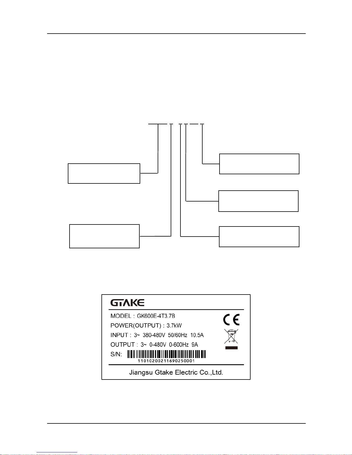
2.1 Model Explanation
Model shown on product nameplate indicates the series name, applicable type of power supply,
pow er class and the version of software and hardware, etc. via the combination of numbers,
symbols and letters.
GK600 E - 4 T 7.5 B
Fig. 2-1 Product model explanation
2.2 Nameplate Information
Fig. 2-2 Nameplate information
Dedicated drive
E:Elevator
4:Power 400 V AC
T:Power triphase
B: Brake chopper inbuilt
Product Platform
Chapter 2 Product Information GK600E User Manual
- 8 -
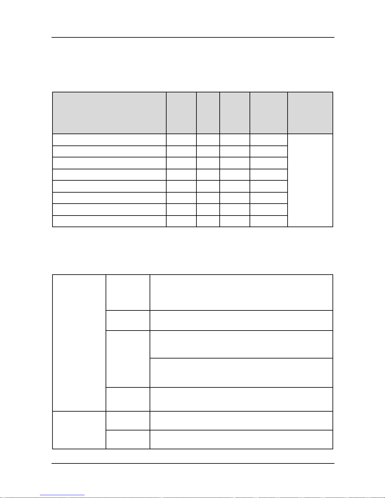
2.3 Information of Product Model
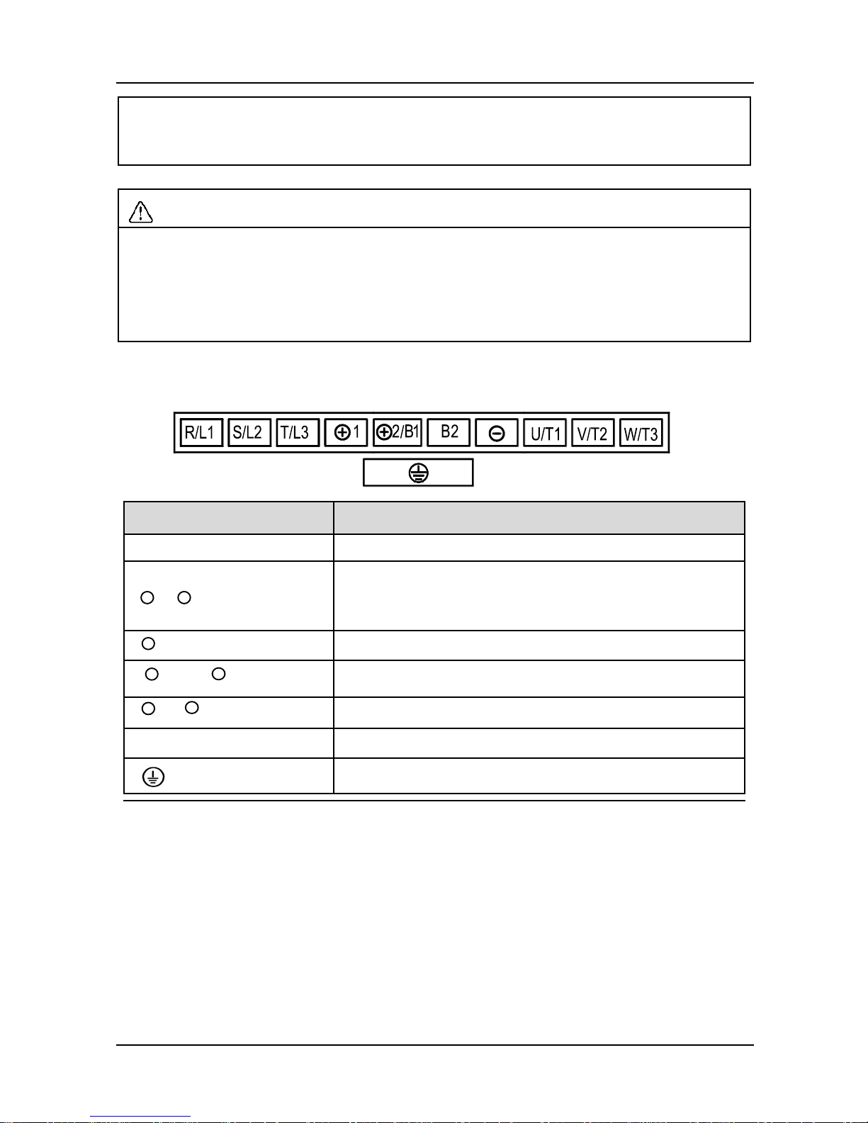
Table 2-1 Product model and technical data
■ GK600E-4T □□□, three-phase 400V input, heavy duty
Drive model
Pow er
rating
(kW)
Rated
output
current
(A)
Rated
input
current
(A)
Applicable
motor (kW)
Brake
chopper
GK600E-4T3.7B
3.7
9.0
10.5
3.7
Inbuilt
GK600E-4T5.5B
5.5
13
14.6
5.5
GK600E-4T7.5B
7.5
17
20.5
7.5
GK600E-4T11B
11
24
29
11
GK600E-4T15B
15
30
35
15
GK600E-4T18.5B
18.5
39
44
18.5
GK600E-4T22B
22
45
50
22
GK600E-4T30B
30
60
65
30
2.4 Technical Features of GK600E
Table 2-2 Technical Features of GK600E
Pow er input
Rated input
voltage
3-phase
AC380V/AC400V/
AC415V/AC440V/AC460V
Frequency
50Hz/60Hz, tolerance ±5%
Voltage
range
Continuous voltage fluctuation ±10%, short fluctuation
-15%~+10%, i.e. 400V: 323V~528V
(emergency input: UPS 220VAC, 1-phase)
Voltage out-of-balance rate <3%, distortion rate as per the
requirements of IEC61800-2
Rated input
current
See Section 2.3
Pow er output
Applicable
motor (kW)
See Section 2.3
Rated
current (A)
See Section 2.3
GK600E User Manual Chapter 2 Product Information
- 9 -
Output
voltage (V)
3-phase: 0~ rated input voltage, error < ±3%
Output
frequency
(Hz)
0.00~ 600.00Hz; unit: 0.01Hz
Overload
capacity
150% - 1min, 180% - 10s, 200% - 0.5s every 10 min
Control
characteristics
V/f patterns
V/f control
Range of
speed
regulation
1:100
Control
characteristics
Speed
accuracy
±0.5%
Start
torque
0.5Hz: 180%
Basic
functions
Start
frequency
0.00~ 600.00Hz
Accel/
Decel time
0.00~60000s
Switching
frequency
0.7kHz~16kHz
Frequency
setting
Digital setting + control panel ∧/∨
Digital setting + terminal UP/DOWN
Communication
Analog setting (AI1/AI2/EAI)
Terminal pulse setting
Motor
start-up
methods
Started from starting frequency
DC brake start-up
Flying start
Motor stop
methods
Ramp to stop
Coast to stop
Ramp stop + DC brake
Basic
functions
Dynamic
braking
capacity
Brake chopper working voltage: 650V-750V
Service time: 0-100.0s; brake chopper is inbuilt as default
for GK600E lift dedicated drives at GTAKE
DC brake
capacity
DC brake start frequency: 0.00~600.00Hz
DC brake current: 0.0~100.0%
DC brake time: 0.0~30.00s
Chapter 2 Product Information GK600E User Manual
- 10 -
Basic
functions
Input
terminals
7 digital inputs, one of which can be used for high-speed
pulse input, and compatible with active open collectors
NPN, PNP and dry contact input.
2 analog inputs, one of which is voltage/current
programmable, and the other supports voltage only.
Output
terminals
1 high-speed pulse output, 0~50kHz square wave signal
output. It can output signals such as frequency setting, or
output frequency, etc.
1 digital output
2 relay output
1 analog output, voltage/current output programmable; can
output signals such as frequency setting, or output
frequency, etc.
Protection
functions
Refer to Chapter 7- Troubleshooting
Environment
Place of
operation
Indoors, no direct sunlight, free from dust, corrosive
gases, flammable gases, oil mist, water vapor, water drop
or salt, etc.
Altitude
0-2000m . De-rate 1% for every 100m when the altitude is
above 1000 meters
Ambient
temperature
-10℃-40℃. The rated output current should be derated
1% for every 1℃ when the ambient is 40℃-50℃
Relative
humidity
0~95%, no condensation
Vibration
Less than 5.9m/s2 (0.6g)
Storage
temperature
-40℃~+70℃
Others
Efficiency at
rated Amps
Rated power
7.5kW and below : ≥93%
11~ 30kW: ≥ 95%
Installation
wall-mounted
IP grade
IP20
Cooling
method
Forced air cooling
GK600E User Manual Chapter 2 Product Information
- 11 -
2.5 Parts Drawing
a) GK600E-4T15B and below b) GK600E-4T18.5B ~ GK600E-4T30B
Fig. 2-3 Parts drawing
铭牌
下壳体
安装孔
底板
风扇罩
防尘盖板
操作面板
盖板
中壳体
盖板
操作面板
安装孔
机箱
铭牌
风扇
托板
Fan cov er
Dust cover
Control
panel
Cov er
Control
panel
Cov er
Base plate
Mounting
holes
Mounting
holes
Lower
casing
Nameplate
Middle casing
Control
panel
Fans
Enclosure
Nameplate

Chapter 2 Product Information GK600E User Manual
- 12 -
2.6 Appearance, Mounting Dimensions and Weight
a) GK600E-4T3.7B ~ GK600E-4T15B
b) GK600E-4T18.5B ~ GK600E-4T30B
Fig. 2-4 External dimensions
GK600E User Manual Chapter 2 Product Information
- 13 -
Table 2-3 Appearance, mounting dimensions and weight
Model
External and installation dimensions (mm)
Weight
(kg)
W H D
W1
H1
H2
Mounting
hole dia.
GK600E-4T3.7B
120
245
169
80
233
220
5.5
2.9
GK600E-4T5.5B
145
280
179
105
268
255
5.5
3.9
GK600E-4T7.5B
GK600E-4T11B
190
365
187
120
353
335 6 6.2
GK600E-4T15B
GK600E-4T18.5B
270
475
220
170
460
435
8
15.5
GK600E-4T22B
GK600E-4T30B
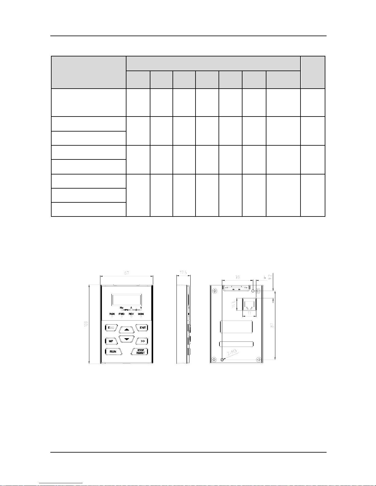
2.7 External Dimensions of Control Panel
Control panel model of GK600E series Elevator Dedicated Drives is KBU-BX1 whose
appearance and external dimensions are shown in Fig. 2-5.
Fig. 2-5 External dimensions of KBU-BX1
2.8 External Dimensions of Control Panel Bracket
A bracket should be provided to support the panel and a hole in the cabinet needs to be opened
when the control panel KBU-BX1 needs to be remotely used. Bracket model is KBU-DZ1
whose external dimensions are shown in Fig. 2-6 a). Fig. 2-6 b) shows applicable hole
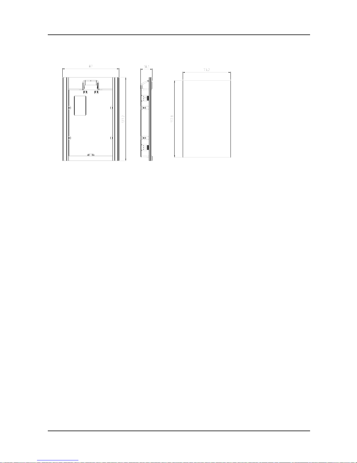
Chapter 2 Product Information GK600E User Manual
- 14 -
dimensions in the cabinet.
a) External dimensions of KBU-DZ1 b) Hole dimensions in the cabinet
Fig. 2-6 External dimensions of KBU-DZ1 and cabinet hole dimensions
Panel TH Hole WTH
1.2mm 73.2mm
1.5mm 74.4mm
2mm 75.5mm
GK600E User Manual Chapter 3 Installation and Wiring
- 15 -
Chapter 3 Installation and Wiring
3.1 Installation Environment
1) Ambient temperature is in the range of -10℃~ 40℃.
2) Drive should be installed on surface of flame retardant object, with adequate surrounding
space for heat dissipation.
3) Installation should be performed w here vibration is less than 5.9m/s2 (0.6g).
4) Protect from moisture and direct sunlight.
5) Protect the cooling fan by avoiding oil, dust and metal particles.
6) Do not expose to an atmosphere with flammable gases, corrosive gases, explosive gases
or other harmful gases.
7) Prevent drilling residues, wire ends and screws falling into drive.
8) Ventilation part of the drive should be installed outside from harsh environment (e.g. textile
facilities with fiber particles and chemical facilities filled with corrosive gases.
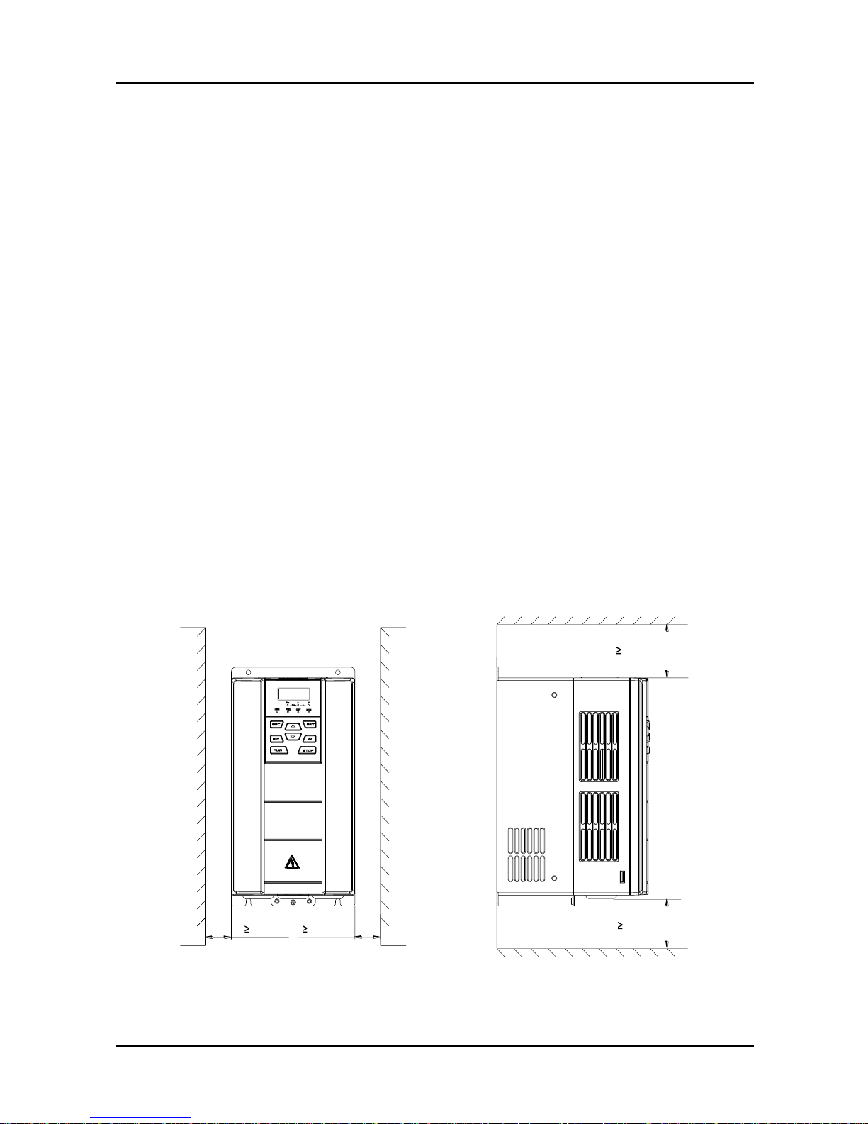
3.2 Minimum Mounting Clearances
To ensure favorable heat dissipation, mount the drive upright on a flat, vertical and level surface
as per Fig. 3.1. For installation inside cabinet, the product shall be mounted side by side to the
greatest extent while adequate surrounding space shall be preserved for favorable heat
dissipation.
Fig. 3-1 Minimum mounting clearances of GK600E-4T15B and below
空气流通位置
100mm
100mm
空气流通位置
30mm
30mm
Vent clearance
Vent clearance
Chapter 3 Installation and Wiring GK600E User Manual
- 16 -
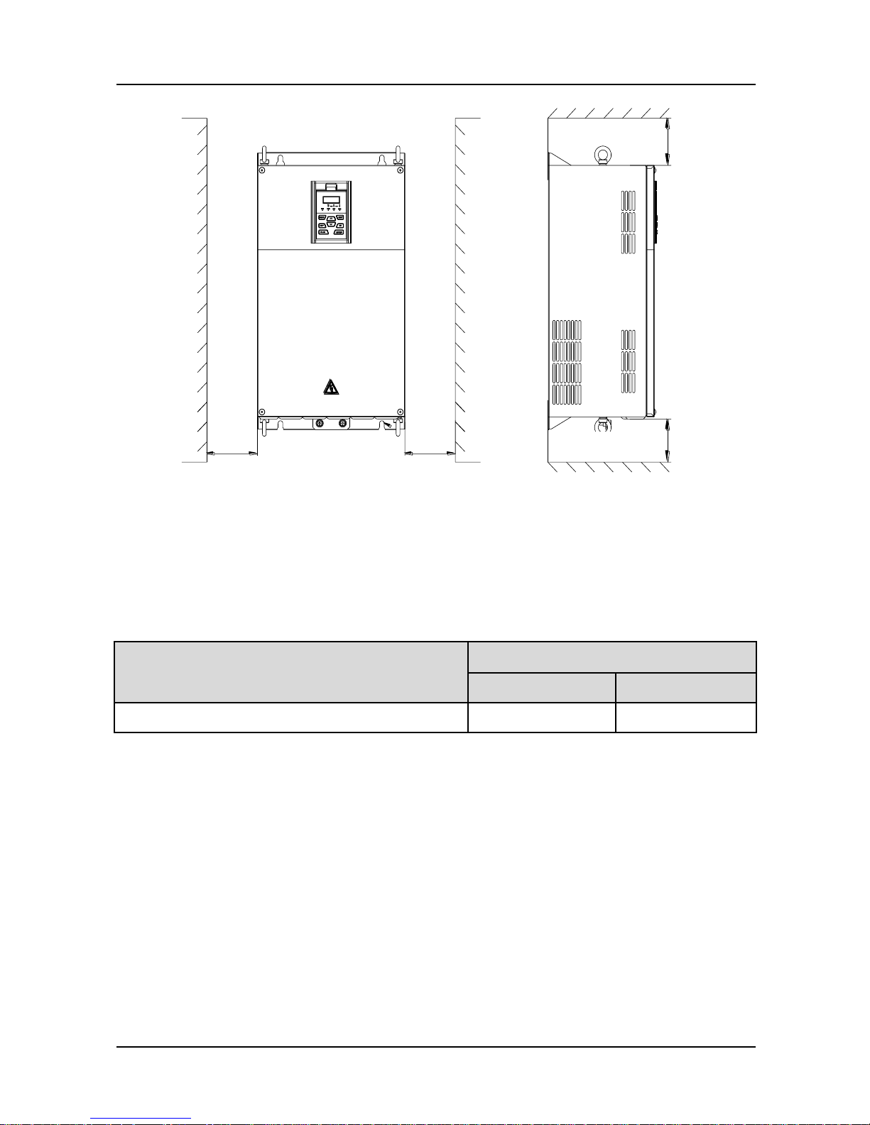
Fig. 3-2 Minimum mounting clearances of GK600E-4T18.5B and above
ATTENTION:
When mounting a drive GK600E-4T18.5B or above, the minimum mounting clearances as
set forth in Table 3-1 should be assured.
Table 3-1 Requirement of minimum mounting clearances
Drive model
Mounting clearances (mm)
A
B
GK600E-4T18.5B ~ GK600E-4T30B
≥50
≥200
3.3 Remove & Mount Control Panel and Cover
3.3.1 Remove and Mount Control Panel
Remove control panel
Press the buckle of control panel as indicated by number "1" in Fig. 3-3, then pull the panel
out to release as indicated by "2".
Mount control panel
Slightly slant the panel in the direction as indicated by number "1" in Fig. 3-4 and align it to
clamping port at lower part of panel bracket, then press it in as indicated by "2". When a
"click" sound heard, it indicates clamping has been properly made.
空气流通位置
B
空气流通位置
B
A A
Vent clearance
Vent clearance

GK600E User Manual Chapter 3 Installation and Wiring
- 17 -
Fig. 3-3 Remove the control panel Fig. 3-4 Mount the control panel
3.3.2 Open & Mount the Covers of GK600E-4T3.7B ~ GK600E-4T15B
Remove the control panel
Use the remove method as stated in Section 3.3.1.
Open the cover
Method 1: loosen the captive cover screws as shown in Fig. 3-5 a) (provided only for
11/15kW model), hold the left and front sides of middle housing with left hand, put the right
thumb into the buckle and press tightly on cover with the other four fingers, pull the lower
part of the cover out to release, as indicated by number "2".
Method 2: loosen the captive cover screws, as indicated by number "1" in Fig. 3-5 b)
(provided only for 11/15kW model), use a sizeable slotted screwdriver to push the buckle
slightly at the low er part of the cover to make buckle naturally off the groove, as indicated
by "2", pull the cover out to release, as indicated by number "3".
a) Method 1 b) Method 2
Fig. 3-5 Open the cover
1
2
1
2
1
1
螺丝刀
Screwdriver
Chapter 3 Installation and Wiring GK600E User Manual
- 18 -
Mount the cover
On the completion of w iring, insert the buckle at higher part of the cover into the grooves at
middle housing as indicated by number "1" in Fig. 3-6, then push in the lower part of the
cover as indicated by "2". When a "click" sound heard, it indicates clamping has been
properly made. Tighten the screws (provided only for 11/15kW model) in buckle grooves
as finish.
Fig. 3-6 Mount the cover
Mount the control panel
Use the mounting method as stated in Section 3.3.1.
ATTENTION:
Be sure to remove the control panel before opening the cover and mount the cover before
mounting the control panel.
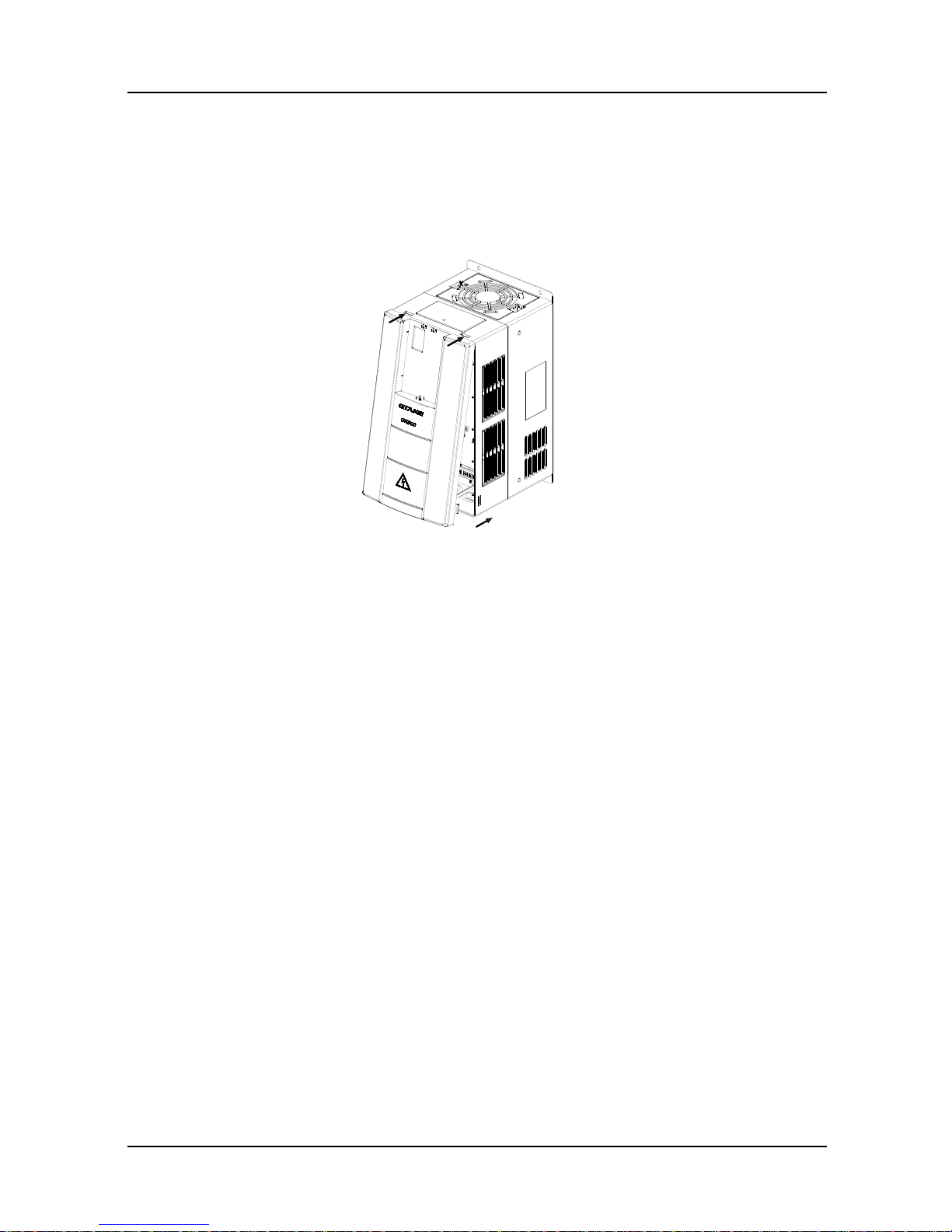
3.3.3 Open & Mount the Covers of GK600E-4T18.5B and above
Remove the control panel
Use the remove method as stated in Section 3.3.1.
Open the lower cover
Loosen the two captive cover screws at lower part of the lower cover by using cross
screwdriver, as indicated by number "1" as shown in Fig. 3-7, then pull the cover out and
up as indicated by number "2".
Open the upper cover
Loosen the two captive cover screws at lower part of the lower cover by using cross
screwdriver, as indicated by number "3" and “4” as shown in Fig. 3-7, then pull the cover
out and up as indicated by number "5".
1
1
2
GK600E User Manual Chapter 3 Installation and Wiring
- 19 -
Fig. 3-7 Open & mount the covers
Mount the upper cover
Insert the upper part of the cover into mounting groove as shown in Fig. 3-8 (left), close the
upper cover, use cross screwdriver to tighten the four captive screws, as indicated by
number “1” and "2".
Mount the lower cover
Insert the lower cover into upper cover in the direction as indicated by number 3 in Fig. 3-8
(right), close the lower cover and tighten the two captive screws, as indicated by number
"4".
Fig. 3-8 Mount the upper and lower covers
Mount the control panel
Use the mounting method as stated in Section 3.3.1.
1
1
2
3
4
4
5
3
1
2
2
1
3
4
4

Chapter 3 Installation and Wiring GK600E User Manual
- 20 -
ATTENTION:
Be sure to remove the control panel before opening the cover and mount the cover before
mounting the control panel.
GK600E User Manual Chapter 3 Installation and Wiring
- 21 -
3.4 Configuration of Peripheral Devices
3.4.1 Standard Configuration of Peripheral Devices
Fig. 3-9 Standard configuration of peripheral devices
Output AC Reactor
Braking Resistor
Pow er Supply
Circuit Breaker or RCD
Contactor
Input AC Reactor
DC Choke
Output Filter
AC Motor Drive
PE
Motor
PE
Input Filter
Chapter 3 Installation and Wiring GK600E User Manual
- 22 -
3.4.2 Instructions for Peripheral Devices
Table 3-2 Instructions for peripheral devices
Name
Instructions
Pow er
supply
Input three-phase AC pow er supply should be in the range as specified in
this manual
Circuit
breaker
Purpose: disconnect power supply and protect the equipments in case of
abnormal overcurrent occurs
Type selection: breaking current of circuit breaker is defined to be 1.5~2
times the rated current of the drive
Breaking time characteristic of circuit breaker should be selected based on
overload protection time characteristic of the drive
RCD
Purpose: since the drive outputs PWM HF chopping voltage, HF leakage
current is inevitable
Type selection: type B dedicated RCD is recommended
Contactor
For safety's sake, do not frequently close and break the contactor since this
may bring about equipment faults
Do not control the start & stop of the drive directly through switch on and off
the contactor since this w ill result in a reduction on the product life
Input AC
reactor or
DC choke
Improve power factor
Reduce the impact of imbalanced three-phase input AC power supply on
the system
Suppress higher harmonics and reduce the conducted and radiated
interference to peripheral devices
Restrict the impact of impulse current on rectifier bridges
Input filter
Reduce conducted interference from power supply to the drive, improve the
immunity of the drive from noise
Reduce conducted and radiated interference of the drive to peripheral
devices
Brake unit
and
braking
resistor
Purpose: consume motor feedback energy to attain quick brake
Type selection: Contact GTAKE technical personnel for type selection of
brake unit. Refer to type selection of braking resistor in Table 3-3 Type
Selection of Peripheral Devices.
Output filter
Reduce conducted and radiated interference of the drive to peripheral
devices
Output AC
reactor
Avoid the motor insulation damage result from harmonic voltage
Reduce frequent protection from the drive caused by leakage current
In case the cable connecting drive and motor is over 100 meters, output AC
reactor recommended
Motor
Should match the drive
GK600E User Manual Chapter 3 Installation and Wiring
- 23 -
3.4.3 Selection of Peripheral Devices
Table 3-3 Selection of peripheral devices
■GK600E-4T B, Three phase 400V input
Drive model
Circuit
breaker
(A)
Contactor(A)
Brake resistor /Brake chopper*
Pow er (W)
Resistance (Ω)
GK600E-4T3.7B
16
12
450
≥75
GK600E-4T5.5B
20
18
500
≥75
GK600E-4T7.5B
32
25
500
≥75
GK600E-4T11B
40
32
800
≥30
GK600E-4T18.5B
63
50
1300
≥16
GK600E-4T22B
63
50
1500
≥16
GK600E-4T30B
100
65
2000
≥16
* On the premise of fulfilling brake requirement, brake resistance value might be bigger than the minimum value as
stated in the table. Failure to comply may result in damage to the resistor and the drive. Brake resistors are not
built in and need to be sourced additionally.
Chapter 3 Installation and Wiring GK600E User Manual
- 24 -
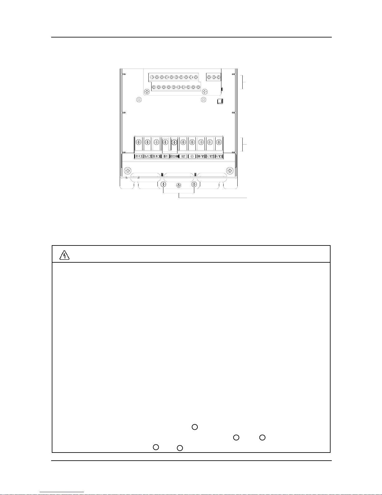
3.5 Terminal Configuration
Fig. 3-10 Terminal configuration
3.6 Main Circuit Terminals and Wiring
WARNING
Only qualified personnel familiar w ith AC motor drives and passenger lift are allowed to
implement wiring. Failure to comply may result in equipment damage and/or personnel
injury even death.
Wiring should be in strict accordance with this manual, otherwise hazard of electric
shock or equipment damage exists.
Make sure input power supply has been completely disconnected before wiring
operation. Failure to comply will result in personnel injury even death.
All w iring operations and lines should comply with EMC and national and local industrial
safety regulations and/or electrical codes. The conductor diameter should be in
accordance with recommendations of this manual. Otherwise, hazard of equipment
damage, fire, and/or personnel injury exists.
Since leakage current of the drive may exceed 3.5mA, for safety's sake, the drive and
the motor must be grounded so as to avoid hazard of electric shock.
Be sure to perform w iring in strict accordance with the drive terminal marks. Never
connect three-phase power supply to output terminals U/T1, V/T2 and W/T3. Failure to
comply will result in equipment damage.
Only mount braking resistors at terminals and B2.
When needed, only mount DC reactors at terminals and , and remove the
jumper connected between and . Never connect the jumper and DC reactor to
控制回路端子
主回路端子
接地端子
Control circuit terminals
Main circuit terminals
+ 2/B1
+ 1
+ 2
+ 1
+ 2
Grounding terminals
GK600E User Manual Chapter 3 Installation and Wiring
- 25 -
other terminals since this will result in short circuit and equipment damage.
Wiring screws and bolts for main circuit terminals must be screwed tightly. Failure to
comply may result in faults and/or equipment damage.
ATTENTION
Signal wires should be away from main power lines to the best of possibility. In the
event that this cannot be ensured, vertical cross arrangement should be adopted,
reducing EMI interference to the signal wires as much as possible.
In case the motor cable exceeds 100m, an appropriate output reactor should be
mounted.
3.6.1 Main Circuit Terminals of GK600E-4T3.7B ~ GK600E-4T30B
Terminal marks
Designation and function of terminals
R/L1, S/L2, T/L3
Three-phase AC input terminals
,
DC reactor connection terminals. Connected w ith a
jumper as factory default
, B2
Built-in brake unit connection terminals*
,
DC input terminals of externally mounted brake unit
,
DC power supply input terminals
U/T1, V/T2, W/T3
Three-phase AC output terminals
Ground terminal PE
-
+ 1
+ 2/B1
+ 2/B1
+ 2/B1
-
+ 1
Chapter 3 Installation and Wiring GK600E User Manual
- 26 -
3.6.2 Terminal Screw and Wiring Requirement
Table 3-4 Terminal screw and wiring requirement
■GK600E-4T B Three-phase 400V input
Drive model
Pow er terminal
Ground terminal
Cable
requirement
(mm2)
Screw
Torque
(kgf.cm)
Cable
requirement
(mm2)
Screw
Torque
(kgf.cm)
GK600E-4T3.7B
2.5
M4
14±0.5
2.5
M4
14±0.5
GK600E-4T5.5B
4
M4
14±0.5
4
M4
14±0.5
GK600E-4T7.5B
4
M4
14±0.5
4
M4
14±0.5
GK600E-4T11B
6
M5
28±0.5
6
M4
14±0.5
GK600E-4T15B
10
M5
28±0.5
10
M4
14±0.5
GK600E-4T18.5B
10
M6
48±0.5
10
M6
48±0.5
GK600E-4T22B
16
M6
48±0.5
16
M6
48±0.5
GK600E-4T30B
25
M6
48±0.5
16
M6
48±0.5
3.7 Control Terminal Wiring
WARNING
Only qualified personnel familiar w ith AC motor drives and passenger lift are allowed to
implement wiring. Failure to comply may result in equipment damage and/or personnel
injury even death.
Wiring should be in strict accordance with this manual, otherwise hazard of electric
shock or equipment damage exists.
Make sure input power supply has been completely disconnected before wiring
operation. Failure to comply will result in personnel injury even death.
All w iring operations and lines should comply with EMC and national and local industrial
safety regulations and/or electrical codes. The conductor diameter should be in
accordance with recommendations of this manual. Otherwise, hazard of equipment
GK600E User Manual Chapter 3 Installation and Wiring
- 27 -
damage, fire, and/or personnel injury exists.
Screw s or bolts for terminal wiring must be screwed tightly.
AC 220V signal is prohibited from connecting to terminals other than control terminals
RA, RB and RC.
ATTENTION
Signal wires should be away from main power lines to the best of possibility. If this
cannot be ensured, vertical cross arrangement should be adopted, reducing EMI
interference to the signal wires as much as possible.
The encoder must be provided with shielded cables whose shielded layer must be
properly grounded.
Chapter 3 Installation and Wiring GK600E User Manual
- 28 -
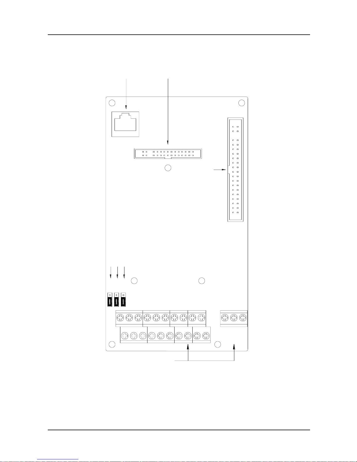
3.7.1 Control Board Diagram
Fig. 3-11 Control board diagram
OFF
ON
AI1 AO1485
I
VV
I
S2S1 S3
主信号接口
操作面板485接口
扩展卡接口
用户信号端子
端
子
通
讯
终
端
电
阻
选
择
模
拟
量
输
入
1
电
压
电
流
选
择
模
拟
量
输
出
1
电
压
电
流
选
择
Control panel 485 interface
Option board interface (engaged
by EPC-TM1 as default)
Main signal
interf ace
S1: Terminal resistor selection for terminal communication
S2: Analog input 1 voltage/current option
S3: Analog output 1 voltage/current option
User signal
terminal
GK600E User Manual Chapter 3 Installation and Wiring
- 29 -
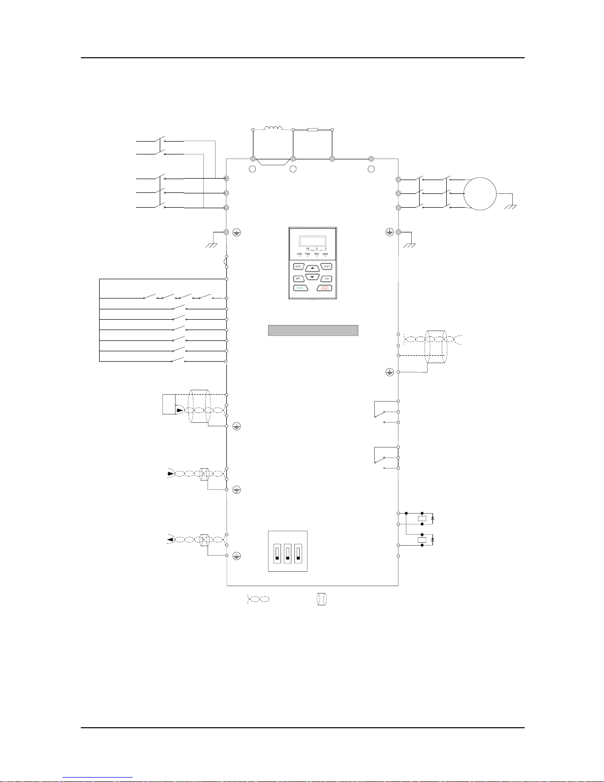
3.7.2 Wiring Diagram
Fig. 3-12 Wiring diagram
M
DC Reactor
Jumper
Braking
Resistor
Motor
Ground
R/L1
S/L2
T/L3
U/T1
V/T2
W/T3
Power
Supply
Ground
++
1
2/B1
B2
UPS
1-phase
220VAC
Three-phase
Power Supply
380V-460V
50/60Hz
+24V
PLC
X1
X2
X3
X4
X5
X6
COM
Enable
Run Fwd
Run Rev
Multi-speed sel 1
Multi-speed sel 2
Multi-speed sel 3
RA
RB
RC
+24V
Y1
Y2/DO
COM
+10V
AI1
GND
Relay Output
250V AC/3A
30V DC/3A
Open Collector Output 1
Open Collector Output 2
High-speed Pulse Output
Option Board Interface
CN2
GK600E
Jumper
Analog In Reference
Voltage
POT
OFFONV
IVI
485 AI1 AO1
AI2
GND
485 MODBUS
Communication
485+
485-
AO1
GND
GND
Paired
Cable
Shielded
Cable
Analog In
DC: 0~10V/0~20mA
Analog In
DC:-10V~10V
Analog Out
DC:0~10V/0~20mA
Control Panel
-
KM1
KM4
KM1
KM2
KM3
Safety Contacts
X7 (On Option Board)
Emergency Speed
Relay Output
(On Option Board)
250V AC/3A
30V DC/3A
RA
RB
RC
KM2 KM3
Chapter 3 Installation and Wiring GK600E User Manual
- 30 -
3.8 Control Terminal Specification
Table 3-5 Control terminal specification
Category
Terminal
Terminal
designation
Specification
Analog
input
+10V
Analog input
reference
voltage
10.3V ±3%
Maximum output current 25mA
The resistance of external potentiometer
should be larger than 400Ω
GND
Analog ground
Isolated from COM interiorly
AI1
Analog input 1
0~20mA: input impedance - 500Ω, maximum
input current - 25mA
0~10V: input impedance - 22kΩ,
maximum input voltage - 12.5V
Switch S2 on control board for jumping from
0~20mA and 0~10V, factory default: 0~10V
AI2
Analog input 2
-10V~10V: input impedance - 25kΩ
Range: -12.5V~+12.5V
Analog
output
AO1
Analog output 1
0~20mA: impedance - 200Ω~500Ω
0~10V: impedance ≥ 10k
Switch S3 on control board for jumping from
0~20mA to 0~10V, factory default: 0~10V
GND
Analog ground
Isolated from COM interiorly
Digital
input
+24V
+24V
24V±10%, Isolated from GND interiorly
Maximum load - 200mA
PLC
Digital input
Common
terminal
Used for sw itching between high and low
levels, short-circuited with +24V when
delivery, i.e. low value of digital input valid
External power input
COM
+24V ground
Isolated from GND interiorly
X1~X6
Digital input
Terminals 1~5
Input: 24VDC, 5mA
Range of frequency: 0~200Hz
Range of voltage: 10V~30V
X7
Digital input (on
option board)
Digital input: same as X1~X5
Digital
output
Y1
Open collector
output
Range of voltage: 0~24V
Range of current: 0~50mA
Y2/DO
Open collector
out / Pulse out
Open collector output: same as Y1
Pulse output: 0~50kHz;
GK600E User Manual Chapter 3 Installation and Wiring
- 31 -
Category
Terminal
Terminal
designation
Specification
Relay
output
RA/RB/RC
Control board
relay output
RA-RB: NC; RA-RC: NO
Contact capacity: 250VAC/3A, 30VDC/3A
RA/RB/RC
Option board relay
output
Same as control board relay output
Terminal
485
Interface
485+
485 differential
signal +
Rate:
4800/9600/19200/38400/57600/115200bps
485−
485 differential
signal -
Maximum distance - 500m (standard network
cable used)
GND
485
communication
shield grounding
Isolated from COM interiorly
Control
panel
485
interface
CN4
Control panel
485 interface
Maximum communication distance is 15m
when connected to Control panel
Use standard network cable
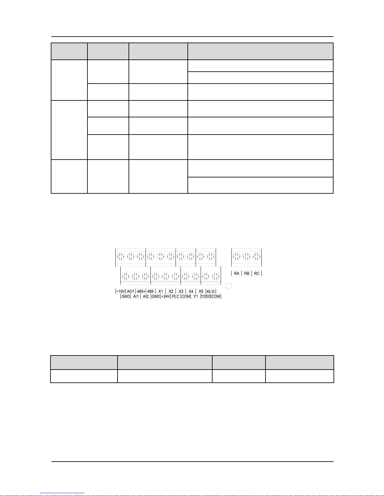
3.9 Control Terminal Usage
3.9.1 Lay-out of Control Terminals
Fig. 3-13 Lay-out of control terminals
3.9.2 Control Terminal Screw and Wiring Requirement
Table 3-6 Terminal screw and wiring specification
Cable type
Cable requirement (mm2)
Screw
Torque (kgf.cm)
Shielded cable
1.0
M3
5±0.5
3.9.3 Instructions of Analog Input/Output Terminals
Being particularly vulnerable to noise, analog input & output signal cables should be as short as
possible, shielded, and their shielded layers should be properly grounded close to the side of
drive. The cables should not exceed 20m.

Chapter 3 Installation and Wiring GK600E User Manual
- 32 -
Control cables shall be kept no less than 20cm away from main circuit and strong current lines
(e.g. power lines, motor lines, relay lines and contactor lines) and should not be arranged in
parallel with strong current lines. In case it is inevitable to intersect strong current line, vertical
wiring is recommended to avoid drive faults as a result of noise.
Where analog input & output signals are severely interfered, the side of analog signal source
should be provided w ith filter capacitor or ferrite core.
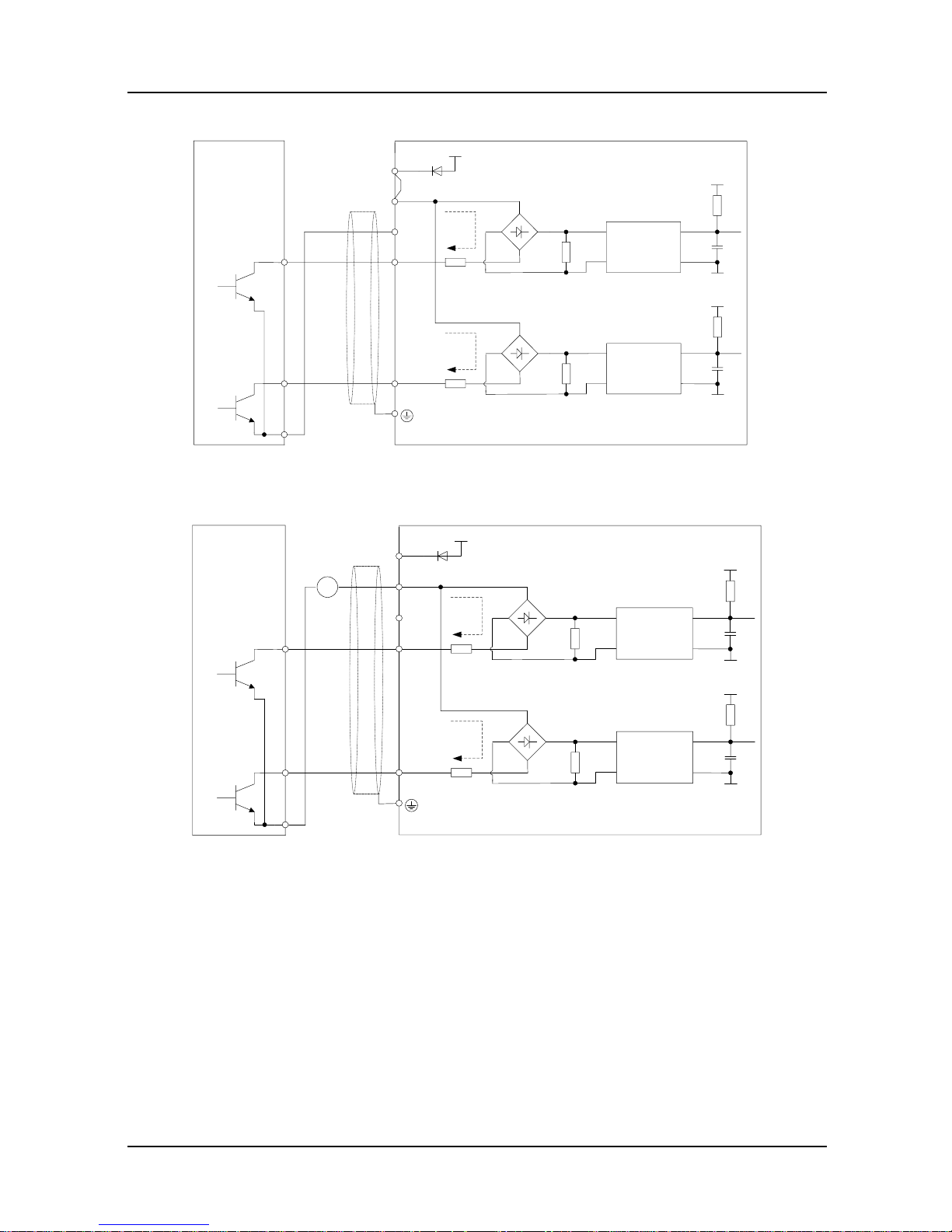
3.9.4 Instructions of Digital Input/Output Terminals
Digital input & output signal cables should be as short as possible, shielded, and their shielded
layers should be properly grounded close to the side of drive. The cables should not exceed
20m. When active drive is selected, take necessary filtering measures against power crosstalk,
for which dry contact control is recommended.
Control cables shall be kept no less than 20cm away from main circuit and strong current lines
(e.g. power lines, motor lines, relay lines and contactor lines) and should not be arranged in
parallel with strong current lines. In case it is inevitable to intersect strong current line, vertical
wiring is recommended to avoid drive faults as a result of noise. Operating instructions for
sw itching value input terminal
Instructions of digital input terminal
Dry contact
1
6
X1
X6/DI
COM
+24V
PLC
+3.3V
GND
24V
Drive
External
Controller
Shielded
Cable
Near-end
Ground
+-
Jumper
OC
+3.3V
GND
+-
OC
Fig. 3-14 Internal power supply dry contact

GK600E User Manual Chapter 3 Installation and Wiring
- 33 -
1
6
X1
X6/DI
COM
+24V
PLC
+3.3V
GND
24V
Drive
External
Controller
Shielded
Cable
Near-end
Ground
+-
OC
+3.3V
GND
+-
OC
+ -
20~30V
Fig. 3-15 External power supply dry contact
ATTENTION:
When external power supply is used, the jumper between +24V and PLC must be removed.
Otherwise, it may result in equipment damage.
The voltage range of external power supply should be DC20~30V. Otherwise, normal
operation could not be assured and/or result in equipment damage.
Chapter 3 Installation and Wiring GK600E User Manual
- 34 -
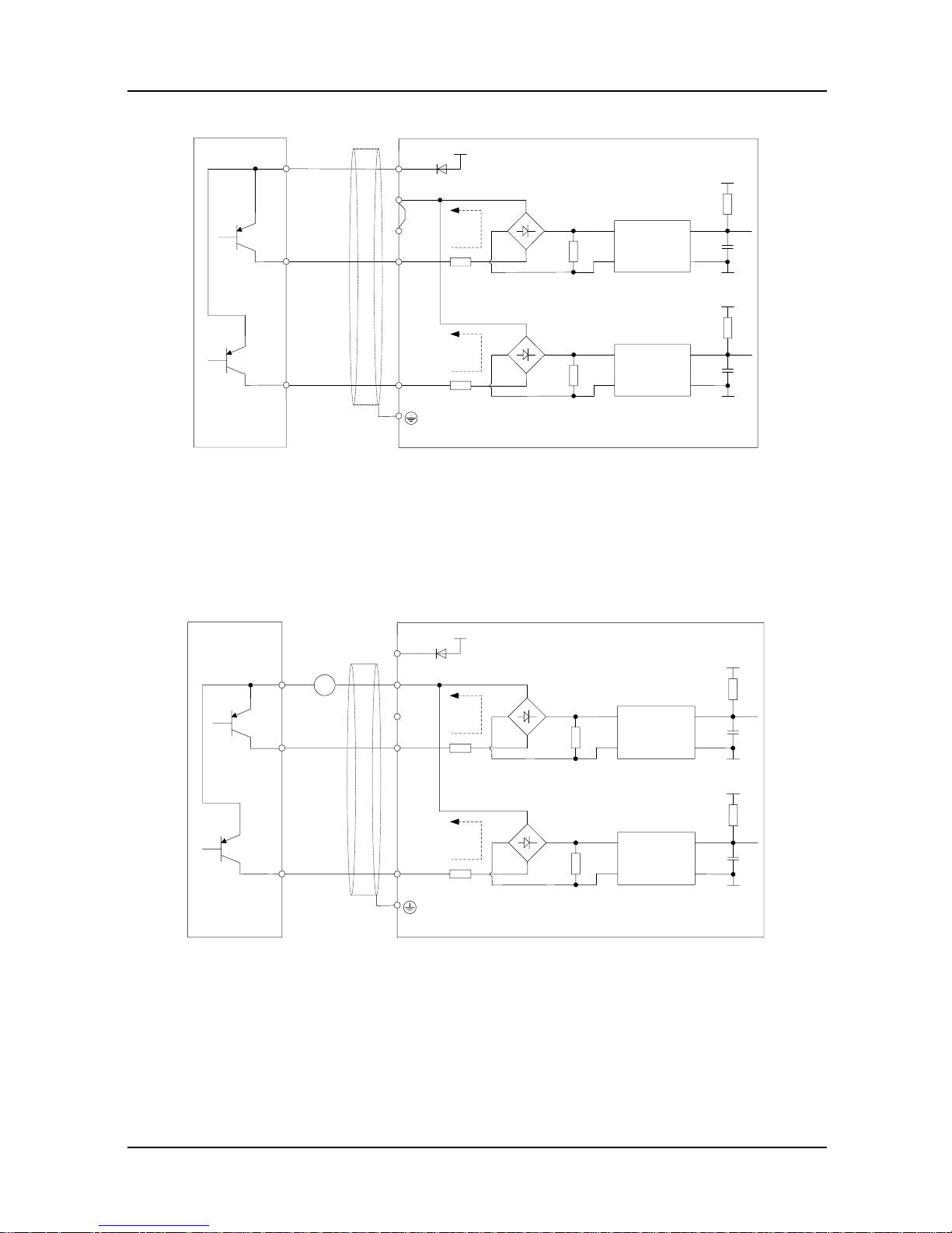
Open collector NPN connection
X1
X6/DI
COM
+24V
PLC
+3.3V
GND
24V
Drive
Shielded
Cable
Near-end
Ground
+-
Jumper
OC
+3.3V
GND
+-
OC
1
6
External
Controller
Fig. 3-16 Internal power supply open collector NPN connection
X1
X6/DI
COM
+24V
PLC
+3.3V
GND
24V
Drive
Shielded
Cable
Near-end
Ground
+-
OC
+3.3V
GND
+-
OC
+ -
20~30V
1
6
External
Controller
Fig. 3-17 External power supply open collector NPN connection
ATTENTION:
When external power supply is used, the jumper between +24V and PLC must be removed.
The voltage range of external power supply should be DC20~30V, otherwise normal
operation could not be assured and/or hazard of equipment damage exists.
GK600E User Manual Chapter 3 Installation and Wiring
- 35 -
Open collector PNP connection
X1
X6/DI
COM
+24V
PLC
+3.3V
GND
24V
Drive
Shielded
Cable
Near-end
Ground
+-
Jumper
OC
+3.3V
GND
+-
OC
1
6
External
Controller
Fig. 3-18 Internal power supply open collector PNP connection
ATTENTION:
When PNP connection is adopted, it is necessary to remove the jumper between +24V and
PLC, and connect the jumper to PLC and COM.
X1
X6/DI
COM
+24V
PLC
+3.3V
GND
24V
Drive
Shielded
Cable
Near-end
Ground
+-
OC
+3.3V
GND
+-
OC
20~30V
1
6
External
Controller
+-
Fig. 3-19 External power supply open collector PNP connection
ATTENTION:
When external power supply is used, the jumper between +24V and PLC must be removed.
The voltage range of external power supply should be DC20~30V. Otherwise, normal
operation could not be assured and/or hazard of equipment damage exists.
Chapter 3 Installation and Wiring GK600E User Manual
- 36 -
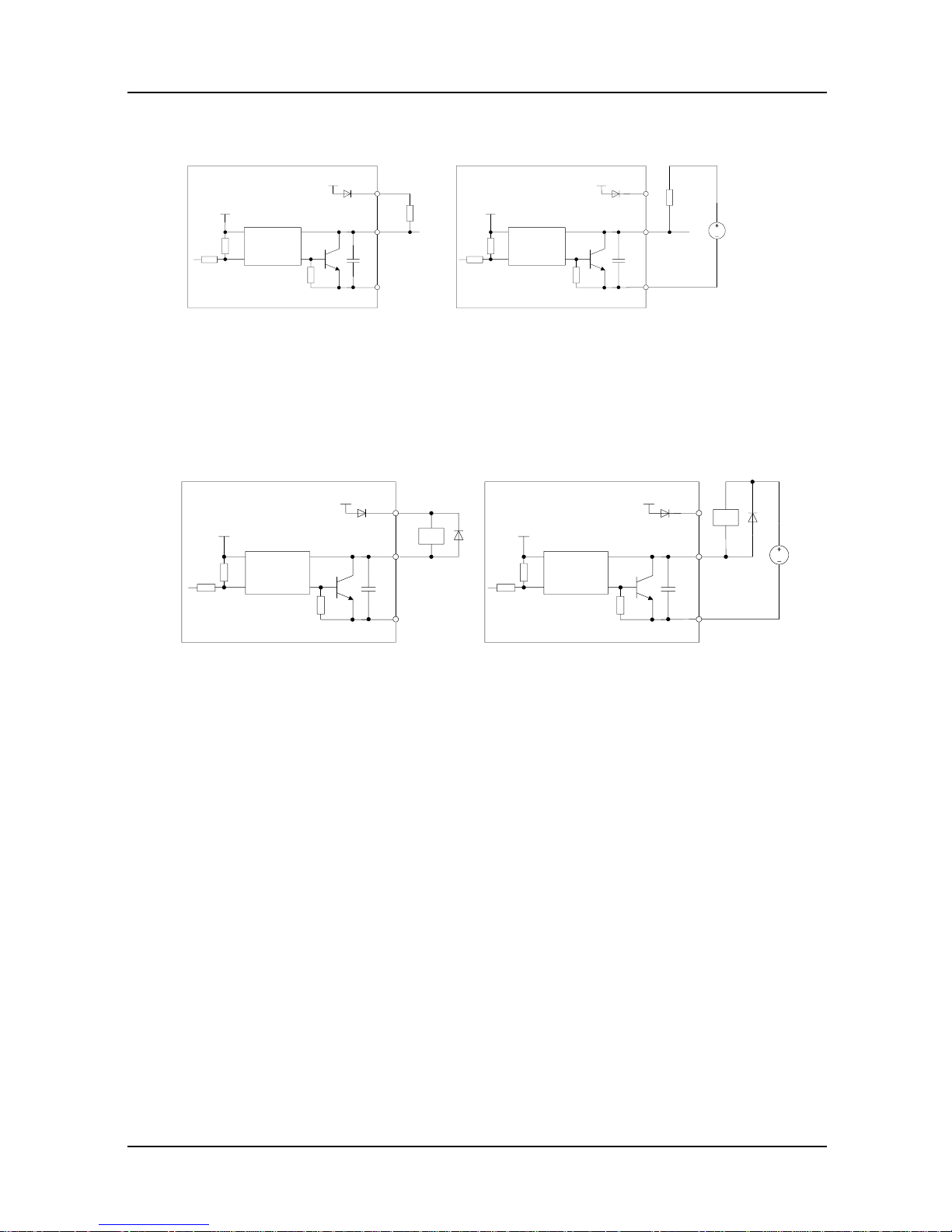
Instructions of digital output terminal
Instructions of Y1 and Y2/DO output terminals
a) Internal power supply b) External power supply
Fig. 3-20 Wiring when Y1 and Y2/DO output with pull-up resistor
ATTENTION:
When set to be pulse output, Y2/DO terminal shall output 0~50kHz pulse signal.
a) Internal power supply b) External power supply
Fig. 3-21 Wiring when Y1 and Y2/DO drive relay
ATTENTION:
When relay coil voltage is low er than 24V, a resistor as voltage divider should be mounted
between relay and output terminal, based on coil impedance.
Wiring instruction of relay output terminal
Control board of GK600E series drive is provided with a group of programmable relay dry
contact outputs. RA/RB/RC are relay contacts. RA and RB are normally closed, while RA
and RC are normally open. See parameter C1-02 for details.
ATTENTION:
In case inductive load (e.g. electromagnetic relay or contactor) is to be driven, a surge
voltage absorbing circuit such as RC absorbing circuit (note that its leakage current shall be
less than holding current of controlled contactor or relay), piezoresistor or fly-wheel diode
etc. shall be mounted (be sure to pay close attention to polarity in case of DC
electromagnetic circuit). Absorbing devices should be mounted close to the ends of relay or
contactor.
Y1、Y2/DO
COM
+24V
+5V
24V
Drive
OC
Y1、Y2/DO
COM
+24V
+5V
24V
Drive
OC
=30V
Pull-up
Resistor
Pull-up
Resistor
Y1、Y2/DO
COM
+24V
+5V
24V
Drive
OC
Y1、Y2/DO
COM
+24V
+5V
24V
Drive
OC
=30V
Relay Relay

GK600E User Manual Chapter 3 Installation and Wiring
- 37 -
3.10 Instruction of Signal Switches
Fig. 3-22 Jumper diagram of signal switching
3.11 EMI Solutions
Due to its working principle, the drive will inevitably produce certain noise that may influence
and disturb other equipment. Moreover, since the internal weak electric signal of drive is also
susceptible to the interference of drive itself and other equipment, EMI problems shall be
inevitable. In order to reduce or avoid the interference of drive to external environment and
protect drive against interference from external environment, this section makes a brief
description of noise abatement, ground handling, leakage current suppression and the
application of power line filters.
3.11.1 Noise Abatement
When peripheral equipment and drive share the power supply of one system, noise from the
drive may be transmitted to other equipment in this system via power lines and result in
misoperation and/or faults. In such a case, the following measures could be taken:
Mount input noise filter at input terminal of the drive;
Mount power supply filter at power input terminal of affected equipment;
Use isolation transformer to isolate the noise transmission path between other equipment
and the drive.
As the wiring of peripheral equipment and the drive constitutes a circuit, the unavoidable
earthing leakage current of the drive will cause equipment misoperation and/or faults.
Disconnect the grounding connection of equipment may avoid this misoperation and/or faults
Sensitive equipment and signal lines shall be mounted as far away from the drive as possible.
Designation
Function
Default
setting
S1
Selection of 485 termination resistor; ON :100Ω termination
resistor provided; OFF: no termination resistor
OFF
S2
Type Selection of AI1 analog signal:
I: current input (0~20mA); V: voltage input (0~10V)
V: 0~10V
S3
Type Selection of AO1 analog signal:
I: current output (0~20mA); V: voltage output (0~10V)
V: 0~10V
ON
OFF
AI1 AO1485
V
II
V
S2S1 S3
Chapter 3 Installation and Wiring GK600E User Manual
- 38 -
Signal lines should be provided with shielded layer and reliably grounded. Alternatively, signal
cable could be put into metallic conduits between which the distance shall be no less than
20cm, and shall be kept as far away from the drive, its peripheral devices, and cables as
possible. Never make signal lines in parallel with power lines or bundle them up.
Signal lines must orthogonally cross power lines if this cross is inevitable. Motor cables shall be
placed in thick protective screen like more than 2mm-thick pipelines or buried in cement groove,
also, power lines can be put into metallic conduit and grounded well with shielded cables.
Use 4-core motor cables of which one is grounded at close side of the drive and the other side
is connected to motor enclosure.
Input and output terminals of the drive are respectively equipped with radio noise filter and
linear noise filter. For example, ferrite common mode choke can restrain radiation noise of
power lines.
3.11.2 Grounding
Recommended ground electrode is shown in the figure below:
Drive
Other
Devices
PE
PE
Fig. 3-23 Grounding
Use to the fullest extent the maximum standard size of grounding cables to reduce the impedance
of grounding system.
Grounding wires should be as short as possible. Grounding point shall be as close to the drive as
possible.
One w ire of 4-core motor cables shall be grounded at the drive side and connected to grounding
terminal of motor at the other side. Better effect will be achieved if motor and drive are provided
with dedicated ground electrodes.
When grounding terminals of various parts of system are linked together, leakage current turns
into a noise source that may influence other equipment in the system, thus, grounding terminals of
the drive and other vulnerable equipment should be separated. Grounding cable shall be kept
away from inlet & output of noise-sensitive equipment.

GK600E User Manual Chapter 3 Installation and Wiring
- 39 -
3.11.3 Leakage Current Suppression
Leakage current passes through the line-to-line and ground distributed capacitors at input &
output sides of drive, and its size is associated with the capacitance of distributed capacitor and
the switching frequency. Leakage current is classified into ground leakage current and
line-to-line leakage current.
Ground leakage current not only circulates inside drive system, but may also influence other
equipment via ground loop. Such a leakage current may result in malfunction of RCD and other
equipment. The higher the switching frequency of drive is, the bigger the ground leakage current
will be. The longer the motor cables and the bigger the parasitic capacitance are, the bigger the
ground leakage current will be. Therefore, the most immediate and effective method for
suppression of ground leakage current is to reduce the sw itching frequency and minimize the
length of motor cables.
The higher harmonics of line-to-line leakage current that passes through between cables at output
side of drive will accelerate the aging of cables and may bring about malfunction of other
equipment. The higher the switching frequency of drive is, the bigger the line-to-line leakage
current will be. The longer the motor cables and the bigger the parasitic capacitance are, the
bigger the line-to-line leakage current w ill be. Therefore, the most immediate and effective method
for suppression of ground leakage current is to reduce the switching frequency and minimize the
length of motor cable. Line-to-line leakage current can also be effectively suppressed by mounting
additional output reactors.
3.11.4 Use of Power Supply Filter
Since AC drives may generate strong interference and are also sensitive to outside
interference, power supply filters are recommended. Pay close attention to the following
instructions during the use:
Enclosure of the filter needs to be reliably grounded;
Input lines of the filter shall be kept as far away from output lines as possible so as to avoid
mutual coupling;
Filter shall be as close to the drive side as possible;
Filter and drive must be connected to the same common ground.

Chapter 4 Operation and Run Instructions GK600E User Manual
- 40 -
Chapter 4 Operation and Run Instructions
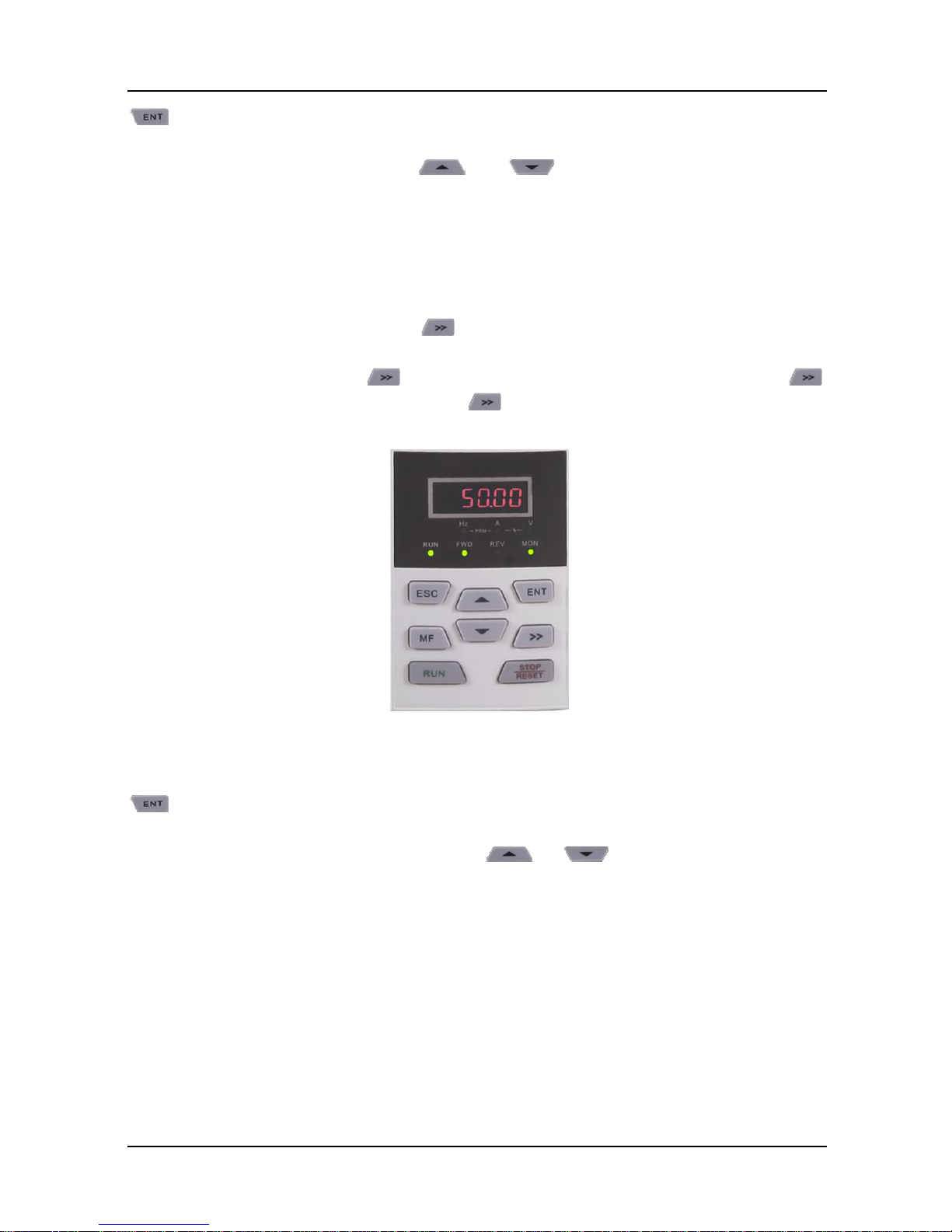
4.1 Operation of Control Panel
As a human-machine interface, control panel is the main part for the drive to receive command
and display parameters.
Fig. 4-1 Control panel
4.1.1 Key Functions on Control Panel
On the control panel there are 8 keys whose functions are as shown in Table 4-1.
Table 4-1 Key functions on control panel
Symbol
Key name
Meaning
Enter key
1) Parameter edition enter
2) Confirmation of parameter settings
3) Confirmation of MF key function
Escape key
1) Return function
2) Invalid parameter edit value
Increase key
1) Increase of selected bit of parameter value
2) Increase of selected bit of parameter value
3) Increase of set frequency
Decrease key
1) Decrease of selected bit of parameter
2) Decrease of selected bit of parameter value
3) Decrease of set frequency
Shift key
1) Selection of parameter bit
2) Selection of parameter value bit
3) Selection of stop/run status display parameter value
4) Fault status switches to parameter value display status
Run key
Run

GK600E User Manual Chapter 4 Operation and Run Instructions
- 41 -
Stop/reset key
1) Stop
2) Fault reset
Multi-function
key
See Table 4-2 " MF key function definition"
Table 4-2 MF key function definition
L0-00 set
value
Function of MF key
Meaning
0
Disabled
MF key disabled
1
Forward JOG
Forward JOG function
2
Reverse JOG
Reverse JOG function
3
Forward/Reverse
sw itch
Run direction forward and reverse switching
4
Emergency
STOP 1
Press to STOP, w ith ramp-down time b2-09
5
Emergency
STOP 2
Coast to stop, the drive cuts off output
6
Run command
setting mode
sw itch
Control panel control -> Terminal control ->
Communication control -> Control panel control, press
to confirm w ithin 5 seconds
4.1.2 Control Panel Indicators
Control panel is furnished w ith 7 indicators whose descriptions are as below
Table 4-3 Description of indicators
Indicator
Designation
Meaning
Hz
Frequency indicator
ON: currently displayed parameter value is run
frequency or the current parameter unit is
frequency
Flash: currently displayed parameter value is set
frequency
A
Current indicator
ON: currently displayed parameter value is current
V
Voltage indicator
ON: currently displayed parameter value is voltage
Hz+A
Run speed indicator
ON: currently displayed parameter value is run
speed
Flash: currently displayed parameter value is
setting speed
A+V
Percentage indicator
ON: currently displayed parameter value is a
percentage value
All OFF
No unit
No unit
MON
Run command setting
mode indicator
ON: Control panel
OFF: Terminal
Flash: Communication
RUN
Run status indicator
ON: Run

Chapter 4 Operation and Run Instructions GK600E User Manual
- 42 -
Indicator
Designation
Meaning
OFF: Stop
Flash: Stopping
FWD
Forward indicator
ON: If the drive in stop status, forward command
enabled. If the drive in run status, the drive is
running forward
Flash: Forward is being transferred to reverse
REV
Reverse indicator
ON: If the drive in stop status, reverse command
enabled. If the drive in run status, the drive is
running reversely.
Flash: Reverse is being transferred to forward
4.1.3 Control Panel Display Status
Control panel indicates eight types of status, STOP parameters display, Run parameters
display, Fault display, parameter number edition, parameter setting, Password authentication,
Direct frequency modification and Prompt message. The operation relating to these statuses
and the sw itching among these statuses is described as follows.
4.1.3.1 Display of STOP Parameters
The drive normally gets into STOP parameters display once run has been stopped. By default,
set frequency is displayed in such a status, and other parameters can be displayed through
setting of L1-02 parameters and the key. For example, when users need to check set
frequency as well as the values of bus voltage and AI1 value in stop status, set L1 -02=0013
(refer to setting method of parameters) and press the key to display the value of bus
voltage and then press again to display the value of AI1.
Fig. 4-2 Stop parameter display status (Displaying setting frequency – 50.00Hz)
Run status w ill be enabled immediately upon receipt of run command in stop status. Press
GK600E User Manual Chapter 4 Operation and Run Instructions
- 43 -
to get into parameter edit status (get into password authentication status if parameter
under password protection). Directly get into frequency modification status when receive
UP/DOWN command from terminal, or and pressing on control panel. Switch to
fault display status once a fault occurs or an alarm is given.
4.1.3.2 Run Parameter Display Status
In case there is no fault, the drive will get into run parameters display status upon receipt of run
command. Default display is run frequency, and other parameters can be displayed through
setting of L1-00 and L1-01 and press to shift. For example, in run status, when users
need to check bus voltage, motor speed, and input terminals status, please set L1-00= 0084
and L1-01= 0004, and press to shift to the display of bus voltage, then press
again to display motor speed, and then press to display input terminals state value.
Fig. 4-3 Run parameter display status (Displaying run frequency – 50.00Hz)
Stop status w ill be enabled immediately upon receipt of stop command in such a status. Press
to get into parameter edit status (get into password authentication status if parameter
under password protection). Directly get into frequency modification status when receiving
UP/DOWN command from terminal, or pressing or . Sw itch to fault alarm display
status once a fault occurs or an alarm is given.
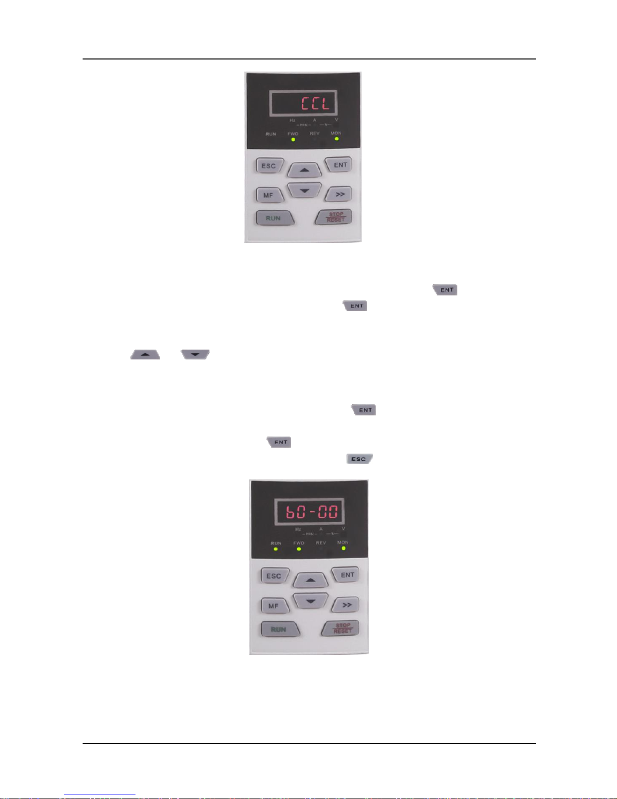
4.1.3.3 Fault Alarm Display Status
In case a fault occurs or an alarm is given, the drive will get into fault or alarm display status.
Chapter 4 Operation and Run Instructions GK600E User Manual
- 44 -
Fig. 4-4 Fault or alarm display status (CCL: Contactor act fault)
In such a status, the drive gets into stop status upon receipt of pressing , and would get
into parameter edit status when receiving pressing command again (if parameter is
under password protection, the drive would get into password authentication status). Directly
get into frequency modification status when receiving UP/DOWN command from terminal, or
pressing or .
4.1.3.4 Parameter Edit Status
Enter parameter edit status immediately upon pressing in STOP status, run parameters
display status, and direct frequency modification status. This status could also be entered upon
receipt of consecutive twice pressing in fault display status. The drive shall quit current
status and be previous status upon receipt of pressing .
Fig. 4-5 Parameter edit status
GK600E User Manual Chapter 4 Operation and Run Instructions
- 45 -
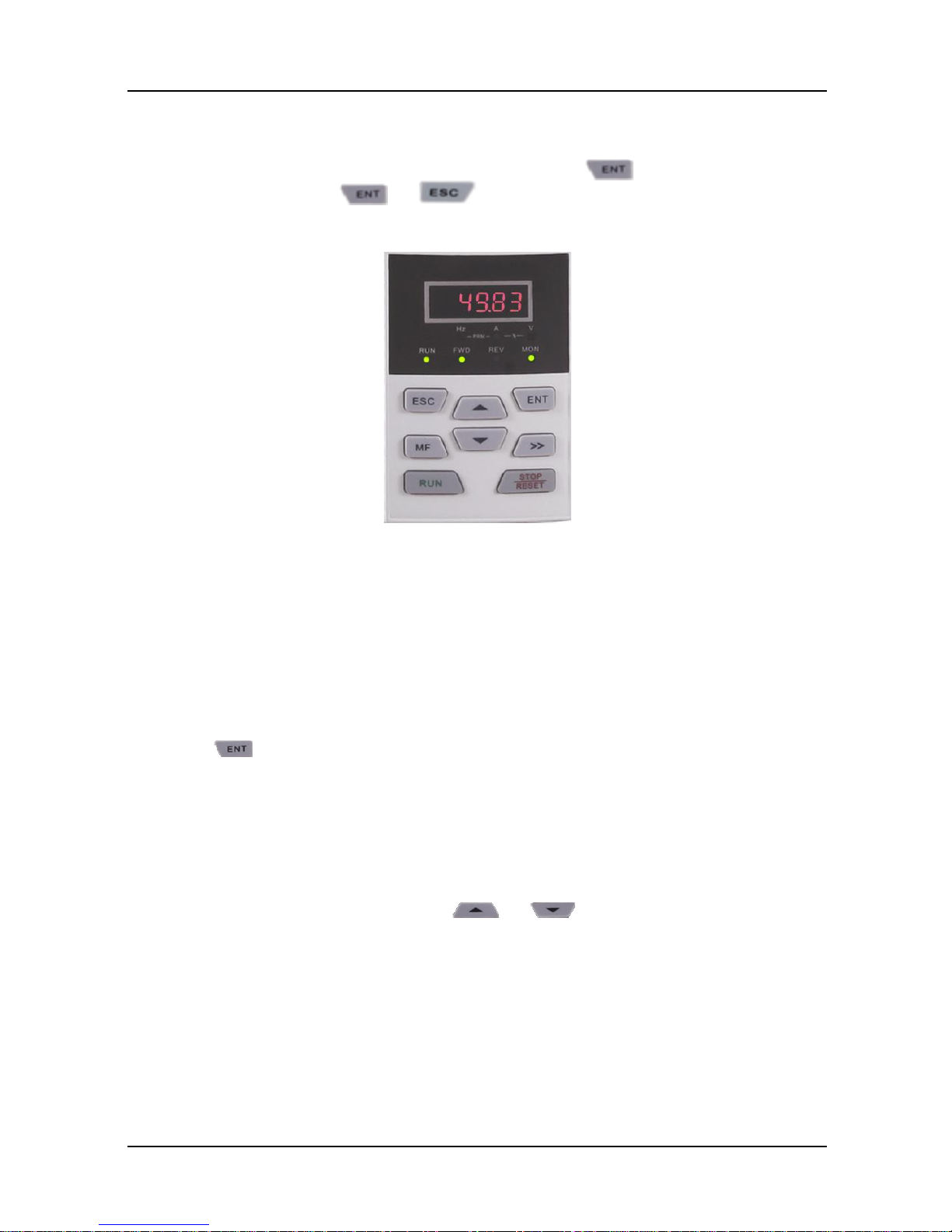
4.1.3.5 Parameter Value Setting Status
Enter parameter value setting status upon receipt of pressing when in parameter value
edit status. When pressing or command is received in such a state, escape
parameter edit status.
Fig. 4-6 Parameter value setting status (b0-02 is set to 49.83Hz)
4.1.3.6 Password Authentication Status
On condition that parameters are under password protection, users would have to go through
password authentication when they want to modify function code parameter value. Only A0-00
is visible in such a state.
Under password protection, the password authentication status will be first entered upon the receipt
of pressing in STOP parameter display status, run parameter display status, or direct
frequency modification status (refer to the setting method of parameters). It will enter parameter edit
status upon the completion of password authentication.
4.1.3.7 Direct Frequency Modification Status
In the status of STOP, fault or run, the drive will enter frequency modification status when
terminal UP/DOWN is enabled, or pressing or .

Chapter 4 Operation and Run Instructions GK600E User Manual
- 46 -
Fig. 4-7 Direct frequency modification status
4.1.3.8 Prompt Message Status
Prompt message status shall be displayed upon the completion of some operations. For
instance, the "bASIC" prompt message would be displayed upon the completion of parameter
initialization.
Fig. 4-8 Prompt message status
Prompt message characters and their meanings are shown as specified in Table 4-4.
Table 4-4 Prompt characters
Prompt
symbol
Meaning
Prompt
symbol
Meaning
bASIC
When A0-01 is set to 0
CPyb1
Backup parameter value
dISP1
When A0-01 is set to 1
LoAd
Parameter upload to
control panel
GK600E User Manual Chapter 4 Operation and Run Instructions
- 47 -
USEr
When A0-01 is set to 2
dnLd1
Parameter download from
control panel (motor
parameter excluded)
ndFLt
When A0-01 is set to 3
dnLd2
Parameter download from
control panel (motor
parameter included)
LoC-1
Control panel locked 1 (full locked)
P-SEt
Passw ord has been set
LoC-2
Control panel locked 2 (all locked
except RUN, STOP /RESET)
P-CLr
Passw ord cleared
LoC-3
Control panel locked 3
(all locked except STOP/RESET)
TUNE
Motor parameter
identification in process
LoC-4
Control panel locked 4
(all locked except shift )
LoU
Drive undervoltage
PrtCt
Control panel protection
CLr-F
Clear fault record
UnLoC
Control panel lock cleared
dEFt1
Restore to factory default
parameters (motor
parameter excluded)
rECy1
Read the backup parameter value to
parameter
dEFt2
Restore to factory default
parameters (motor
parameter included)
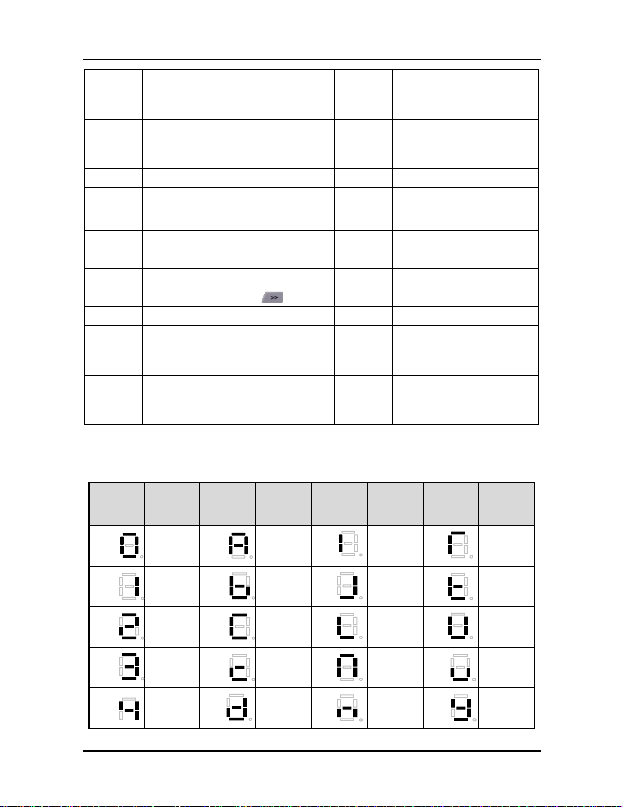
Table 4-5 shows meanings of the characters displayed on control panel.
Table 4-5 Meanings of displayed characters
Displayed
character
Character
Meaning
Displayed
character
Character
Meaning
Displayed
character
Character
Meaning
Displayed
character
Character
Meaning
0 A I T
1
b J t
2 C L U
3 c N v
4 d n y

Chapter 4 Operation and Run Instructions GK600E User Manual
- 48 -
Displayed
character
Character
Meaning
Displayed
character
Character
Meaning
Displayed
character
Character
Meaning
Displayed
character
Character
Meaning
5 E o
-
6
F P 8.
7 G
q .
8 H
r
9 h
S
4.1.4 Setting Method of Parameters
4.1.4.1 Parameter System
GK600E series drive parameter groups: A0, A1, b0, b2, C0, C4, d0, d2, E0, E1, F1, F6, H0, L0,
L1, U0, U1. Each parameter group contains a number of parameters. Parameters are identified
by the combination "parameter group character + parameter subgroup number + parameter
number". For instance, "F3-07" indicates the seventh parameter at subgroup 3, group F.
4.1.4.2 Parameter Display Structure
Parameters and the parameter values are subject to a two-tier structure. Parameters
correspond to first-tier display, while parameter values correspond to second-tier display.
First-tier display shown in Fig. 4-9:

GK600E User Manual Chapter 4 Operation and Run Instructions
- 49 -
Fig. 4-9 First-tier display of parameter
Second-tier display shown in Fig. 4-10:
Fig. 4-10 Second-tier display of parameter ("3" is the value of b0-00)
4.1.4.3 Example of Setting of Parameter
Parameter values are divided into decimal (DEC) and hexadecimal (HEX) values. When a
parameter value is expressed by a hexadecimal, all its bits are independent of each other
during edition and the range of value would be (0~F). Parameter value is composed of the unit,
tens place, hundreds and kilobit. Shift Key is used to select the bit to be changed, while
and are used to increase or decrease numerical value.
Example of parameter password setting
Setting of password (A0-00 is set to 1006)
1) In non-parameter edit status, it displays current parameter A0-00 when
pressing .
Chapter 4 Operation and Run Instructions GK600E User Manual
- 50 -
2) Press to display parameter value 0000 that belongs to A0-00;
3) Press for six times to change the rightmost digit "0" to "6";
4) Press to move the flashing digit to the leftmost bit;
5) Press once to change "0" in leftmost bit to "1";
6) Press to save the value of A0-00, then Control panel will switch to display the
next parameter A0-01;
7) Press to change A0-01 to A0-00;
8) Repeat steps 2) till 6). A0-01 w ill be displayed after control panel displaying P-SEt;
9) There are three methods for users to bring the password setting above into effect:
① Press + + simultaneously (PrtCt displayed), ②w on’t
operate control panel within 5 minutes, ③ restart the drive.
Flow chart of user password setting:
Fig. 4-11 Flow chart of user password setting
ATTENTION:
User's password is successfully set when step 8 finished, but will not take effect until the
completion of step 9.
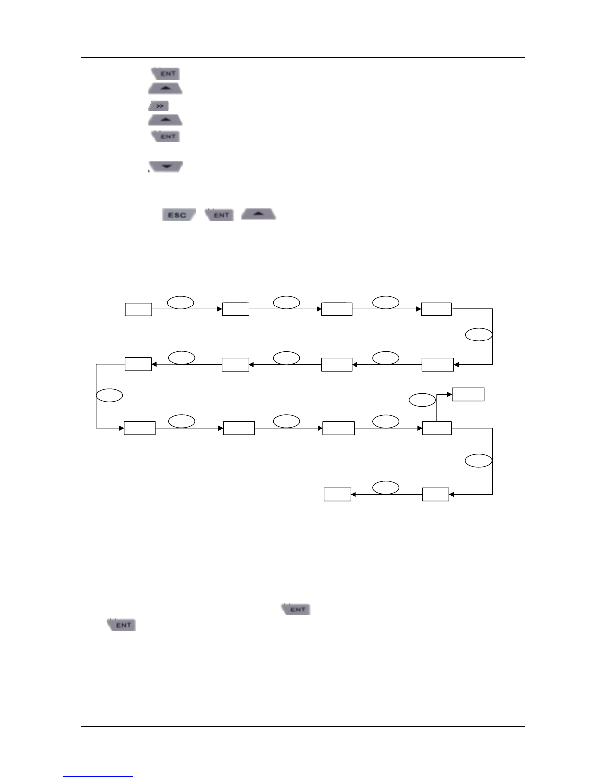
Password authentication
In non-parameter edit status, press to enter first-tier display A0-00, then press
to enter second-tier display 0.0.0.0. Control panel will implement the display of
other parameters only w hen correct password entered.
Clear password
After successful password authentication, it w ill access password setting code A0-00.
Passw ord can be cleared by writing value 0000 into A0-00 twice.
放弃修改
50.00 50.00 0.0.0.60.0.0.0
A0-00
50.00
ENT
ENT
▲
>>
0.0.0.61.0.0.6A0-01
A0-00
ENT
▲
▼
ENT
0.0.0.0
0.0.0.6
0.0.0.6
1.0.0.6
A0-0150.00
A0-00
ESC
▲
>>▲
ENT
ESC
Escape modification
GK600E User Manual Chapter 4 Operation and Run Instructions
- 51 -
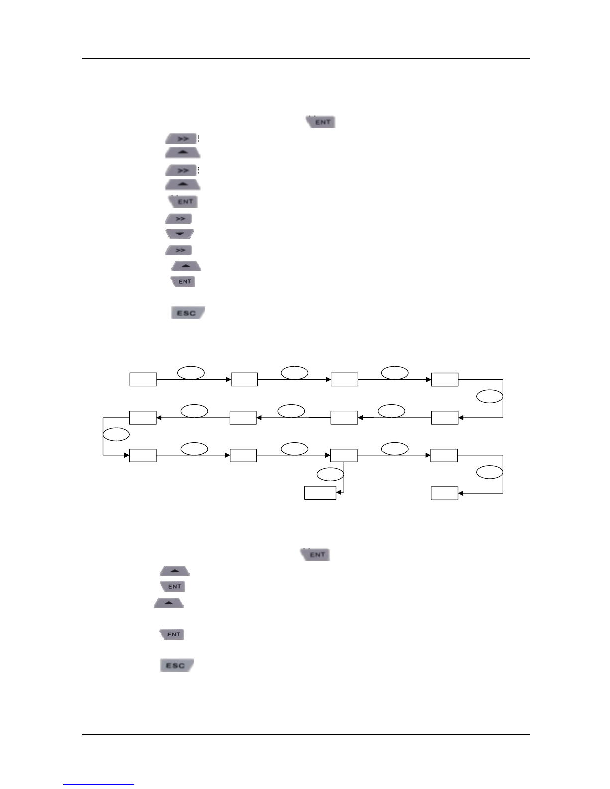
Example of parameter setting
Example 1: modify upper limit frequency from 600Hz to 50Hz (change b0-09 from
600.00 to 50.00)
1) In non-parameter edit status, press to display current parameter A0-00;
2) Press to move flashing digit to modification bit (A flashes);
3) Press once to change "A" to "b";
4) Press to move flashing to modification bit (0 in ones place flashing);
5) Press nine times to change "0" to "9";
6) Press to view the parameter value (600.00) of b0-09;
7) Press to move flashing digit to modification digit (6 flashing);
8) Press six times to change "6" to "0";
9) Press once to move flashing digit rightwards by one bit;
10) Press for five times to change "0" to "5";
11) Press to save the value (50.00) of b0-09. Then the control panel will
automatically switch to display the next function code (b0-10);
12) Press to exit parameter edit status.
Flow chart is shown below:
Fig. 4-12 Flow chart of upper limit frequency modification
Example 2: user parameter initialization
1) In non-parameter edit status, press to display current parameter A0-00;
2) Press three times to change "0" in the rightmost bit of A0-00 to "3";
3) Press to display parameter value 0 of A0-03;
4) Press once to change "0" to "2" or "3" ("2" motor parameter excluded, "3"
means motor parameter included);
5) Press to save the value of A0-03.Then control panel w ill automatically display
parameter A0-00;
6) Press to escape parameter edit status.
放弃修改
50.00
ENT
A0-00 A0-00
>>
b0-00
▲
>>
b0-00
b0-09
600.00600.00
000.00 000.00 050.00
b0-09
b0-10
50.00
▲
ENT
>>
▼
>> ▲
ESC
ENT
ESC
Escape modification

Chapter 4 Operation and Run Instructions GK600E User Manual
- 52 -
Flow chart is shown below:
Fig. 4-13 Flow chart of user parameter initialization
Example 3: setting method of hexadecimal parameter
Take L1-02 (LED STOP display parameter) for example, if LED control panel is required to
display: setting frequency, bus voltage, AI1, running linear speed, and setting linear speed.
Since all bits are independent of each other, the ones place, tens place, hundreds place and
thousands place should be set separately. Determine the binary numbers of each bit and then
convert the binary numbers into a hexadecimal number. See Table 4-6, the corresponding
relation between binary numbers and a hexadecimal number.
Table 4-6 Corresponding relation between binary and hexadecimal
Binary numbers
Hexadecimal
(LED bit display value)
BIT3
BIT2
BIT1
BIT0
0 0 0 0 0
0 0 0 1 1
0 0 1 0 2
0 0 1 1 3
0 1 0 0 4
0 1 0 1 5
0 1 1 0 6
0 1 1 1 7
1 0 0 0 8
1 0 0 1 9
1 0 1 0 A
1 0 1 1 B
1 1 0 0 C
1 1 0 1 D
1 1 1 0 E
1 1 1 1 F
Set the value in the ones place:
As shown in Fig. 4-14, "setting frequency" and "bus voltage" are respectively determined by
50.00
ENT
A0-00 A0-03 0
2或3
A0-0050.00
▲
ENT
▲
ENT
ESC
2 or 3
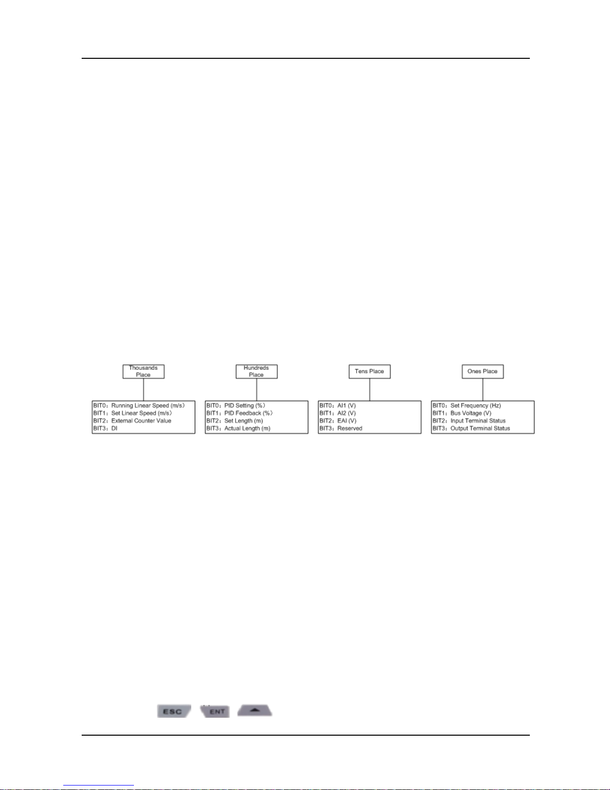
GK600E User Manual Chapter 4 Operation and Run Instructions
- 53 -
BIT0 and BIT1 in ones place of L1-02. If BIT0=1, setting frequency will be displayed. The bits
that correspond to the parameters which are not required to display shall be set to 0. Therefore,
the value in ones place should be 0011, corresponding to 3 in a hexadecimal number. Set the
ones place to 3.
Set the value in tens place:
As shown in Fig. 4-14, since it is required to display "AI1", the binary set value of tens place is
0001, corresponding to 1 in a hexadecimal number. Thus, bit of tens place shall be set to 1.
Set the value in hundreds place:
As shown in Fig. 4-14, the parameter required to display does not involve hundreds place, so
the hundreds place shall be set to zero.
Set thousands place:
As shown in Fig. 4-14, since required to display "running linear speed" and "setting linear
speed", the binary set value of thousands place shall be 0011 that corresponds to 3 in a
hexadecimal number.
To sum up, L1-02 should be set to 3013.
Fig. 4-14 Setting of hexadecimal parameter L1-02
Under parameter setting status, the parameter value cannot be modified if the value has no
flashing digit. Possible causes include:
1) The parameter cannot be modified, such as actual detection parameters, running recording
parameters, etc;
2) This parameter cannot be modified in run status but can be changed when motor stopped;
3) Parameter under protection. When parameter A0-02 is set to 1, parameters cannot be
modified as the parameter protection against misoperation enabled. To edit parameter in
such a circumstance, it is necessary to set A0-02 to 0 as first step.
4.1.4.4 Lock/Unlock Control Panel
Lock control panel
All or some keys of CONTROL PANEL can be locked by any of the follow ing three
methods. See the definition of parameter L0-01 for further information.
Method 1: set the parameter value of L0-01 to non-zero, then press
+ + simultaneously.
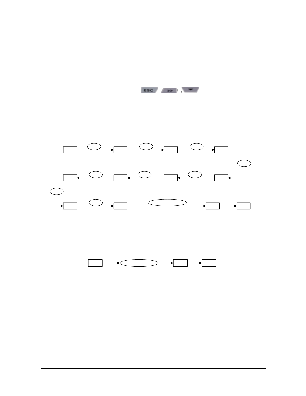
Chapter 4 Operation and Run Instructions GK600E User Manual
- 54 -
Method 2: do not operate CONTROL PANEL w ithin five minutes after L0-01 is set to
non-zero.
Method 3: cut the power off and then apply power on after L0-01 parameter is set to
non-zero.
Refer to flow chart 4-15 for locking CONTROL PANEL.
Unlock control panel
To unlock the control panel, press + + simultaneously. Unlocking
won’t change the value of parameter L0-01. In other words, the control panel will be locked
again if the condition of locking control panel is fulfilled. To unlock the control panel
completely, L0-01 value must be modified to 0 after unlocking.
Refer to flow chart 4- 16 of unlocking control panel
Fig. 4-15 Flow chart of locking control panel
Fig. 4-16 Flow chart of unlocking control panel
ESC+ENT+▲
50.00
ENT
A0-00
>>
A 0-00
▲
L0-00
>>
L0-00
▲
L0-0101
L0-02 50.00
ENT
▲
ENT
ESC
PrtCt
50.00
50.00 Ulock 50.00
ESC+>>+
▲

GK600E User Manual Chapter 5 Elevator Dedicated Parameters
- 55 -
Chapter 5 Elevator Dedicated Parameters
GK600E series are dedicated for open-loop elevator application. The electrical installation,
commissioning and the maintenance of the device should therefore only be carried out by
qualified personnel.
5.1 Standard Wiring
For open loop control, standard w iring of elevator dedicated drives is as shown as below
Fig. 5-1 Elevator standard wiring
M
DC Reactor
Jumper
Braking
Resistor
Motor
Ground
R/L1
S/L2
T/L3
U/T1
V/T2
W/T3
Power
Supply
Ground
++
1
2/B1
B2
UPS
1-phase
220VAC
Three-phase
Power Supply
380V-460V
50/60Hz
+24V
PLC
X1
X2
X3
X4
X5
X6
COM
Enable
Run Fwd
Run Rev
Multi-speed sel 1
Multi-speed sel 2
Multi-speed sel 3
RA
RB
RC
+24V
Y1
Y2/DO
COM
+10V
AI1
GND
Relay Output
250V AC/3A
30V DC/3A
Open Collector Output 1
Open Collector Output 2
High-speed Pulse Output
Option Board Interface
CN2
GK600E
Jumper
Analog In Reference
Voltage
POT
OFFONV
IVI
485 AI1 AO1
AI2
GND
485 MODBUS
Communication
485+
485-
AO1
GND
GND
Paired
Cable
Shielded
Cable
Analog In
DC: 0~10V/0~20mA
Analog In
DC:-10V~10V
Analog Out
DC:0~10V/0~20mA
Control Panel
-
KM1
KM4
KM1
KM2
KM3
Safety Contacts
X7 (On Option Board)
Emergency Speed
Relay Output
(On Option Board)
250V AC/3A
30V DC/3A
RA
RB
RC
KM2 KM3

Chapter 5 Elevator Dedicated Parameters GK600E User Manual
- 56 -
5.2 Elevator Sequence
Timing diagrams of the elevator sequence are shown as Fig. 5-2
1 0
1 2
3 4 5 6 7
1. F6.13 Cont close delay (default: 0.50s)
2. F6.05 Magnet time (default: 0.30s )
3. F6.06 Brake open delay (default: 0.20s )
4. F6.08 Smooth start delay (default: 0.00s)
5. F6.11 Brake waiting time (default: 0.40)
6. F6.12 Brake close delay (default: 0.10)
7. F6.14 Cont open delay (default: 0.50)
Fig. X.X – Standard lift sequence
Note: Lift sequence will not start if there is no current flowing on any of the motor windings during
the initial injection of DC-current. The minimum amount of current necessary to release the
mechanical brake and initiate the lift sequence is defined by F6.03 Brake open current. When
the parameter value is set to 0, current check is disabled, and the lift sequence will start even
if the motor is disconnected from the drive.
If using DC injection brake start, for start comfortability, DC injection brake time b1-09 should
be no less than F6.05 + F6.06. For stop comfortability, DC injection brake time b1-16 should
be no less than F6.11+F6.12
Enable
Run Fwd
Or
Run Rev
Freq Sel 1...4
Actual Speed
(motor speed)
Output current
(Inverter)
Run contactor
DC braking
(motor)
Lift start
Lift start
b2.03
b2.15
b2.01
b2.16 b2.17
b2.02
b2.18
F6.15
F6.17/F6.18
F6.16
Fig. 5-2 Standard elevator sequence
GK600E User Manual Chapter 5 Elevator Dedicated Parameters
- 57 -
5.3 Startup Manual
In order to make drive installation and commissioning easier, all the parameters needed for
standard setup are gathered in the STARTUP menu. The list of parameters in startup menu of
the lift version follows:
Group A0: System Parameters
A0-00
Setting of user password
Range: 0~FFFF
Factory default:
0000
Setting of password:
A non-zero four-digital number could be set as a user password by entering this password into
A0-00 and pressing ENT key to confirm once, then reenter and reconfirm it once again within
10 seconds. Once this password has been successfully set, the word "P-SEt" w ould be
displayed. The password setting will take effect as long as there is no operation on control
panel within 5 minutes, or cutting the power off and power up again.
Change password:
Access A0-00 after entering the original four-digit password (at this point, A0-00 displays 0000)
and set the new password following the above-noted procedure.
Password clearance:
Access A0-00 after entering the original four-digit password (at this point, A0-00 displays 0000),
enter 0000 twice and press ENT key to make confirmation. In this way, password is
successfully cleared and the w ord "P-CLr" is displayed.
A0-01
Parameter display
Range: 0~3
Factory default:
0
This parameter sets the display/hide of parameters.
0: Display all parameters (A1-20~A1-21 parameter display/hide is valid)
1: Only display A0-00 and A0-01
2: Only display A0-00, A0-01 and user-defined A1-00~A1-19
3: Only display A0-00, A0-01, and the parameters different from factory defaults.
A0-02
Parameter protection
Range: 0~1
Factory default:
0
0: All parameter programming allowed
1: Only A0-00 and this parameter programming allowed
When this parameter is set to 1, all parameters other than A0-00 and A0-02 are not allowed to
modify. Set A0-02 to 0 before the modification of other parameters.
Chapter 5 Elevator Dedicated Parameters GK600E User Manual
- 58 -
A0-03
Parameter restoration
Range: 0~4
Factory default:
0
0: No operation
1: Clear fault record
When this parameter is set to 1, all fault record of Group U1 will be cleared.
2: Restore all parameters to factory default (excluding motor parameters)
3: Restore all parameters to factory default (including motor parameters)
4: Restore all parameters to backup parameters
Group b1 Start/Stop Control
b1-00
Run command
Range: 0~2
Factory default: 1
This parameter sets run command source. Run commands include "RUN, STOP, FWD and
REV", etc. Please keep the default to terminal control if there is no peculiar requirement for lift
application.
0: Control panel control
Control run command through RUN, STOP/RESET and MF keys on control panel (set
multifunction key MF to JOG by L0-00). Refer to Chapter 4 about the operation of control
panel.
1: Terminal control
Control run command via DI terminals. Perform FORWARD and REVERSE by DI terminals.
The control mode is two-wire mode and three-wire mode programmable. See Group C0 for
details of designation and wiring regulation of DI terminals.
2: Communication control
Master device is able to control run command through built-in RS485 serial communication
interface of drive. Refer to parameters Group H0 and appendix for further information about
programming.
b1-01
Binding of run command
and frequency set
Range: 000 ~ AAA
Factory default:
090
This parameter defines the bundled combination of three run command sources and frequency
set with the purpose of facilitating simultaneous switching. For example: frequency setting AI1
(ones place of b1-01 is set to 3) bundled w ith control panel control, while the frequency setting
X6/DI pulse input (ten's place of b1-01 is set to 6) bundled w ith terminal control. In such a case,
when run command is controlled by control panel, frequency setting would be AI1, w hile when
run command is controlled via terminals, frequency setting will be automatically switched to
X6/DI pulse input.
Ones place: frequency setting bundled under control panel control
GK600E User Manual Chapter 5 Elevator Dedicated Parameters
- 59 -
0: No binding
1: Digital setting (b0-02) + ∧/∨ adjustment on control panel
2: Digital setting (b0-02) + terminal UP/DOWN adjustment
3: Analog input AI1
4:Aanalog input AI2
5: Analog input EAI (on IO option board)
6: X6/DI pulse input
7: Process PID output
8: Simple PLC
9: Multi-step frequency
A: Communication input
Refer to parameter b0-01 for details regarding above-mentioned sources of frequency setting.
Tens place: frequency setting bundled under terminal control (same as ones place)
Hundreds place: frequency setting bundled under communication control (same as ones
place)
ATTENTION:
Different run command sources can be bundled with the same frequency setting source. The
priority of frequency setting sources bundled with run command overrides Group b0.
b1-02
Run direction
Range: 0~1
Factory default: 0
This parameter applies to run command controlled by control panel, and disabled under
terminal and communication control.
0: Forward
1: Reverse
b1-05
Start method
Range: 0~3
Factory default: 1
This parameter takes effect during the process of transition from stop status to run status.
0: From start frequency
When drive starts to run from stop status, it starts from start frequency (b1-06) and keeps this
frequency for a period of time set by b1-07, and then accelerated to set frequency in
accordance with the Accel method and time.
1: DC injection brake start
To make the motor stop completely before a new start, the drive will perform DC braking w ith
a certain period of time, as specified by b1-08 and b1-09, then start from start frequency
(b1-06), keeping a period of time as specified by b1-07, and then Accelerate to set frequency.
2: Flying start 1
3: Flying start 2
b1-06
Start frequency
Range: 0.00Hz ~ upper limit
frequency
Factory default:
0.00Hz

Chapter 5 Elevator Dedicated Parameters GK600E User Manual
- 60 -
b1-07
Holding time of start
frequency
Range: 0.0s ~ 3600.0s
Factory default:
0.0s
Start frequency is initial output frequency of drive start from stop status. Start frequency holding
time is the continuous run time w ith start frequency. After this holding time, the drive w ill
Accelerate to set frequency. Usually appropriate start frequency and holding time assure the
starting torque of heavy-duty load.
Provided that set frequency is lower than start frequency, drive output frequency is 0 Hz. Start
frequency and start frequency holding time take effect at the moment of motor start, as well as the
transfer between forward and reverse. Accel time at Group b2 excludes the holding time of start
frequency.
b1-08
DC brake start current
Range: 0.0%~100.0%
Factory default:
80.0%
b1-09
DC brake start time
Range: 0.00s~30.00s
Factory default:
0.50s
When the motor is started by the method "DC injection brake start", it is essential to set these
two parameters. 100% corresponds to rated current of drive. If brake time is set to 0.0s, DC
brake at start is disabled. Using DC injection brake start, for start comfortability, DC injection
brake time b1-09 should be no less than F6.05 + F6.06.
b1-13
Stop method
Range: 0~2
Factory default: 2
0: Ramp to stop
Upon the receipt of stop command, drive gradually decreases output frequency according to
the set Decel time, and stop w hen frequency attains 0.
1: Coast to stop
Upon the receipt of stop command, drive will immediately lock the output and the motor will
stop with its mechanical inertia.
2: Ramp to stop + DC brake
Upon the receipt of stop command, drive w ill decrease output frequency in accordance with
the rate of Decel time setting. Once the output frequency attains set value of b1-14, DC
braking will be enabled, and the drive will stop after the finish of DC braking.
b1-14
Start frequency of DC
brake stop
Range: 0.00Hz ~ upper limit
frequency
Factory default:
0.20Hz
b1-15
DC injection brake
current at stop
Range: 0.0%~100.0%
Factory default:
80.0%
b1-16
DC injection brake time
at stop
Range: 0.00s~60.00s
Factory default:
0.50s
During the process “ramp to stop + DC brake", DC brake would be started when output
GK600E User Manual Chapter 5 Elevator Dedicated Parameters
- 61 -
frequency attains the set value of b1-14. b1-15 defines brake level, in amps, applied to the
motor. 100% corresponds to rated current of drive. b1-16 sets the duration that DC brake
current w orks when b1-13 is set to 2. In case b1-16 is set to 0.0s, DC brake shall be disabled.
Using DC injection brake stop, for stop comfortability, DC injection brake time b1-16 should be
no less than F6.11 + F6.12.
b1-18
Dynamic brake
Range: 0~1
Factory default: 1
0: Disabled
1: Enabled
When dynamic brake is enabled, the electric energy generated during Decel shall be
converted into heat energy consumed by brake resistor, so as to attain rapid Decel. For all
the drives dedicated for elevator and lift (3.7kW-30kW), the brake choppers are inbuilt as
default. Brake resistors with the recommended values need to be installed outside of the
drives.
b1-19
Dynamic brake
threshold voltage
Range: 650V~750V
Factory default:
680V
When b1-18 is set to 1 (default), and drive bus voltage attains the value of b1-19, dynamic
brake shall perform. The energy shall be rapidly consumed through brake resistor. This value is
used to regulate the brake effect.
Group b2 Accel/Decel Parameters
b2-01
S-curve linear acc time
Range: 0.00s~600.00s
Factory default:
3.5s
b2-02
S-curve linear dec time
Range: 0.00s~600.00s
Factory default:
2.00s
b2-03
Smooth start acc time
Range: 0.00s~600.00s
Factory default:
30.00s
These parameters b2-01~b2-08 set the rate of Accel/Decel for speed increase/decrease.
Maximum Freq (b0-08) / Accel time X = Accel Rate X
Maximum Freq (b0-08) / Decel time X = Decel Rate X
As the formula sets forth above, Accel time means required time for drive to Accelerate to
maximum frequency b0-08 from zero frequency, while Decel time refers to the time required for
drive to Decelerate to zero frequency from maximum frequency b0-08.
Chapter 5 Elevator Dedicated Parameters GK600E User Manual
- 62 -
b2-12
Accel/Decel curve
Range: 0~5
Factory default: 5
0: Linear Accel/Decel
1: Broken-line Accel/Decel
2: S-curve Accel/Decel A
3: S-curve Accel/Decel B
4: S-curve Accel/Decel C
5: Elevator dedicated S-curve
b2-15
S-curve acc start time
Range: 0.00s~60.00s
Factory default: 1.00s
b2-16
S-curve acc end time
Range: 0.00s~60.00s
Factory default: 1.00s
b2-17
S-curve dec start time
Range: 0.00s~60.00s
Factory default: 1.00s
b2-18
S-curve dec end time
Range: 0.00s~60.00s
Factory default: 1.00s
Group C0 Digital Input
C0-01
Function of terminal X1 (Default: Enable)
Range: 0~99
Factory default: 71
C0-02
Function of terminal X2 (Default: FWD)
Range: 0~99
Factory default: 3
C0-03
Function of terminal X3 (Default: REV)
Range: 0~99
Factory default: 4
C0-04
Function of terminal X4 (Default: MSS1)
Range: 0~99
Factory default: 15
C0-05
Function of terminal X5 (Default: MSS2)
Range: 0~99
Factory default: 16
C0-06
Function of terminal X6 (Default: MSS3)
Range: 0~99
Factory default: 17
C0-07
Function of terminal X7
(on IO option) (Default: Emergency)
Range: 0~99
Factory default: 18
When grid power supply is lost, elevator controller is switched to UPS power supply and output
emergency signal to the drive. Immediately after receiving this emergency signal, the drive will
go into emergency mode. GK600E supports UPS power supply 220V single phase input or
380V three phase input. In emergency mode, the drive will run at emergency frequency set by
F1-17 (default: 5Hz), and run via acceleration time b2-07 or deceleration time b2-08. As default,
the digital input X7 at option board is used as emergency signal input (C0-07 =18). If users
would like to use other terminal input like X5 as emergency signal input, corresponding
parameter C0-05 have to be set to 18: emergency.
Following are the meanings of different parameter values. For more please refer to the
complete parameter list in Chapter 6.
3: Run forward (FWD) 4: Run reverse (REV) 5: Three-w ire control 6: Run suspended
7: External stop 8: Emergency stop 15:Multi-speed selector 1 16:Multi-speed selector 2
17: Multi-speed selector 3 18: Emergency Speed 22: External fault input
23: Fault reset (RESET) 71: Enable
GK600E User Manual Chapter 5 Elevator Dedicated Parameters
- 63 -
Group C1 Digital Output
In elevator application, a relay output is often used to control run contactor, another relay output
controls the brake, while a digital output reports the fault. As default configuration and setting,
GK600E has a relay output at its control board to control the brake, and a relay output at its
option board EPC-TM1 to control the run contactor.
C1-00
Y1 output function
Range: 0~99
Factory default: 14
C1-01
Y2/DO output function
(w hen used as Y2)
Range: 0~99
Factory default: 0
C1-02
Control board relay
output function
Range: 0~99
Factory default: 27
C1-03
Option board relay
output function
Range: 0~99
Factory default: 35
14: Fault output
27: Brake control
35: RUN contactor control
For more information of different parameter values, please refer to the complete parameter list
in Chapter 6.
Group d0 Motor Parameters
d0-00
Motor type
Range: 0~1
Factory default: 1
0: Ordinary motor
1: Variable frequency motor
The major difference between ordinary motor and variable frequency motor depends on the
handling of motor overload protection. Under low speed run, ordinary motor has poor heat
dissipation, so motor overload protection shall be derated at low speed. Since fan-based heat
dissipation of variable frequency motor is not affected by motor speed, low-speed overload
protection is not necessarily derated. Therefore, please set d0-00 to 0 when driving ordinary
asynchronous motor so as to protect the motor reliably.
d0-01
Motor pow er rating
Range:
0.4kW~6553.5kW
Factory default:
model dependent
d0-02
Motor rated voltage
Range: 0V~480V
Factory default: 380V
d0-03
Motor rated current
Range: 0.0A~6553.5A
Factory default:
model dependent
d0-04
Motor rated freq
Range: 0.00Hz~upper
limit frequency
Factory default:
50.00Hz
Chapter 5 Elevator Dedicated Parameters GK600E User Manual
- 64 -
d0-05
Motor pole
Range: 1~80
Factory default: 4
d0-06
Motor rated speed
Range: 0~65535 r/min
Factory default:
model dependent
Above-noted motor parameters must be correctly set according to motor nameplate. Please
select the motor that suits the power class of the drive, otherwise the control performance of
the drive w ill drop dramatically, or cause elevator safety problems when the drive power rating
is smaller than the motor power ratings.
d0-07
Motor stator resistance R1
Range: 0.001Ω~65.535Ω
Factory default:
model dependent
d0-08
Motor leakage inductance
L1
Range: 0.1mH~6553.5mH
Factory default:
model dependent
d0-09
Motor rotor resistance R2
Range: 0.001Ω~65.535Ω
Factory default:
model dependent
d0-10
Motor mutual inductance
L2
Range: 0.1mH~6553.5mH
Factory default:
model dependent
d0-11
Motor no-load current
Range: 0.0A~6553.5A
Factory default:
model dependent
d0-12
Motor flux w eakening coeff
1
Range: 0.0000~1.0000
Factory default:
model dependent
d0-13
Motor flux w eakening coeff
2
Range: 0.0000~1.0000
Factory default:
model dependent
d0-14
Motor flux w eakening coeff
3
Range: 0.0000~1.0000
Factory default:
model dependent
The drive needs above-noted parameters to control its matching motor. If the parameters of
motor is known, just write the actual value into d0-07~d0-14 correspondingly.
After the motor tune (usually motor tune is not needed for GK600E), above-noted parameters
are automatically updated and saved. Parameters d0-07~d0-09 are obtained through static
motor tune, and parameters d0-07~d0-14 are obtained through rotary motor run. If
above-noted parameters are unknown and it is not allowed to perform motor tune, please input
the parameters manually by referring to parameters of like motors.
If motor power rating d0-01 is changed, d0-02~d0-14 will be automatically restored to default
settings of the standard motor.
d0-22
Motor auto-tune
Range: 0~2
Factory default: 0
Parameters for controlling the motor performance are automatically obtained through auto-tune,
and the result will be automatically saved upon the completion of auto-tune. Be sure to

GK600E User Manual Chapter 5 Elevator Dedicated Parameters
- 65 -
correctly input motor parameters d0-01~d0-06 before motor tune.
0: No motor auto-tune
1: Static motor auto-tune
Static motor auto-tune applies to the cases where rotary auto-tune cannot be favorably
performed due to the fact that it is impossible to disengage the motor from its load. After
d0-22 is set to 1 and confirmed, press the key RUN to start static auto-tune. d0-22 will be
restored to 0 upon the successful completion of auto-tune. In this way, parameters
d0-07~d0-09 are obtained.
2: Rotary motor auto-tune
To perform rotary auto-tune, it is essential to disengage the motor from its load. Auto-tune is
prohibited when motor is loaded. After d0-22 is set to 2 and confirmed, press RUN to perform
Rotary auto-tune, upon the completion of which, the motor would accelerate to a fixed
frequency in the set ramp-up time, maintaining a period of time, and then stop by ramp down
according to the set ramp dow n time. In this w ay, the auto-tune comes to an end, and d0-22
will be restored to 0. Parameters d0-07~d0-14 have be obtained after the successful
completion of rotary auto-tune. To perform rotary auto-tune, please set appropriate ramp-up
and ramp-dow n time (i.e. Accel/Decel time. If overcurrent or overvoltage fault occurs during
auto-tune, please prolong Accel/Decel time accordingly.)
ATTENTION:
To consider the comfort of lift, GTAKE adopts multi-step V/f control technology rather than
vector control, and therefore motor atuto-tune is not required usually. However, if users still
would like to have motor auto-tune, please only perform static tune and first b1-00 should be
set to 0 (keypad control). After auto-tune is successfully done, please restore b1-00 to 1
(terminal control).
The motor run contactor must be closed during tuning procedure in order to allow drive output
current to flow into the motor. Either hard-wire the RUN contactor closed during tuning
procedure, or connects the dedicated output of the drive to the RUN contactor. Please make
sure the motor is in a stationary state before the tuning, or tuning cannot be performed normally.
Control panel displays "TUNE" and RUN indicator light is on during tuning. RUN indicator light
is off upon the completion of tuning. Once tuning fails, the fault code "tUN" shall be displayed.
Group d1 Motor V/f Control Parameters
Set control parameters in Group d1 when motor 1 is selected as current load motor on which
V/f control is performed.
d1-00
V/f curve setting
Range: 0~8
Factory default: 1
Set the relation between output voltage and output frequency of the drive when motor is
under V/f control.
0: Linear V/f
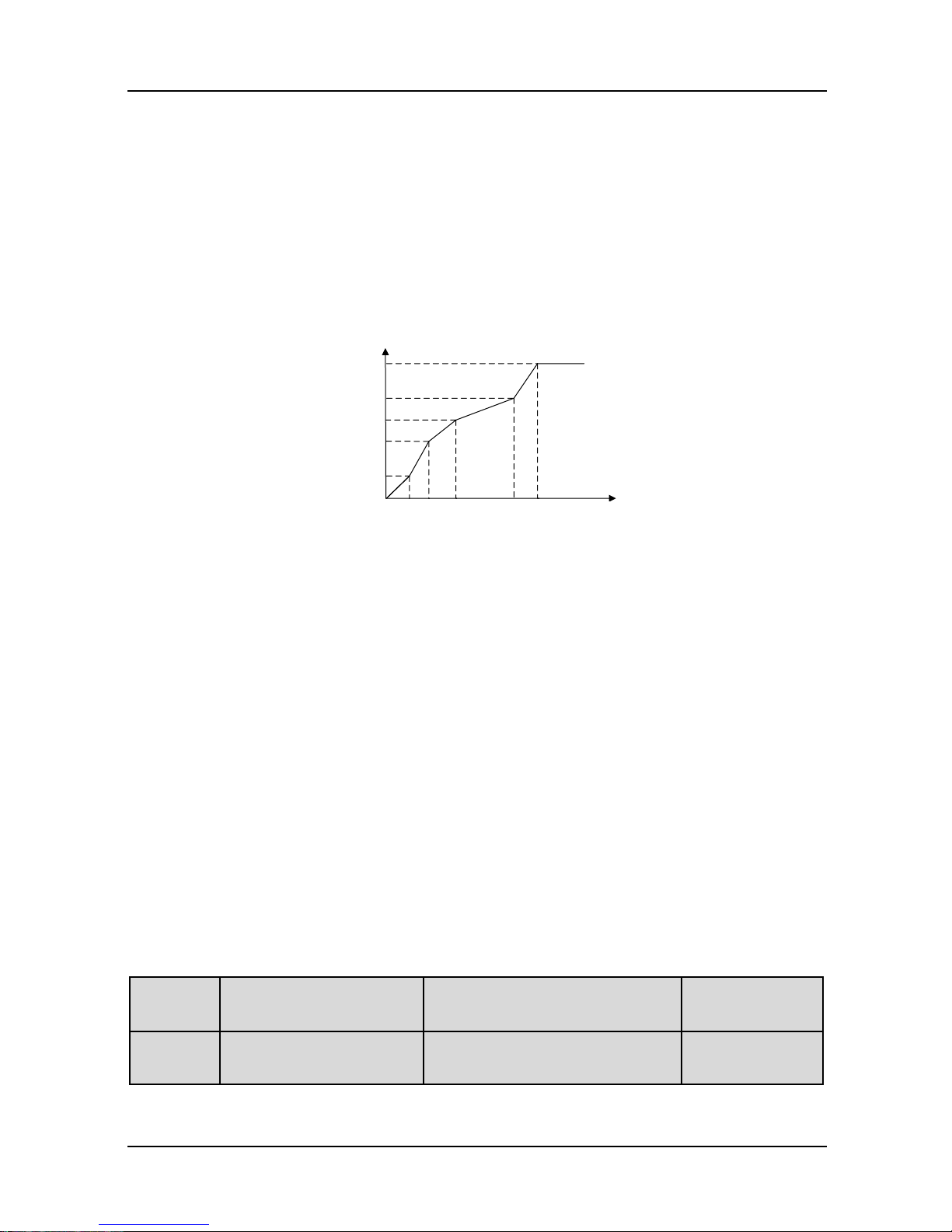
Chapter 5 Elevator Dedicated Parameters GK600E User Manual
- 66 -
Applies to general constant-torque load. When drive output frequency is 0, output voltage will
be 0, while when output frequency is rated frequency of motor, the output voltage would be
rated voltage of motor.
1: Broken line V/f (determined by d1-01~d1-08)
Applies to elevator, spin drier, centrifuge, industrial washing machine and other special loads.
When drive output frequency is 0, output voltage will be 0, while when output frequency is
rated frequency of motor, the output voltage would be rated voltage of motor. What is
different is this pattern can set 4 inflection points by d1-01~d1-08. See Fig. 5-3.
Fig. 5-3 User-defined multi-stage V/f curve
V0, V1, V2, V3 and f0, f1, f2 and f3 in the figure are voltage value and frequency value set by
parameters d1-01~d1-08.
2: 1.2nd power
3: 1.4th power
4: 1.6th power
5: 1.8th power
6: 2.0th power
Parameter values 2~6 apply to torque-dropped loads such as fans and water pumps. See
Fig. 6-42.
7: V/f separated pattern 1
Output frequency and output voltage can be set separately. Frequency is set by the method
as stated in Group b0. Output voltage is set by d1-18. See d1-18 for details. This mode
applies to variable-frequency power supply or torque motor control etc.
8: V/f separated pattern 2
Determine a certain voltage by linear V/f mode, and then multiply this voltage by the
proportion set by d1-18 to obtain drive output voltage. See d1-18 for details.
d1-01
V/f frequency value f3
Range: 0.00Hz~rated frequency
of motor
Factory default:
50.00Hz
d1-02
V/f voltage value V3
Range: 0.0%~100.0%
Factory default:
100.0%
输出电压(V)
输出频率(Hz)
f00 f1 f2 f3
电机额定频率
V0
V1
V2
V3
电机额定电压
Output voltage (V)
Rated voltage of
motor
Output frequency (Hz)
Rated frequency of motor
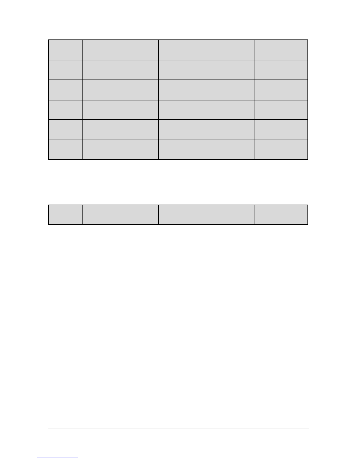
GK600E User Manual Chapter 5 Elevator Dedicated Parameters
- 67 -
d1-03
V/f frequency value f2
Range: d1-05~d1-01
Factory default:
15.00Hz
d1-04
V/f voltage value V2
Range: 0.0%~100.0%
Factory default:
35.0%
d1-05
V/f frequency value f1
Range: d1-07~d1-03
Factory default:
3.00Hz
d1-06
V/f voltage value V1
Range: 0.0%~100.0%
Factory default:
10.0%
d1-07
V/f frequency value f0
Range: 0.00Hz~d1-05
Factory default:
0.00Hz
d1-08
V/f voltage value V0
Range: 0.0%~100.0%
Factory default:
4.0 %
d1-01~d1-08 is used for multi-stage V/f mode. Voltage value 100% corresponds to rated
voltage of motor. Please suitably set the values of frequency and voltage at knees on the basis
of characteristics of motor and load. Improper setting may rise output current even burn the
motor.
d1-09
Torque boost
Range: 0.0%~30.0%
Factory default:
0.0%
Under V/f pattern, output voltage at low frequency can be compensated by this parameter,
improving the torque output. 0.0% corresponds to automatic torque boost, and drive output
voltage is automatically compensated via detection of load current. Automatic torque boost is
valid only for linear V/f pattern.
100% of torque boost corresponds to rated voltage of motor. A non-zero value means the
output voltage rises on the basis of V/f curve and this takes effect at parameter values 0~6 of
d1-00. It is suggested this parameter value be gradually increased from zero until the starting
requirement is met. Boost value is not suggested to be set to a relatively big one, as it is likely
to bring about a bigger drive current and higher motor temperature.
Torque boost diagram is shown as Fig. 5-4:

Chapter 5 Elevator Dedicated Parameters GK600E User Manual
- 68 -
Fig. 5-4
Group E0 Enhanced Function
E0-00
Switching FREQ
Range: 0.7~16.0kHz
Model dependent
With lower switching frequency, output current of the drive produces higher harmonics, motor
loss increases, and temperature and motor noise rise, but drive temperature, drive leakage
current, and drive interference to external devices are lower or less.
With higher switching frequency, drive temperature will rise, drive leakage current is bigger, and
drive interference to external devices is bigger. However, motor loss and noise will be lower,
and motor temperature will drop.
The table below specifies the setting range and factory default of PWM switching frequency of
the drives at different power ratings:
Table 5-1
Pow er rating of the drives
Setting Range
Factory Default
≤15kW
0.7k~16k
8k
18.5kW~30kW
0.7k~10k
4k
Tips for PWM sw itching frequency setting:
1) When the motor line is too long, reduce switching frequency.
2) When torque at low speed is unstable, reduce sw itching frequency.
3) If the drive produces severe interference to surrounding equipment, reduce switching
frequency.
4) Leakage current of the drive is big, reduce switching frequency.
5) Drive temperature rise is relatively high, reduce switching frequency.
6) Motor temperature rise is relatively high, increase sw itching frequency.
0
输出频率(Hz)
输出电压(V)
电机额定频率
电机额定电压
提升量
Output frequency (Hz)
Output voltage (V)
Rated voltage of motor
Boost value
Rated frequency of motor
GK600E User Manual Chapter 5 Elevator Dedicated Parameters
- 69 -
7) Motor noise is relatively big, increase switching frequency.
Group E1 Protection Parameters
E1-00
Overvoltage stall
Range: 0~1
Factory default: 0
0: Prohibited
1: Allowed
When the motor is decelerating with a high-inertia load or short-term regenerative braking
occurs during the run, the energy feedback to the drive may raise DC bus voltage, and thus
resulting in overvoltage protection.
When this parameter value is set to 1, the drive will detect its bus voltage and compare with
parameter set by E1-01. If the bus voltage exceeds value of E1-01, drive output frequency
shall be adjusted instantaneously and the deceleration time shall be automatically prolonged,
to maintain the stability of DC bus voltage. Set this parameter to 0 if frequency fluctuation or
Decel time prolonging is not allowed.
E1-01
Overvoltage stall
protection voltage
Range: 120%~150%
Factory default:
135%
This value is a percentage compared to standard DC bus voltage.
E1-03
Overload alarm
Range: 000~111
Factory default:
100
Ones place: detection option
0: Always detect
Overload alarm w orks all the time during drive running.
1: Detect at constant speed only
Overload pre-alarm only works during constant-speed running of inverter.
Tens place: compared w ith
0: motor rated current
Compared object is the rated current relative to motor, and display "oL2" when the alarm is
given under this setting
1: drive rated current
Compared object is the rated current of drive, and display "oL1" when the alarm is given
under this setting.
Hundreds place: drive action
0: Alarm but run continued
When drive output current exceeds the level set by E1-04 and the lasting time attains
parameter value of E1-05, the drive will alarm but continue its running.
1: Alarm and coast to stop
Chapter 5 Elevator Dedicated Parameters GK600E User Manual
- 70 -
When drive output current exceeds the level set by E1-04 and the lasting time attains
parameter value of E1-05, the drive will display overload fault and coast to stop.
E1-04
Overload alarm threshold
Range: 20.0%~200.0%
Factory default:
120.0%
When tens place of E1-03 is set to 0, this parameter value is a percentage compared to rated
current of motor. When tens place of E1-03 is set to 1, this parameter value is a percentage
compared w ith rated current of drive.
E1-05
Overload alarm activation
time
Range: 0.1s~60.0s
Factory default:
7.0s
Sets the lasting time that overload alarm is activated when output current of drive is bigger than
the threshold set by E1-04.
E1-12
Cooling fan control
Range: 0~1
Factory default: 0
0: Auto run
The fans run all the time during the running. Determine if the fans continue to run or stop
according to module temperature after stop.
1: Always run after power up
The fans run all the time after applying power to the drive.
E1-13
Drive overheat alarm
threshold
Range: 0.0℃~100.0℃
Factory default:
80.0℃
This parameter sets the threshold of drive overheat alarm.
Group F1 Multi-step Frequency
Multi-speed references can be defined as high speed, leveling speed, inspection speed
according to different requirements.
F1-02
Multi-step frequency 0
Lower limit frequency ~ upper
limit frequency
Factory default:
0.00 Hz
F1-03
Multi-step frequency 1
Lower limit frequency ~ upper
limit frequency
Factory default:
0.00 Hz
F1-04
Multi-step frequency 2
Lower limit frequency ~ upper
limit frequency
Factory default:
0.00 Hz
F1-05
Multi-step frequency 3
Lower limit frequency ~ upper
limit frequency
Factory default:
0.00 Hz
F1-06
Multi-step frequency 4
Lower limit frequency ~ upper
limit frequency
Factory default:
0.00 Hz

GK600E User Manual Chapter 5 Elevator Dedicated Parameters
- 71 -
F1-07
Multi-step frequency 5
Lower limit frequency ~ upper
limit frequency
Factory default:
0.00 Hz
F1-08
Multi-step frequency 6
Lower limit frequency ~ upper
limit frequency
Factory default:
0.00 Hz
F1-09
Multi-step frequency 7
Lower limit frequency ~ upper
limit frequency
Factory default:
0.00 Hz
Multi-speed frequency 0 till multi-speed frequency 7 sets frequency references (Hz) of the drive. The
selection of any of the above reference is performed by the dedicated selectors (Multi-speed
Sel 1 to 3).
Multi-speed Sel
3
Multi-speed Sel
2
Multi-speed Sel
1
Frequency reference
OFF
OFF
OFF
Multi-speed frequency 0(F1-02)
OFF
OFF
ON
Multi-speed frequency 1(F1-03)
OFF
ON
OFF
Multi-speed frequency 2(F1-04)
OFF
ON
ON
Multi-speed frequency 3(F1-05)
ON
OFF
OFF
Multi-speed frequency 4(F1-06)
ON
OFF
ON
Multi-speed frequency 5(F1-07)
ON
ON
OFF
Multi-speed frequency 6(F1-08)
ON
ON
ON
Multi-speed frequency 7(F1-09)
GK600E have following default setting:
X1 for Enable C0-01=71
X2 for Fw d C0-02=3
X3 for Rev C0-03=4
X4 for multi-speed sel 1 C0-04=15
X5 for multi-speed sel 2 C0-05=16
X6 for multi-speed sel 3 C0-06=17
Group F6: Elevator Control Mode
F6-00
Lift control mode
Range: 0000~1111
Factory default:
0101
Ones place: Brake control
0: Disabled
1: Enabled
Tens place: Logic of elevator and motor run direction
0: Positive logic
1: Negative logic
Hundred place : Motor run enable signal

Chapter 5 Elevator Dedicated Parameters GK600E User Manual
- 72 -
0: Disabled
1.Enabled
Thousands place: Leveling compensation
0: Leveling mode 1
1: Leveling mode 2
2: Commissioning mode
ATTENTION:
During commissioning, w hen the lift goes up, and control panel light FWD is on, please keep
tens place to the default: positive logic, and vice versa. This is a must to program the respective
parameters for lift up or lift down correspondingly. Thousands place are for GTAKE engineers
only w hen it is required at some peculiar cases, users are not suggested to change thousands
place to non-zero before sufficient communication w ith GTAKE engineers.
F6-02
Brake open frequency
Range: 0.00Hz~10.00Hz
Factory default:
0.00Hz
If start method is not DC injection brake start, when drive outpt frequency exceeds brake open
frequency set by F6-02, and drive output current exceeds brake open current set by F6-03, wait
magnet time set by F6.05, brake is released.
F6-03
Brake open current
Range: 0.0%~200.0%
Factory default:
0.0%
Sets the minimum amount of current necessary to release the mechanical brake and initiate the
lift sequence. When the parameter value is set to 0, current check is disabled, and the lift
sequence will start even if the motor is disconnected from the drive.
F6-05
Magnet time
Range: 0.00s~10.00s
Factory default:
0.3s
Sets duration of the initial magnetizing of the motor w ith DC injection.
F6-06
Brake open delay
Range: 0.00s~10.00s
Factory default:
0.2s
Sets time delay between the open command and effective opening of the mechanical brake.
F6-07
Smooth start frequency
Range: 0.00Hz~b0-09
Factory default:
2.00HZ
Frequency reference used during the smooth start procedure.
F6-08
Smooth start delay
Range: 0.00s~10.00s
Factory default:
0.00s

GK600E User Manual Chapter 5 Elevator Dedicated Parameters
- 73 -
F6-09
Brake close frequency
Range: 0.00Hz~10.00Hz
Factory default:
0.2Hz
F6-11
Brake waiting time
Range: 0.00s-10.00s
Factory default:
0.4s
Duration of the stopping phase, after the speed has fallen below the zero threshold (F6-09) or
DC brake stop/start frequency (b1-14). During this phase, the inverter can either output a DC
current (default), or maintain a low frequency, in order to compensate for the slip, as
programmed by F6-09.
F6-12
Brake close delay
Range: 0.00s-10.00s
Factory default:
0.1s
Sets time delay between the close command and the effective engagement of the mechanical
brake.
F6-13
Contactor close delay
Range: 0.00s-10.00s
Factory default:
0.5s
Sets time delay for safe closing of the run contactor.
F6-14
Contactor open delay
Range: 0.00s-10.00s
Factory default:
0.5s
Sets time delay between the open command and the effective opening of the run contactor.
F6-15
Leveling start s-curve time
Range: 0.00s-60.00s
Factory default:
0.00s
F6-16
Leveling end s-curve time
Range: 0.00s-60.00s
Factory default:
0.00s
F6-17
Lift-up leveling linear dec
time
Range: 0.00s-60.00s
Factory default:
5.00s
F6-18
Lift-down leveling linear
dec time
Range: 0.00s-60.00s
Factory default:
5.00s
F6-19
Lift-up slip compensation
Range: 0.0%-400.0%
Factory default:
150.0%
F6-19 Sets the amount of slip compensation (% of rated slip, calculated from nameplates) to
improve lift going up leveling when required.
F6-20
Lift-down slip
compensation
Range: 0.0%-400.0%
Factory default:
60.0%
F6-20 sets the amount of slip compensation (% of rated slip, calculated from nameplates) to
improve lift going downing leveling w hen required.

Chapter 5 Elevator Dedicated Parameters GK600E User Manual
- 74 -
F6-22
Leveling frequency
Range: 0.00Hz-400.00Hz
Factory default:
5.00Hz
Note: this parameter value must be set to the same as the leveling frequency as defined by
multi-speed sel 1 to 3
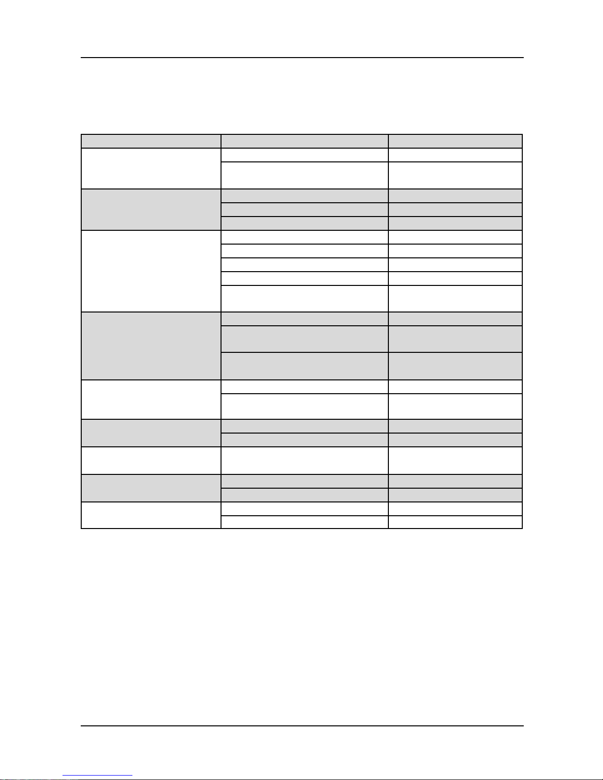
GK600E User Manual Chapter 6 List of Parameters
- 75 -
Chapter 6 List of Parameters
GK600E parameter groups are listed below:
Category
Parameter group
Reference page
Group A: system
parameters and parameter
management
A0: system parameters
P76
A1: user-defined display
parameters
P77
Group b: Run parameter
setting
b0: frequency setting
P78
b1: start/stop control
P79
b2: Accel/Decel parameters
P81
Group C: input and output
terminals
C0: digital input
P82
C1: digital output
P85
C2: analog and pulse input
P86
C3: analog and pulse output
P88
C4: automatic correction of
analog input
P89
Group d: motor and control
parameters
d0: parameters of motor 1
P90
d1: V/f control parameters of
motor 1
P91
d2: vector control parameters of
motor 1
P92
Group E: enhanced
function and protection
parameters
E0: enhanced function
P93
E1: protection parameters
P95
Group F: application
F1: multi-step frequency
P97
F6: Lift dedicated parameters
P98
Group H: communication
parameters
H0: MODBUS communication
parameters
P98
Group L: keys and display
of control panel
L0: keys of control panel
P99
L1: control panel display setting
P100
Group U: monitoring
U0: status monitoring
P102
U1: history fault
P105
ATTENTION:
Change attribute:
"△" means the value of this parameter can be modified in stop and run status of drive;
"×" means the value of this parameter cannot be modified when drive is running;
"◎" means this parameter is a measured value that cannot be modified;
Factory default: The value w hen restored to factory default. Neither measured
parameter value nor recorded value w ill be restored.
Scope: the scope of setting and display of parameter values

Chapter 6 List of Parameters GK600E User Manual
- 76 -
Parameter
Designation
Scope
Factory
default
Attr
Group A: System Parameters and Parameter Management
Group A0: System Parameters
A0-00
Setting of user password
0~FFFF
0000
△
A0-01
Parameter display
0: Display all parameters
1: Only display A0-00 and A0-01
2: Only display A0-00, A0-01 and
user-defined A1-00~A1-19
3: Only display A0-00, A0-01, and the
parameters different from factory
default
0
△
A0-02
Parameter protection
0: All parameter programming
allowed
1: Only A0-00 and this parameter
programming allowed
0
×
A0-03
Parameter restoration
0: No operation
1: Clear fault record
2: Restore all parameters to factory
default (excluding motor
parameters)
3: Restore all parameters to factory
default (including motor
parameters)
4: Restore all parameters to backup
parameters
0
×
A0-04
Parameter backup
0: No operation
1: Backup all parameters
0
×
A0-05
Parameter copy
0: No operation
1: Parameter copied to control panel
2: Parameter copied (excluding motor
parameters) to control board
3: Parameter copied (including motor
parameters) to control board
0
×
A0-06
Type of drive
0: Type G (applicable to
constant-torque load)
1: Type L (applicable to light-duty
load)
0
×
A0-07
Pow er supply type of
SMPS
0: Supplied by DC bus voltage of
drive main circuit
1: Supplied independently
0
◎
A0-08
Motor 1 / motor 2 selection
0: Motor 1
1: Motor 2
0
×
A0-09
Reserved
Reserved
Reserved
◎

GK600E User Manual Chapter 6 List of Parameters
- 77 -
Parameter
Designation
Scope
Factory
default
Attr
Group A1: User-defined Display Parameters
A1-00
User-defined display
parameter 1
Setting range of thousands place:
A, b, C, d, E, F, H, L, U
Setting range of hundreds place: 0~9
Setting range of tens place: 0~9
Setting range of ones place: 0~9
A0-00
×
A1-01
User-defined display
parameter 2
A0-00
×
A1-02
User-defined display
parameter 3
A0-00
×
A1-03
User-defined display
parameter 4
A0-00
×
A1-04
User-defined display
parameter 5
A0-00
×
A1-05
User-defined display
parameter 6
A0-00
×
A1-06
User-defined display
parameter 7
A0-00
×
A1-07
User-defined display
parameter 8
A0-00
×
A1-08
User-defined display
parameter 9
A0-00
×
A1-09
User-defined display
parameter 10
A0-00
×
A1-10
User-defined display
parameter 11
A0-00
×
A1-11
User-defined display
parameter 12
A0-00
×
A1-12
User-defined display
parameter 13
A0-00
×
A1-13
User-defined display
parameter 14
A0-00
×
A1-14
User-defined display
parameter 15
A0-00
×
A1-15
User-defined display
parameter 16
A0-00
×
A1-16
User-defined display
parameter 17
A0-00
×
A1-17
User-defined display
parameter 18
A0-00
×
A1-18
User-defined display
parameter 19
A0-00
×
A1-19
User-defined display
parameter 20
A0-00
×
Chapter 6 List of Parameters GK600E User Manual
- 78 -
Parameter
Designation
Scope
Factory
default
Attr
A1-20
Parameter group
display/hide setting 1
0~FFFF
FFFF
×
A1-21
Parameter group
display/hide setting 2
0~FFFF
FFFF
×
Group b Run Parameter Setting
Group b0 Frequency Setting
b0-00
FREQ set mode
0: Master FREQ set
1: Master & auxiliary computation
result
2: Switch between master and
auxiliary set
3: Switch between master FREQ set,
and master & auxiliary computation
result
4: Switch between auxiliary FREQ
set, and master & auxiliary
computation result
0
×
b0-01
Master FREQ set
0: Digital setting (b0-02) + ∧ /∨
adjustment on control panel
1: Digital setting (b0-02) + terminal
UP/DOWN adjustment
2: Analog input AI1
3: Analog input AI2
4: Analog input EAI (on IO option)
5: X6/DI pulse input
6: Process PID output
7: PLC
8: Multi-step speed
9: Communication
0
×
b0-02
Master FREQ digital setting
Lower limit freq ~ upper limit freq
50.00Hz
△
b0-03
Auxiliary FREQ set
0: No setting
1: Digital setting (b0-04) + ∧/∨
adjustment on control panel
2: Digital setting (b0-04) + terminal
UP/DOWN adjustment
3: Analog input AI1
4: Analog input AI2
5: Analog input EAI (on IO option
board)
6: X6/DI pulse input
7: Process PID output
8: PLC
0
×

GK600E User Manual Chapter 6 List of Parameters
- 79 -
Parameter
Designation
Scope
Factory
default
Attr
9: Multi-step speed
10: Communication
b0-04
Auxiliary FREQ digital
setting
Lower limit FREQ ~ upper limit FREQ
0.00Hz
△
b0-05
Auxiliary FREQ range
0: Relative to maximum FREQ
1: Relative to master FREQ
0
×
b0-06
Auxiliary FREQ coeff
0.0%~100.0%
100.0%
×
b0-07
Computation of master and
auxiliary FREQ
0: Master + auxiliary
1: Master - auxiliary
2: Max {master, auxiliary}
3: Min {master, auxiliary}
0
×
b0-08
Maximum FREQ
Upper limit FREQ ~600.00Hz
50.00Hz
×
b0-09
Upper limit FREQ
Lower limit FREQ ~ maximum FREQ
50.00Hz
×
b0-10
Lower limit FREQ
0.00Hz~upper limit FREQ
0.00Hz
×
b0-11
Operation when set FREQ
lower than lower limit
FREQ
0: Run at lower limit FREQ
1: Run at 0 Hz
2: Stop
0
×
b0-12
Time-delay of stop when
set FREQ lower than lower
limit FREQ
0.0s ~ 6553.5s
0.0s
×
b0-13
Lower limit of skip FREQ
band 1
0.00Hz~upper limit FREQ
0.00Hz
×
b0-14
Upper limit of skip FREQ
band 1
0.00Hz~upper limit FREQ
0.00Hz
×
b0-15
Lower limit of skip FREQ
band 2
0.00Hz~upper limit FREQ
0.00Hz
×
b0-16
Upper limit of skip FREQ
band 2
0.00Hz~upper limit FREQ
0.00Hz
×
b0-17
Lower limit of skip FREQ
band 3
0.00Hz~upper limit FREQ
0.00Hz
×
b0-18
Upper limit of skip FREQ
band 3
0.00Hz~upper limit FREQ
0.00Hz
×
b0-19
Jog FREQ
0.00Hz~upper limit FREQ
5.00Hz
△
Group b1 Start/Stop Control
b1-00
Run command
0: Control panel control
1: Terminal control
2: Communication control
1
×

Chapter 6 List of Parameters GK600E User Manual
- 80 -
Parameter
Designation
Scope
Factory
default
Attr
b1-01
Binding of run command
and frequency set
Ones place: frequency set bundled
under control panel control:
0: No binding
1: Digital setting (b0-02) + ∧/∨
adjustment on control panel
2: Digital setting (b0-02) + terminal
UP/DOWN adjustment
3: Analog input AI1
4: Analog input AI2
5: Analog input EAI (on IO option
board)
6: X6/DI pulse input
7: Process PID output
8: Simple PLC
9: Multi-step FREQ
A: Communication input
Tens place: FREQ set bundled under
terminal control (same as ones place)
Hundreds place: FREQ set bundled
under communication control (same
as ones place)
090
×
b1-02
Run direction
0: Forward
1: Reverse
0
△
b1-03
Reverse disabled
0: Reverse enabled
1: Reverse disabled
0
×
b1-04
Dead time between forward
and reverse
0.0s~3600.0s
0.0s
△
b1-05
Start method
0: From start FREQ
1: DC braking start
2: Flying start 1
3: Flying start 2
1
×
b1-06
Start FREQ
0.00Hz~upper limit FREQ
0.00Hz
×
b1-07
Holding time of start FREQ
0.0s~3600.0s
0.0s
△
b1-08
DC braking current at start
0.0%~200.0%
80.0%
△
b1-09
DC braking time at start
0.00s~30.00s
0.50s
△
b1-10
Flying start 1 current
0.0~200.0%
100.0%
×
b1-11
Flying start 1 Decel time
0.1s~20.0s
2.0s
×
b1-12
Flying start 1 adjustment
coeff
20.0%~100.0%
100.0%
×
b1-13
Stop method
0: Ramp to stop
1: Coast to stop
2
×
GK600E User Manual Chapter 6 List of Parameters
- 81 -
Parameter
Designation
Scope
Factory
default
Attr
2: Ramp to stop + DC brake
b1-14
Start FREQ of DC brake
stop
0.00Hz~upper limit FREQ
0.20Hz
×
b1-15
DC brake current
0.0%~200.0%
80.0%
△
b1-16
DC brake time
0.00s~30.00s
0.50s
△
b1-17
Overexcitation brake
0: Enabled for all
1: Enabled except for deceleration
2: Disabled
1
×
b1-18
Dynamic brake
0: Disabled
1: Enabled
1
×
b1-19
Dynamic brake threshold
voltage
500V~750V
680V
×
b1-20
Auto restart when power up
again after pow er loss
0: Disabled
1: Enabled
0 × b1-21
Time delay of auto restart
when power up again
0.0s~10.0s
0.0s
△
Group b2 Accel/Decel Parameters
b2-00
Accel/Decel time resolution
0:0.01s
1:0.1s
2:1s
0
×
b2-01
S-curve linear acc time
0s~600.00s/6000.0s/60000s
3.50s
△
b2-02
S-curve linear dec time
0s~600.00s/6000.0s/60000s
2.00s
△
b2-03
Smooth start acc time
0s~600.00s/6000.0s/60000s
30.00s
△
b2-04
Decel time 2
0s~600.00s/6000.0s/60000s
6.00s
△
b2-05
Accel time 3
0s~600.00s/6000.0s/60000s
6.00s
△
b2-06
Decel time 3
0s~600.00s/6000.0s/60000s
6.00s
△
b2-07
Accel time 4
0s~600.00s/6000.0s/60000s
4.00s
△
b2-08
Decel time 4
0s~600.00s/6000.0s/60000s
2.00s
△
b2-09
Decel time for emergency
stop
0s~600.00s/6000.0s/60000s
6.00s
△
b2-10
Jog Accel time
0s~600.00s/6000.0s/60000s
6.00s
△
b2-11
Jog Decel time
0s~600.00s/6000.0s/60000s
6.00s
△
b2-12
Accel/Decel curve
0: Linear Accel/Decel
1: Broken-line Accel/Decel
2: S-curve Accel/Decel A
3: S-curve Accel/Decel B
4: S-curve Accel/Decel C
5: Elevator S-curve
5
×
b2-13
Accel time sw itching FREQ
of broken-line Accel/Decel
0.00Hz~upper limit FREQ
0.00Hz
△

Chapter 6 List of Parameters GK600E User Manual
- 82 -
Parameter
Designation
Scope
Factory
default
Attr
b2-14
Decel time switching FREQ
of broken-line Accel/Decel
0.00Hz~upper limit FREQ
0.00Hz
△
b2-15
S-curve acc start time
0.00s~60.00s (S-curve A)
1.00s
△
b2-16
S-curve acc end time
0.00s~60.00s (S-curve A)
1.00s
△
b2-17
S-curve dec start time
0.00s~60.00s (S-curve A)
1.00s
△
b2-18
S-curve dec end time
0.00s~60.00s (S-curve A)
1.00s
△
b2-19
Proportion of Accel S-curve
first segment
0.0%~100.0% (S-curve B)
20.0%
△
b2-20
Proportion of Accel S-curve
last segment
0.0%~100.0% (S-curve B)
20.0%
△
b2-21
Proportion of Decel S-curve
first segment
0.0%~100.0% (S-curve B)
20.0%
△
b2-22
Proportion of Decel S-curve
last segment
0.0%~100.0% (S-curve B)
20.0%
△
Group C Input and Output Terminals
Group C0 Digital Input
C0-00
Enabled condition of run
command terminals w hen
power up
0: Trigger edge detected + ON
detected
1: ON detected
0
×
C0-01
Function of terminal X1
0: No function
1: JOG forward
2: JOG reverse
3: Run forw ard (FWD)
4: Run reverse (REV)
5: Three-wire control
6: Run suspended
7: External stop
8: Emergency stop
9: Stop command + DC brake
10: DC brake stop
11: Coast to stop
12: Terminal UP
13: Terminal DOWN
14: Clear UP/DOWN (including ∧/∨
key) adjustment
15: Multi-step FREQ terminal 1
16: Multi-step FREQ terminal 2
17: Multi-step FREQ terminal 3
18: Lift emergency
19: Accel/Decel time determinant 1
20: Accel/Decel time determinant 2
21: Accel/Decel disabled(ramp stop
71
×
C0-02
Function of terminal X2
3
×
C0-03
Function of terminal X3
4
×
C0-04
Function of terminal X4
15
×
C0-05
Function of terminal X5
16
×
C0-06
Function of terminal X6/DI
17
×
C0-07
Function of terminal X7
(on IO option board)
18
×
C0-08
Function of terminal AI1
(Digital enabled)
0
×
C0-09
Function of terminal AI2
(Digital enabled)
0
×
C0-10
Function of terminal EAI
(Digital enabled) (on IO
0
×

GK600E User Manual Chapter 6 List of Parameters
- 83 -
Parameter
Designation
Scope
Factory
default
Attr
option board)
not inclusive)
22: External fault input
23: Fault reset (RESET)
24: Pulse input (valid only for X6/DI)
25: Motor 1/2 sw itchover
26: Reserved
27: Run command switched to control
panel control
28: Run command switched to
terminal control
29: Run command switched to
communication control
30: Frequency set mode shift
31: Master FREQ set switched to
digital setting b0-02
32: Auxiliary FREQ set switched to
digital setting b0-04
33: PID adjustment direction
34: PID paused
35: PID integration paused
36: PID parameter switch
37: Count input
38: Count clear
39: Length count
40: Length clear
41~62: Reserved
63: Simple PLC paused
64: Simple PLC disabled
65: Simple PLC stop memory clear
66: Start wobble frequency
67: Clear wobble frequency status
68: Run prohibited
69: DC brake in run
70: Analog input curve switching
71: Motor run enabled
71~99: Reserved
C0-11
Filtering time of digital input
terminal
0.000s~1.000s
0.010s
△
C0-12
Delay time of terminal X1
0.0s~3600.0s
0.0s
△
C0-13
Delay time of terminal X2
0.0s~3600.0s
0.0s
△
C0-14
Digital input terminal
enabled status setting 1
Ones place: X1
0: Positive logic
0000
×
Chapter 6 List of Parameters GK600E User Manual
- 84 -
Parameter
Designation
Scope
Factory
default
Attr
1: Negative logic
Tens place: X2 (same as ones place)
Hundreds place: X3 (same as ones
place)
Thousands place: X4 (same as ones
place)
C0-15
Digital input terminal
enabled status setting 2
Ones place: X5
0: Positive logic
1: Negative logic
Tens place: X6 (valid as ordinary
terminal, same as ones place)
Hundreds place: (on IO option board,
same as ones place)
Thousands place: reserved
0000
×
C0-16
Digital input terminal
enabled status setting 3
Ones place: AI1
0: Positive logic
1: Negative logic
Tens place: AI2 (same as ones place)
Hundreds place: EAI (on IO option
board, same as ones place)
Thousands place: reserved
0000
×
C0-17
Terminal UP/DOWN FREQ
adjustment action
Ones place: at stop
0: Cleared
1: Maintained
Tens place: on power loss
0: Cleared
1: Maintained
Hundreds place: integral function
0: No integral function
1: Integral function enabled
Thousands place: run direction
0: Changing run direction prohibited
1: Changing run direction allowed
0000
△
C0-18
Terminal UP/DOWN
frequency change step size
0.00Hz/s~100.00Hz/s
0.03 Hz/s
△
C0-19
FWD/REV terminal control
mode
0: Two-wire mode 1
1: Two-wire mode 2
2: Three-wire mode 1
3: Three-wire mode 2
0
×
C0-20
Option of virtual input
terminal
000~77F
0: Actual terminal in effect
000
×
GK600E User Manual Chapter 6 List of Parameters
- 85 -
Parameter
Designation
Scope
Factory
default
Attr
1: Virtual terminal in effect
Ones place: BIT0~BIT3: X1~X4
Tens place: BIT4~BIT6: X5~X6, EX
Hundreds place: BIT8~BIT10:
AI1~AI2, EAI (EX and EAI located at
IO option board)
C0-21
Enabled condition of run
command terminal after
fault reset (RESET)
0: Trigger edge detected + ON
detected
1: ON detected
0
△
Group C1 Digital Output
C1-00
Y1 output function
0: No output
1: Drive undervoltage
2: Drive run preparation completed
3: Drive is running
4: Drive running at 0Hz (there is no
output at stop)
5: Drive running at 0Hz (there is
output at stop)
6: Run direction
7: FREQ attained
8: Upper limit FREQ attained
9: Lower limit FREQ attained
10: Frequency detection FDT1
11: Frequency detection FDT2
12: Reserved
13: Torque limited
14: Fault output
15: Alarm output
16: Drive (motor) overloaded alarm
17: Drive overheat alarm
18: Zero current detection
19: X1
20: X2
21: Motor 1/ 2 indication
22: Set count value attained
23: Designated count value attained
24: Length attained
25: Consecutive run time attained
26: Accumulative run time attained
27: Brake control
28: Reserved
29: Reserved
14
△
C1-01
Y2/DO output function
(w hen used as Y2)
0
△
C1-02
Control board relay output
function
27
△
C1-03
Option board relay output
function
35
△
Chapter 6 List of Parameters GK600E User Manual
- 86 -
Parameter
Designation
Scope
Factory
default
Attr
30: PLC step completed
31: PLC cycle completed
32: Wobble frequency attains to
upper or lower limit frequency
33: Upper/lower limit of set FREQ
attained
34: Target FREQ attained (set by
C2-29)
35: Run contactor control
35~99: Reserved
C1-04
Y1 output time delay
0.0s~3600.0s
0.0s
△
C1-05
Y2 output time delay
0.0s~3600.0s
0.0s
△
C1-06
Control board relay output
time delay
0.0s~3600.0s
0.0s
△
C1-07
Option board relay output
time delay
0.0s~3600.0s
0.0s
△
C1-08
Enabled state of digital
output
Ones place: Y1
0: Positive logic
1: Negative logic
Tens place: Y2 (same as ones place)
Hundreds place: control board relay
output (same as ones place)
Thousands place: option board relay
output (same as ones place)
0000
×
C1-09
Detected object of FREQ
detection (FDT)
Ones place: FDT1 detected object
0: Speed set value (FREQ after
Accel/Decel)
1: Detected speed value
Tens place: FDT2 detected object
0: Speed set value (FREQ after
Accel/Decel)
1: Detected speed value
00
△
C1-10
FDT1 upper value
0.00Hz~maximum FREQ
50.00Hz
△
C1-11
FDT1 lower value
0.00Hz~maximum FREQ
49.00Hz
△
C1-12
FDT2 upper value
0.00Hz~maximum FREQ
25.00Hz
△
C1-13
FDT2 lower value
0.00Hz~maximum FREQ
24.00Hz
△
C1-14
Detection width of FREQ
attained
0.00Hz~maximum FREQ
2.50Hz
△
C1-15
Zero current detection
value
0.0%~50.0%
5.0%
△
C1-16
Zero current detection time
0.01s~50.00s
0.50s
△
Group C2 Analog and Pulse Input

GK600E User Manual Chapter 6 List of Parameters
- 87 -
Parameter
Designation
Scope
Factory
default
Attr
C2-00
Analog input curve
Ones place: AI1 input curve
0: Curve 1 (2 points)
1: Curve 2 (4 points)
2: Curve 3 (4 points)
3: Curve 2 and curve 3 sw itchover
Tens place: AI2 input curve
(same as ones place)
Hundreds place: EAI input curve
(same as ones place)
Thousands place: reserved
0000
×
C2-01
Curve 1 maximum input
Curve 1 minimum input ~ 110.0%
100.0%
△
C2-02
Corresponding set value of
curve 1 maximum input
-100.0%~100.0%
100.0%
△
C2-03
Curve 1 minimum input
-110.0% ~ curve 1 maximum input
0.0%
△
C2-04
Corresponding set value of
curve 1 minimum input
-100.0%~100.0%
0.0%
△
C2-05
Curve 2 maximum input
Range: input of curve 2 inflection
point A~110.0%
100.0%
△
C2-06
Set value corresponding to
curve 2 maximum input
Range: -100.0%~100.0%
100.0%
△
C2-07
Input of curve 2 inflection
point A
Input of curve 2 inflection point B ~
curve 2 maximum input
0.0%
△
C2-08
Set value Cor. to input of
curve 2 inflection point A
Range: -100.0%~100.0%
0.0%
△
C2-09
Input of curve 2 inflection
point B
Range: Curve 2 minimum input ~
Input of curve 2 inflection point A
0.0%
△
C2-10
Set value corresponding to
input of curve 2 inflection
point B
Range: -100.0%~100.0%
0.0%
△
C2-11
Curve 2 minimum input
Range: -110.0%~ input of curve 2
inflection point B
0.0%
△
C2-12
Set value corresponding to
curve 2 minimum input
Range: -100.0%~100.0%
0.0%
△
C2-13
Curve 3 maximum input
Range: input of curve 3 inflection
point A ~110.0%
100.0%
△
C2-14
Set value corresponding to
curve 3 maximum input
Range: -100.0%~100.0%
100.0%
△

Chapter 6 List of Parameters GK600E User Manual
- 88 -
Parameter
Designation
Scope
Factory
default
Attr
C2-15
Input of curve 3 inflection
point A
Range: input of curve 3 inflection
point B ~ curve 3 maximum input
0.0%
△
C2-16
Set value corresponding to
input of curve 3 inflection point A
Range: -100.0%~100.0%
0.0%
△
C2-17
Input of curve 3 inflection
point B
Range: curve 3 minimum input~ input
of curve 3 inflection point A
0.0%
△
C2-18
Set value corresponding to
input of curve 3 inflection point
B
Range: -100.0%~100.0%
0.0%
△
C2-19
Curve 3 minimum input
Range: -110.0%~ input of curve 3
inflection point B
0.0%
△
C2-20
Set value corresponding to
curve 3 minimum input
Range: -100.0%~100.0%
0.0%
△
C2-21
AI1 terminal filtering time
0.000s~10.000s
0.01s
△
C2-22
AI2 terminal filtering time
0.000s~10.000s
0.01s
△
C2-23
EAI terminal filtering time
(on IO option board)
0.000s~10.000s
0.01s
△
C2-24
DI maximum input
Range: C2-26~50.0kHz
50.0kHz
△
C2-25
Set value corresponding to
DI maximum input
Range: -100.0%~100.0%
100.0%
△
C2-26
DI minimum input
Range: 0.0kHz~C2-24
0.0kHz
△
C2-27
Set value corresponding to
DI minimum input
Range: -100.0%~100.0%
0.0%
△
C2-28
DI filtering time
0.000s~1.000s
0.001s
△
C2-29
Target FREQ
0.00Hz~upper limit FREQ
(enabled when C1-00 ~C1-03 is set
to 34 )
0.00Hz
△
Group C3 Analog and Pulse Output
C3-00
AO1 output function
0: No output
1: Set FREQ
2: Output FREQ
3: Output current (to drive rated)
4: Output torque (absolute value)
5: Output voltage
6: Output power
7: Bus voltage
8: Reserved
9: Torque current
10: Magnetic flux current
2
△
C3-01
EAO output function
(on IO option)
1
△
C3-02
Y2/DO output function
(w hen used as DO)
0
△
GK600E User Manual Chapter 6 List of Parameters
- 89 -
Parameter
Designation
Scope
Factory
default
Attr
11:AI1
12:AI2
13:EAI
14: Reserved
15:DI
16:Communication input percentage
17: Output FREQ before
compensation
18:Output current (relative to motor
rated current)
19:Output torque (direction hinted)
20:Set torque (direction hinted)
21~99: Reserved
C3-03
AO1 offset
-100.0%~100.0%
0.0%
×
C3-04
AO1 gain
-2.000~2.000
1.000
×
C3-05
AO1 filtering time
0.0s~10.0s
0.0s
△
C3-06
EAO offset
-100.0%~100.0%
0.0%
×
C3-07
EAO gain
-2.000~2.000
1.000
×
C3-08
EAO filtering time
0.0s~10.0s
0.0s
△
C3-09
DO maximum output pulse
FREQ
0.1kHz~50.0kHz
50.0kHz
△
C3-10
DO output center point
0: No center point
1: Center point is (C3-09)/2, and the
corresponding parameter value is
positive when FREQ is higher than
center point
2: Center point is (C3-09)/2, and the
corresponding parameter value is
positive when FREQ is lower than
center point
0
×
C3-11
DO output filtering time
0.00s~10.00s
0.00s
△
Group C4 Automatic Correction of Analog Input
C4-00
Analog correction
0: No correction
1:Correct AI1
2:Correct AI2
3:Correct EAI
0
×
C4-01
Sampling value of AI1
calibration point 1
Range: 0.00V~10.00V
1.00V
◎
C4-02
Input value of AI1
calibration point 1
Range: 0.00V~10.00V
1.00V
×
C4-03
Sampling value of AI1
Range: 0.00V~10.00V
9.00V
◎
Chapter 6 List of Parameters GK600E User Manual
- 90 -
Parameter
Designation
Scope
Factory
default
Attr
calibration point 2
C4-04
Input value of AI1
calibration point 2
Range: 0.00V~10.00V
9.00V
×
C4-05
Sampling value of AI2
calibration point 1
Range: -10.00V~10.00V
1.00V
◎
C4-06
Input value of AI2
calibration point 1
Range: -10.00V~10.00V
1.00V
×
C4-07
Sampling value of AI2
calibration point 2
Range: -10.00V~10.00V
9.00V
◎
C4-08
Input value of AI2
calibration point 2
Range: -10.00V~10.00V
9.00V
×
C4-09
Sampling value of EAI
calibration point 1
Range: 0.00V~10.00V
1.00V
◎
C4-10
Input value of EAI
calibration point 1
Range: 0.00V~10.00V
1.00V
×
C4-11
Sampling value of EAI
calibration point 2
Range: 0.00V~10.00V
9.00V
◎
C4-12
Input value of EAI
calibration point 2
Range: 0.00V~10.00V
9.00V
×
Group d Motor and Control Parameters
Group d0 Motor parameters
d0-00
Motor type
0: Ordinary motor
1: Variable frequency motor
1
×
d0-01
Motor pow er rating
0.4kW~6553.5kW
Model
dependent
×
d0-02
Motor rated voltage
0V~480V (for drives 400V level)
380V
×
d0-03
Motor rated current
0.0A~6553.5A
Model
dependent
×
d0-04
Motor rated frequency
0.00Hz~upper limit frequency
50.00Hz
×
d0-05
Motor pole
1~80 4 ×
d0-06
Motor rated speed
0~65535r/min
Model
dependent
×
d0-07
Motor stator resistance R1
0.001Ω~65.535Ω
Model
dependent
×
d0-08
Motor leakage inductance
L1
0.1mH~6553.5mH
Model
dependent
×
d0-09
Motor rotor resistance R2
0.001Ω~65.535Ω
Model
dependent
×
d0-10
Motor mutual inductance L2
0.1mH~6553.5mH
Model
×
GK600E User Manual Chapter 6 List of Parameters
- 91 -
Parameter
Designation
Scope
Factory
default
Attr
dependent
d0-11
Motor no-load current
0.0A~6553.5A
Model
dependent
×
d0-12
Motor flux w eakening coeff
1
0.0000~1.0000
Model
dependent
×
d0-13
Motor flux w eakening coeff
2
0.0000~1.0000
Model
dependent
×
d0-14
Motor flux w eakening coeff
3
0.0000~1.0000
Model
dependent
×
d0-15
Reserved
Reserved
Reserved
×
d0-16
Reserved
Reserved
Reserved
×
d0-17
Reserved
Reserved
Reserved
×
d0-18
Reserved
Reserved
Reserved
×
d0-19
Reserved
Reserved
Reserved
×
d0-20
Reserved
Reserved
Reserved
×
d0-21
Reserved
Reserved
Reserved
×
d0-22
Motor auto-tune
0: No auto-tune
1: Static auto-tune
2: Rotary auto-tune
0
×
d0-23
Motor overload protection
0: No protection
1: Judged by motor current
2: Judged by temperature transducer
1
×
d0-24
Detection time of motor
overload protection
0.1min~15.0min
5.0min
×
d0-25
Motor temperature
transducer signal input
0: AI1
1: AI2
2: EAI (on IO board)
1
×
d0-26
Thermal protection
threshold of motor
temperature transducer
0.00V~10.00V
10.00V
×
Group d1 V/f Control Parameters
d1-00
V/f curve setting
0: Linear V/f
1: Multi-stage V/f (d1-01~d1-08)
2: 1.2nd power
3: 1.4th power
4: 1.6th power
5: 1.8th power
6: 2.0nd power
7: V/f separated mode 1
8: V/f separated mode 2
1
×

Chapter 6 List of Parameters GK600E User Manual
- 92 -
Parameter
Designation
Scope
Factory
default
Attr
d1-01
V/f FREQ value f3
0.00Hz~motor rated FREQ
50.00Hz
×
d1-02
V/f voltage value V3
0.0%~100.0%
100.0%
×
d1-03
V/f FREQ value f2
d1-05~d1-01
15.00Hz
×
d1-04
V/f voltage value V2
0.0%~100.0%
35.0%
×
d1-05
V/f FREQ value f1
d1-07~d1-03
3.00Hz
×
d1-06
V/f voltage value V1
0.0%~100.0%
10.0%
×
d1-07
V/f FREQ value f0
0.00Hz~d1-05
0.00Hz
×
d1-08
V/f voltage value V0
0.0%~100.0%
4.0%
×
d1-09
Torque boost
0.0%~30.0%
0.0%
△
d1-10
Slip compensation gain
0.0%~400.0%
0.0%
△
d1-11
Droop control
0.00Hz~maximum FREQ
0.00Hz
△
d1-12
Current limitation mode
0: Disabled
1: Set by d1-13
2: Set by AI1
3: Set by AI2
4: Set by EAI
5: Set by X6/DI
1
×
d1-13
Digital setting of current
limit value
20.0%~400.0%
150.0%
×
d1-14
Current limit coeff on flux
weakening
0.001~1.000
0.500
△
d1-15
Energy saving percentage
0%~40.0%
0.0%
△
d1-16
V/f oscillation suppression
gain 1
0~3000
0
△
d1-17
V/f oscillation suppression
gain 2
0~3000
0
△
d1-18
Voltage setting on V/f
separated pattern
0: d1-19 digital setting
1: Set by AI1
2: Set by AI2
3: Set by EAI
4: Process PID output
5: AI1 + process PID output
0
×
d1-19
Digital set voltage on V/f
separated pattern
0.0%~100.0%
0.0%
△
d1-20
Voltage variation time on
V/f separated pattern
0.00s~600.00s
0.01s
△
Group d2 Vector Control Parameters
d2-00
Reserved
Reserved
0
×
d2-01
ASR high-speed
proportional gain Kp1
0.0~20.0
2.0
△
d2-02
ASR high-speed integration
0.000s~8.000s
0.200
△

GK600E User Manual Chapter 6 List of Parameters
- 93 -
Parameter
Designation
Scope
Factory
default
Attr
time Ti1
d2-03
ASR low-speed
proportional gain Kp2
0.0~20.0
2.0
△
d2-04
ASR low-speed integration
time Ti2
0.000s~8.000s
0.200
△
d2-05
ASR sw itching FREQ 1
0.00Hz~d2-06
5.00Hz
△
d2-06
ASR sw itching FREQ 2
d2-05~upper limit FREQ
10.00Hz
△
d2-07
ASR input filtering time
0.0ms~500.0ms
0.3ms
△
d2-08
ASR output filtering time
0.0ms~500.0ms
0.3ms
△
d2-09
ACR proportion coeff Kp
0.000~4.000
1.000
△
d2-10
ACR integration coeff Ki
0.000~4.000
1.000
△
d2-11
Pre-excitation time
0.000s~5.000s
0.200s
△
d2-12
Motoring torque restriction
source
0: d2-14 digital setting
1: AI1
2: AI2
3: EAI (on IO option board)
4: X6/DI pulse input
5: Communication
0
×
d2-13
Braking torque restriction
source
0: d2-15 digital setting
1: AI1
2: AI2
3: EAI (on IO option board)
4: X6/DI pulse input
5: Communication
0
×
d2-14
Digital setting of motoring
torque
0.0%~200.0%
180.0%
△
d2-15
Digital setting of braking
torque
0.0%~200.0%
180.0%
△
d2-16
Torque limit coefficient in
flux weakening
0.0%~100.0%
50.0%
△
d2-17
Motoring slip compensation
gain
10.0%~300.0%
100.0%
△
d2-18
Braking slip compensation
gain
10.0%~300.0%
100.0%
△
Group E Enhanced Function and Protection Parameters
Group E0 Enhanced Function
E0-00
Switching FREQ
≤15kW:
0.7kHz~16.0kHz, factory default:
8.0 kHz
18.5kW~45kW:
Model
dependent
△
Chapter 6 List of Parameters GK600E User Manual
- 94 -
Parameter
Designation
Scope
Factory
default
Attr
0.7kHz~10.0kHz, factory default:
4.0 kHz
55kW~75kW:
0.7kHz~16.0kHz, factory default:
3.0 kHz
≥90kW:
0.7kHz~3.0kHz, factory default:
2.0 kHz
E0-01
PWM optimization
Ones place: sw itching FREQ relation
with temperature
0: Self-adaption
1: No adaption
Tens place: PWM modulation mode
0: Five-segment and seven-segment
self-switchover
1: Five-segment mode
2: Seven-segment mode
Hundreds place: over-modulation
adaption
0: Disabled
1: Enabled
Thousands place: PWM switching
FREQ relation with output frequency
0: Self-adaption
1: No adaption
1001
×
E0-02
Action w hen run time
attained
Ones place: action when consecutive
run time attained:
0: Run continued
1: Stop and fault reported
Tens place: action when
accumulative run time attained:
0: Run continued
1: Stop and fault reported
Hundreds place: unit of run time
0: Second
1: Hour
000
×
E0-03
Consecutive run time
setting
0.0s(h)~6000.0s(h)
0.0 s(h)
×
E0-04
Accumulative run time
setting
0.0s(h)~6000.0s(h)
0.0 s(h)
×
E0-05
V/F current proportional
0~60000
50
×
GK600E User Manual Chapter 6 List of Parameters
- 95 -
Parameter
Designation
Scope
Factory
default
Attr
coefficient Kp
E0-06
V/F current integral
coefficient Ki
0~60000
200
×
E0-07
V/F torque r
0: Disabled
1: Enabled
0
×
E0-08
Torque sampling time
0.00s~6.00s
0.20s
×
E0-09
Reserved
Reserved
Reserved
×
E0-10
Reserved
Reserved
Reserved
×
E0-11
Reserved
Reserved
Reserved
×
Group E1 Protection Parameters
E1-00
Overvoltage stall
0: Prohibited
1: Allowed
0
×
E1-01
Overvoltage stall protection
voltage
120%~150%
135%
×
E1-02
Undervoltage stall
0: Disabled
1: Enabled
0
×
E1-03
Overload alarm
Ones place: detection option:
0: Always detect
1: Detect at constant speed only
Tens place: compared with:
0: Motor rated current
1: Drive rated current
Hundreds place: drive action
0: Alarm but run continued
1: Alarm and coast to stop
100
×
E1-04
Overload alarm threshold
20.0%~200.0%
120.0%
△
E1-05
Overload alarm activation
time
0.1s~60.0s
7.0s
△
E1-06
Protection action 1
Ones place: reserved
Tens place: action at IGBT
temperature measurement circuit
fault (OH3):
0: Coast to stop
1: Alarm but run continued
Hundreds place: abnormal EEPROM
(EPr) :
0: Coast to stop
1: Alarm but run continued
Thousands place: abnormal terminal
communication (TrC):
0: Coast to stop
1: Alarm but run continued
0000
×
 Loading...