

GTAKE GK600-2T3.7B, GK600-2T0.4B, GK600 Series, GK600-2T1.5B, GK600-2T5.5B User Manual
...
IMPORTANT NOTES
Please assure the intactness of product enclosure and all safety covers before
installation .Operation must conform to the requirements of this manual and local industrial
safety regulations and/or electrical codes.
Contents of this manual may be subject to appropriate modification as a result of product
upgrade, specification change and update of the manual.
In the event of damage or loss of user manual, users may ask local distributors, offices or
our Technical Service Department for a new one.
If any item as stated in this manual is not clear, please contact our Technical Service
Department.
If any anomaly occurs after power up or during the operation, it is essential to stop the
machine and identify the fault or seek technical services as soon as possible.
Telephone number of our Technical Service Department: +86-755-86396685.
Preface
Thank you for choosing GTAKE GK600 Series General Purpose AC Motor Drives. This user
manual presents a detailed description of GK600 series with respect to product features,
structural characteristics, functions, installation, parameter setting, troubleshooting,
commissioning and daily maintenance, etc. Be sure to carefully read through the safety
precautions before use, and use this product on the premise that personnel and equipment
safety is ensured.

Chapter 2
1
Nameplate information altered.
2
Product models GK600-2T0.4 ~ GK600-2T110,
GK600-4T0.75G/1.5LB ~ GK600-4T1.5G/2.2LB, and GK600-4T500G
~ GK600-4T630G, as well as their part drawings, appearance,
dimensions and weight added.
3
Frame type (not size) of GK600-4T90 changed.
Chapter 3
1
Related information of all new-added models added, including those
requiring input voltage 220VAC.
Chapter 5
1
Parameter group H1: Profibus-DP communication parameters added.
2
Following parameter names, parameter values and/or their defaults
changed: A0-07, A0-01~A0-09, b1-05, b1-08, b1-10, b1-11, b1-12,
b2-13, b2-14, C0-01~C0-10, C0-17, C1-00~C1-03, C2-00,
C3-00-C3-02, C3-11, d0-00, d0-04, d0-05, d0-22, d1-16, d1-17, d3-05,
d4-16, d4-17, E1-01, E1-07, E1-13, F0-08, F0-09~F0-13, H0-00,
H0-02, L0-03, L1-00, U0-05, U0-18, U0-34, U1-00, U1-01~U1-26.
3
Parameters added: c0-21, c2-29, H1-00 ~ H1-21.
Chapter 6
1
Specification of above-mentioned parameters in Chapter 5 updated or
added.
Chapter 7
1
Fault code PFS and its specification added.
Appendix
1
Information of Table 1, Table 3, Table 6, Table 10, Table 13, table 14,
table 15, table 19, table 21, table 25, table 27, table 28, table 29, table
30, table 31, table 32, table 33, table 34, table 35, table 36, table 37,
table 38, table 39, table 40, table 41, table 42, and table 43 updated.
Summary of Changes
The information below summaries changes made in April 2016 for GK600 Series General
Purpose AC Motor Drives User Manual, version A01-EN.
Besides there are some changes on the manner of writing, error correction, and designation
replacement like control panel instead of keypad, following is the material new or updated
information in this user manual.


Table of Contents
Preface .............................................................................................................................. - 1 -
Chapter 1 Safety Precautions .......................................................................................... - 1 -
1.1 Safety Considerations ...................................................................................... - 1 -
1.2 Other Considerations ....................................................................................... - 5 -
Chapter 2 Product Information ........................................................................................ - 7 -
2.1 Model Explanation............................................................................................ - 7 -
2.2 Nameplate Information ..................................................................................... - 7 -
2.3 Information of Product Model ........................................................................... - 8 -
2.4 Technical Features of GK600 .......................................................................... - 11 -
2.5 Parts Drawing ................................................................................................ - 14 -
2.6 Appearance, Mounting Dimensions and Weight ............................................. - 16 -
2.7 External Dimensions of Control Panel ............................................................ - 21 -
2.8 External Dimensions of Control Panel Bracket ............................................... - 22 -
Chapter 3 Installation and Wiring .................................................................................. - 23 -
3.1 Installation Environment ................................................................................. - 23 -
3.2 Minimum Mounting Clearances ...................................................................... - 23 -
3.3 Remove & Mount Control Panel and Cover .................................................... - 25 -
3.4 Configuration of Peripheral Devices ............................................................... - 29 -
3.5 Terminal Configuration ................................................................................... - 34 -
3.6 Main Circuit Terminals and Wiring .................................................................. - 34 -

3.7 Control Terminal Wiring .................................................................................. - 40 -
3.8 Control Terminal Specification ........................................................................ - 44 -
3.9 Control Terminal Usage .................................................................................. - 45 -
3.10 Instruction of Signal Switches ......................................................................... - 51 -
3.11 EMI Solutions ................................................................................................. - 51 -
Chapter 4 Operation and Run Instructions ................................................................... - 54 -
4.1 Operation of Control Panel ............................................................................. - 54 -
4.2 First-time Power up ........................................................................................ - 70 -
Chapter 5 List of Parameters ......................................................................................... - 71 -
Chapter 6 Specification of Parameters ........................................................................ - 115 -
Group A System Parameters and Parameter Management ....................................... - 115 -
Group A0 System Parameters ............................................................................. - 115 -
Group A1 User-defined Display Parameters ......................................................... - 118 -
Group b Run Parameter Setting ...............................................................................- 120 -
Group b0 Frequency Setting ................................................................................- 120 -
Group b1 Start/Stop Control .................................................................................- 133 -
Group b2 Accel/Decel Parameters .......................................................................- 139 -
Group C Input and Output Terminals ........................................................................- 145 -
Group C0 Digital Input .........................................................................................- 145 -
Group C1 Digital Output .......................................................................................- 158 -
Group C2 Analog and Pulse Input ........................................................................- 165 -
Group C3 Analog and Pulse Output .....................................................................- 170 -
Group C4 Automatic Correction of Analog Input...................................................- 175 -
Group d Motor and Control Parameters ....................................................................- 176 -
Group d0 Parameters of Motor 1 ..........................................................................- 176 -
Group d1 V/f Control Parameters of Motor 1 ........................................................- 180 -
Group d2 Vector Control Parameters of Motor 1 ..................................................- 187 -

Group d3 Parameters of Motor 2 ..........................................................................- 191 -
Group d4 V/f Control Parameters of Motor 2 ........................................................- 192 -
Group d5 Vector Control Parameters of Motor 2 ..................................................- 193 -
Group E Enhanced Function and Protection Parameters ..........................................- 194 -
Group E0 Enhanced Function ..............................................................................- 194 -
Group E1 Protection Parameters .........................................................................- 198 -
Group F Application ..................................................................................................- 202 -
Group F0 Process PID .........................................................................................- 202 -
Group F1 Multi-step Frequency............................................................................- 208 -
Group F2 Simple PLC .......................................................................................... - 211 -
Group F3 Wobble Frequency and Fixed Length Count ........................................- 220 -
Group H Communication Parameters .......................................................................- 224 -
Group H0 MODBUS Communication Parameters ................................................- 224 -
Group H1 Profibus-DP communication parameters ..............................................- 226 -
Group L Keys and Display of Control Panel ..............................................................- 226 -
Group L0 Keys of Control Panel ...........................................................................- 226 -
Group L1 Control Panel Display Setting ...............................................................- 228 -
Group U Monitoring ..................................................................................................- 230 -
Group U0 Status Monitoring .................................................................................- 230 -
Group U1 History Fault ........................................................................................- 234 -
Chapter 7 Troubleshooting ...........................................................................................- 236 -
7.1 Fault Causes and Troubleshooting ................................................................- 236 -
Chapter 8 Maintenance .................................................................................................- 244 -
8.1 Routine Inspection ........................................................................................- 244 -
8.2 Regular Maintenance ....................................................................................- 245 -
8.3 Replacement of Vulnerable Parts ..................................................................- 246 -
8.4 Storage .........................................................................................................- 247 -

Appendix Communication Protocol .............................................................................- 249 -
1. Networking Mode ...............................................................................................- 249 -
2. Interface Mode ...................................................................................................- 249 -
3. Communication Mode ........................................................................................- 249 -
4. Protocol Format .................................................................................................- 250 -
5. Protocol Function ...............................................................................................- 252 -
6. Operation Instructions ........................................................................................- 264 -
7. LRC/CRC Generation ........................................................................................- 268 -

GK600 User Manual Chapter 1 Safety Precautions
WARNING
Do not touch control terminals, circuit boards and any other electronic parts and
components with bare hands.
Do not use the drive whose component(s) is/are missing or damaged. Failure to comply
may result in more faults and/or personal injury even death.
ATTENTION
Check if the product information indicated on the nameplate is consistent with the order
requirements. If not, do not install it.
Do not install the drive in the event that the packing list does not match the real
equipment.
WARNING
Only qualified personnel familiar with adjustable frequency AC drives and associated
machinery should plan or implement the installation. Failure to comply may result in
equipment damage and/or personnel injury even death.
Chapter 1 Safety Precautions
Safety Precautions
Safety signs in this manual:
WARNING: indicates the situation in which the failure to follow operating requirements
may result in fire or serious personal injury or even death.
ATTENTION: indicates the situation in which the failure to follow operating requirements
may cause moderate or slight injury and damage to equipment.
Users are requested to read this chapter carefully when installing, commissioning and repairing
this product and perform the operation according to safety precautions as set forth in this
chapter without violation. GTAKE bears no responsibility for any injury and loss as a result of
any violation operation.
1.1 Safety Considerations
1.1.1 Prior to Installation
1.1.2 Installation
- 1 -
Chapter 1 Safety Precautions GK600 User Manual
This equipment must be mounted on metal or other flame retardant objects. Failure to
comply may result in fire.
This equipment must be mounted in an area which is away from combustibles and heat
sources. Failure to comply may result in fire.
This equipment must in no case be mounted in the environment exposed to explosive gases.
Failure to comply may result in explosion.
Never adjust mounting bolts of this equipment, especially the ones with red marks. Failure to
comply may result in equipment damage.
ATTENTION
Handle the equipment gently and take hold of its sole plate so as to avoid foot injury or
equipment damage.
Mount the equipment where its weight can be withstood. Failure to comply may result in
equipment damage and/or personnel injury if falling happens.
Make sure the installation environment conforms to the requirements as stated in
Section 2.4. If not, de-rating is necessary. Failure to comply may result in equipment
damage.
Prevent drilling residues, wire ends and screws from falling into the equipment during
installation. Failure to comply may result in faults or equipment damage.
When mounted in a cabinet, this equipment should be provided with appropriate heat
dissipation. Failure to comply may result in faults or equipment damage.
WARNING
Only qualified personnel familiar with adjustable frequency AC drives and associated
machinery should plan or implement the wiring. Failure to comply may result in personnel
injury and/or equipment damage.
Wiring must strictly conform to this manual. Failure to comply may result in personnel
injury and/or equipment damage.
Make sure the input power supply has been completely disconnected before wiring.
Failure to comply may result in personnel injury and/or equipment damage.
All wiring operations must comply with EMC and safety regulations and/or electrical
codes, and the conductor diameter should conform to recommendations of this manual.
Failure to comply may result in personnel injury and/or equipment damage.
Since overall leakage current of this equipment may be bigger than 3.5mA, for safety's
sake, this equipment and its associated motor must be well grounded so as to avoid risk
of electric shock.
Be sure to implement wiring in strict accordance with the marks on this equipment‟s
1.1.3 Wiring
- 2 -
GK600 User Manual Chapter 1 Safety Precautions
terminals. Never connect three-phase power supply to output terminals U/T1, V/T2 and
W/T3. Failure to comply may result in equipment damage.
Install braking resistors at terminals and B2 only. Failure to comply may result in
equipment damage.
Install DC reactor at terminals and , and remove the jumper connected at
and . Never connect this jumper and DC reactor to any other terminals. Failure to
comply may result in short circuit and equipment damage.
Wiring screws and bolts for main circuit terminals must be screwed tightly. Failure to
comply may result in equipment damage.
AC 220V signal is prohibited from connecting to other terminals than control terminals
RA, RB and RC. Failure to comply may result in equipment damage.
ATTENTION
Since all adjustable frequency AC drives from GTAKE have been subjected to hi-pot
test before delivery, users are prohibited from implementing such a test on this
equipment. Failure to comply may result in equipment damage.
Signal wires should be away from main power lines to the best of the possibility. If this
cannot be ensured, vertical cross-arrangement shall be implemented, otherwise
interference noise to control signal may occur.
If motor cables are longer than 100m, it is recommended output AC reactor be used.
Failure to comply may result in faults.
The coder must be provided with shielded cables whose shielded layer must be well
grounded.
WARNING
Drives which have been stored for more than 2 years should be used with voltage
regulator to gradually boost the voltage when applying power to the drives. Failure to
comply may result in equipment damage.
Be sure to implement the wiring as per Section 3.4 before applying power to the drive.
Failure to comply may result in equipment damage and/or electric shock hazard.
Be sure to confirm the completion and correctness of the drive wiring and close the
cover before applying power to the drive. Do not open the cover after applying power.
Failure to comply may result in electric shock hazard.
After applying the power, never touch the drive and peripheral circuits no matter what
state the drive is under, otherwise there will be electric shock hazard.
Prior to running the drive, make sure there is no person in surrounding area who can
reach the motor so as to prevent personal injury.
+ 2/B1
+ 1
+ 2
+ 1
+ 2
1.1.4 Run
- 3 -
Chapter 1 Safety Precautions GK600 User Manual
When the drive is running, foreign bodies should be prevented falling into the
equipment. Failure to comply may result in faults and/or equipment damage.
Only qualified technicians familiar with adjustable frequency AC drives are allowed to
perform signal test during operation. Failure to comply may result in equipment damage
and/or personal injury.
Never change the drive parameters at will. Failure to comply may result in equipment
damage.
ATTENTION
Make sure the number of phases of power supply and rated voltage are consistent with
product nameplate. If not, contact the seller or GTAKE.
Check there are no short circuits in peripheral circuits connected with the drive, and
make sure the connection is tight. Failure to comply may result in equipment damage.
Make sure the motor and associated machinery are within allowable range of service
prior to operation. Failure to comply may result in equipment damage.
Never touch fans, heat sink and braking resistor with bare hands. Failure to comply may
result in equipment damage and/or personal injury.
It is not allowed to start & stop the drive frequently via direct switching power on or off.
Failure to comply may result in equipment damage.
Make sure the drive is in a non-output status before switch-on/switch-off of the drive
output and/or contactor. Failure to comply may result in equipment damage.
WARNING
Only qualified technicians are allowed to implement the maintenance, and
troubleshooting.
Never implement the maintenance, and troubleshooting before power supply has been
turned off and discharged completely. Failure to comply may result in equipment
damage and/or personal injury.
To avoid an electric shock hazard, wait at least 10 minutes after the power has been
turned off and make sure the residual voltage of the bus capacitors has discharged to
0V before performing any work on the drive.
After the replacement of the drive, be sure to perform the same procedures in strict
accordance with the above-noted rules.
1.1.5 Maintenance
- 4 -

GK600 User Manual Chapter 1 Safety Precautions
ATTENTION
Do not touch the electric components with bare hands during maintenance, and
troubleshooting. Failure to comply may result in component damage due to ESD.
All pluggable components can be inserted or pulled out only when power has been
turned off.
1.2 Other Considerations
1.2.1 Input Power Supply
This series of drives are not applicable to applications out the range of operating voltage as set
forth in this manual. If necessary, please use booster to rise or drop the voltage to regulated
voltage range.
This series of drives support common DC bus input. Users are suggested to consult GTAKE
technical personnel before use.
1.2.2 Surge Protection
This series of drives are furnished with surge suppressor that has certain resistance to lightning
induction. However, users in areas where lightning occurs frequently need to mount an external
surge suppressor in front of power input side of the drive.
1.2.3 Operation of Contactor
As to the configuration of peripheral devices recommended by this manual, it is necessary to
mount a contactor between the power supply and input side of the drive. Such a contactor
should not be used as a control device to start and stop the drive, as frequent charging &
discharging shall reduce the service life of internal electrolytic capacitors.
When it is necessary to mount a contactor between the drive output and the motor, it should be
ensured the drive is in a non-output status before switch-on/switch-off of such a contactor.
Failure to comply may result in damage to the drive.
1.2.4 Output Filter
Since the drive output is PWM high frequency chopping voltage, mounting filter devices such
as an output filter and an output AC reactor between the motor and the drive shall effectively
reduce output noise, avoiding interference to other surrounding equipment.
If the length of cable between the drive and the motor exceeds 100m, an output AC reactor is
recommended to use with the purpose of preventing drive fault as a result of overcurrent
- 5 -

Chapter 1 Safety Precautions GK600 User Manual
caused by excessive distributed capacitance. An output filter is optional depending on the field
requirements.
Be sure not to mount phase-shifting capacitor or surge absorber at output side of the drive
since this may cause damage to the drive as a result of over-temperature.
1.2.5 Insulation of the Motor
In view of the fact that the drive output is PWM high frequency chopping voltage accompanied
by higher harmonics, the noise, temperature rise and vibration of the motor is higher compared
with sinusoidal voltage. Particularly this debases motor insulation. Therefore, the motor should
be subjected to insulation inspection before initial use or reuse after being stored for a long
period of time. The motor in regular service should also be subjected to regular insulation
inspection so as to avoid damage to the drive as a result of motor insulation damage. A 500V
voltage mode mega-ohmmeter is recommended to use for the measurement of the motor
insulation, during which, it is essential to disconnect the motor from the drive. Normally, the
insulation resistance of the motor should be bigger than 5MΩ.
1.2.6 Derating
Due to the thin air in high-altitude areas, the radiating performance of the drive with forced air
cooling may degrade while the electrolyte of electrolytic capacitors is more volatile, which can
result in reduction in product life. Drive should be derated when used in an area at the altitude
above 1000 meters. It is recommended to derate 1% for every 100m when the altitude is above
1000 meters.
- 6 -
GK600 User Manual Chapter 2 Product Information
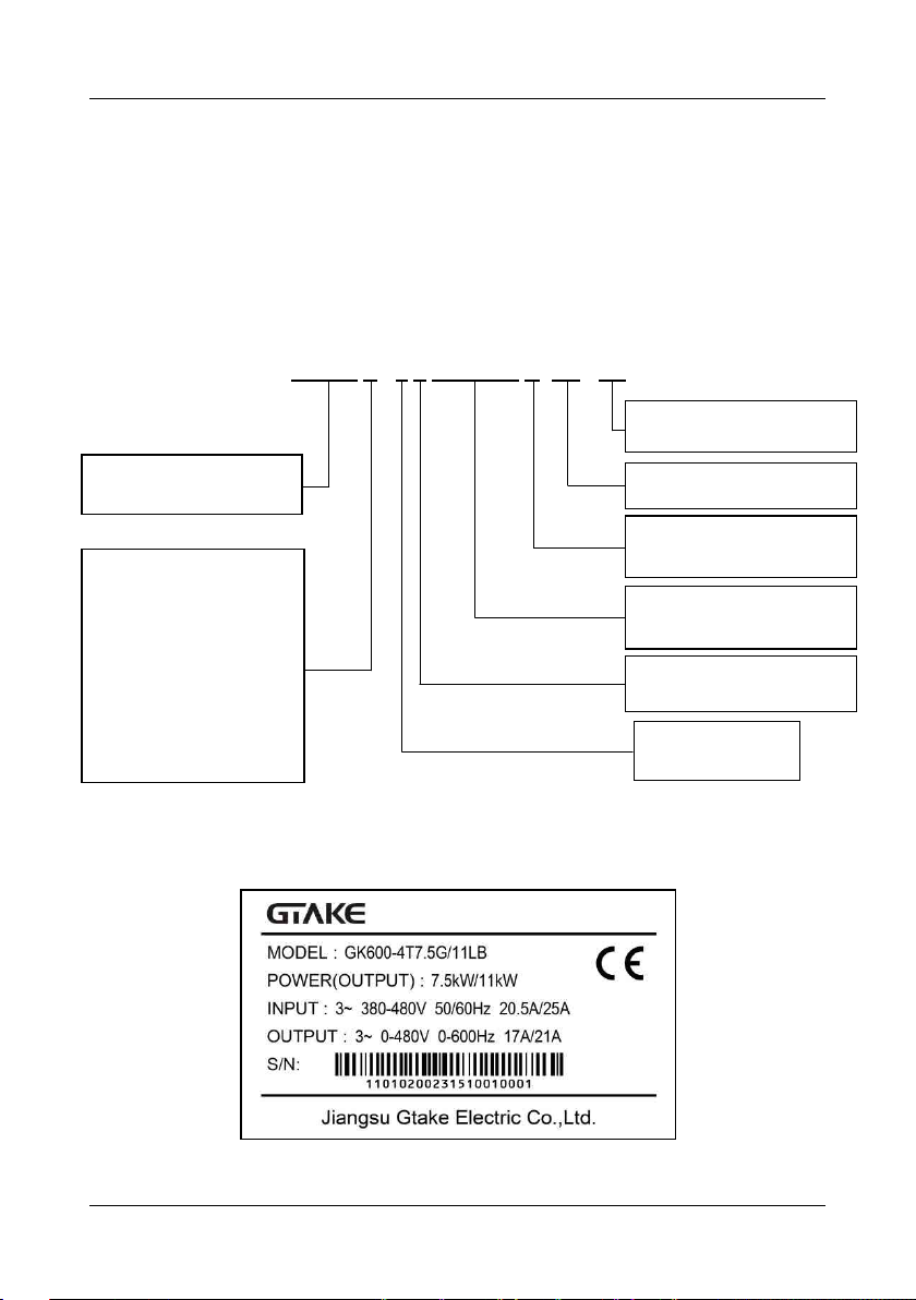
GK600 S - 4 T 7.5G/11L B- XX - XX
产品大系列代号
A0~Z9:code of customized
01~99:软件非标代号
7.5G:7.5kW(恒转矩/重载)
11L:11kW(变转矩/轻载)
S:单相
T:三相
缺省:无内置制动单元
B:内置制动单元
行业专用系列代号
缺省:通用系列
B:供水专用系列
S:拉丝机专用系列
M:机床专用系列
W:纺织专用系列
2:200V level
4:400V level
6:690V level
Master series code of product
Industry-specific series code
Default: general-purpose series
S: for drawing machine
I: for injection molding machine
…
A0-Z9: customized hardware code
01-99: customized software code
Default: without inbuilt brake chopper
B: with inbuilt brake chopper
7.5G: 7.5kW (constant torque/heavy
duty)
11L: 11kW (variable torque/light duty)
S: Single-phase
T: three-phase
Chapter 2 Product Information
2.1 Model Explanation
Model shown on product nameplate indicates the series name, applicable type of power supply,
power class and the version of software and hardware, etc. via the combination of numbers,
symbols and letters.
Fig. 2-1 Product model explanation
2.2 Nameplate Information
Fig. 2-2 Nameplate information
- 7 -
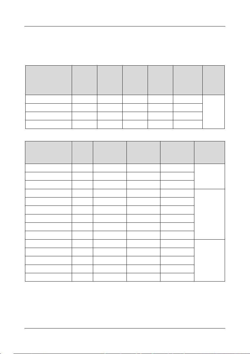
Chapter 2 Product Information GK600 User Manual
Drive model
Power
rating (kW)
3-phase
rated
output
current (A)
1-phase
rated input
current (A)
3-phase
rated input
current (A)
Applicable
motor (kW)
Brake
chopper
GK600-2T0.4B
0.4
2.6
5.5
3.2
0.4
Inbuilt
GK600-2T0.75B
0.75
4.5
9.2
6.3
0.75
GK600-2T1.5B
1.5
7.5
14.5
9
1.5
GK600-2T2.2B
2.2
11
23
15
2.2
Drive model
Power
rating
(kW)
3-phase rated
output current
(A)
3-phase rated
input current
(A)
Applicable
motor (kW)
Brake
chopper
GK600-2T3.7B
3.7
16.5
20.5
3.7
Inbuilt
GK600-2T5.5B
5.5
24
29
5.5
GK600-2T7.5B
7.5
30
35
7.5
GK600-2T11(B)
11
45
50
11
Inbuilt
optional
GK600-2T15(B)
15
60
65
15
GK600-2T18.5(B)
18.5
73
80
18.5
GK600-2T22(B)
22
91
95
22
GK600-2T30(B)
30
112
118
30
GK600-2T37(B)
37
144
150
37
GK600-2T45
45
176
160
45
Externally
mounted
when
needed
GK600-2T55
55
210
192
55
GK600-2T75
75
288
266
75
GK600-2T90
90
350
326
90
GK600-2T110
110
430
403
110
2.3 Information of Product Model
Table 2-1 Product model and technical data
■ GK600-2T□□□B, single/ three-phase 220V input, heavy duty
■ GK600-2T□□□□, three-phase 220V input, heavy duty
- 8 -
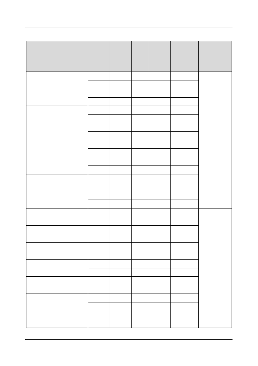
GK600 User Manual Chapter 2 Product Information
Drive model
Power
rating
(kW)
Rated
output
current
(A)
Rated
input
current
(A)
Applicable
motor (kW)
Brake
chopper
GK600-4T0.75G/1.5LB
0.75G
0.75
2.5
3.5
0.75
Inbuilt
1.5L
1.5
3.8
5.0
1.5
GK600-4T1.5G/2.2LB
1.5G
1.5
3.8
5.0
1.5
2.2L
2.2
4.8
5.5
2.2
GK600-4T2.2G/3.7LB
2.2G
2.2
5.5
6.0
2.2
3.7L
3.7
8.0
10
3.7
GK600-4T3.7G/5.5LB
3.7G
3.7
9.0
10.5
3.7
5.5L
5.5
11
14
5.5
GK600-4T5.5G/7.5LB
5.5G
5.5
13
14.6
5.5
7.5L
7.5
16
20
7.5
GK600-4T7.5G/11LB
7.5G
7.5
17
20.5
7.5
11L
11
21
25
11
GK600-4T11G/15LB
11G
11
24
29
11
15L
15
30
35
15
GK600-4T15G/18.5LB
15G
15
30
35
15
18.5L
18.5
36
40
18.5
GK600-4T18.5G/22L(B)*
18.5G
18.5
39
44
18.5
Inbuilt
optional
22L
22
45
50
22
GK600-4T22G/30L(B)*
22G
22
45
50
22
30L
30
56
60
30
GK600-4T30G/37L(B)*
30G
30
60
65
30
37L
37
72
76
37
GK600-4T37G/45L(B)*
37G
37
75
80
37
45L
45
91
95
45
GK600-4T45G/55L(B)*
45G
45
91
95
45
55L
55
112
118
55
GK600-4T55G/75L(B)*
55G
55
112
118
55
75L
75
142
148
75
GK600-4T75G/90L(B)*
75G
75
150
157
75
90L
90
176
180
90
■ GK600-4T□□□G/□□□L□, three-phase 400V input, heavy duty/ light duty
- 9 -
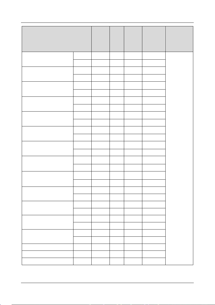
Chapter 2 Product Information GK600 User Manual
Drive model
Power
rating
(kW)
Rated
output
current
(A)
Rated
input
current
(A)
Applicable
motor (kW)
Brake
chopper
GK600-4T90G/110L
90G
90
176
160**
90
Externally
mounted
when needed
110L
110
210
192**
110
GK600-4T110G/132L
110G
110
210
192**
110
132L
132
250
230**
132
GK600-4T132G/160L
132G
132
253
232**
132
160L
160
304
280**
160
GK600-4T160G/185L
160G
160
310
285**
160
185L
185
350
326**
185
GK600-4T185G/200L
185G
185
350
326**
185
200L
200
380
354**
200
GK600-4T200G/220L
200G
200
380
354**
200
220L
220
430
403**
220
GK600-4T220G/250L
220G
220
430
403**
220
250L
250
470
441**
250
GK600-4T250G/280L
250G
250
470
441**
250
280L
280
520
489**
280
GK600-4T280G/315L
280G
280
520
489**
280
315L
315
590
571**
315
GK600-4T315G/355L
315G
315
590
571**
315
355L
355
650
624**
355
GK600-4T355G/400L
355G
355
650
624**
355
400L
400
725
699**
400
GK600-4T400G/450L
400G
400
725
699**
400
450L
450
820
790**
450
GK600-4T450G/500L
450G
450
820
790**
450
500L
500
860
835**
500
GK600-4T500G
500G
500
860
835**
500
GK600-4T560G
560G
560
950
920**
560
GK600-4T630G
630G
630
1100
1050**
630
* means brake chopper is optionally inbuilt. Take 18.5G/22L for example: the model without brake chopper is
- 10 -
GK600 User Manual Chapter 2 Product Information
Power input
Rated input
voltage
3-phase
AC208V/AC220V/AC230V/AC240V/AC380V/AC400V/
AC415V/AC440V/AC460V/AC480V
1-phase
AC220V/AC230V/AC240V
Frequency
50Hz/60Hz, tolerance ±5%
Voltage
range
Continuous voltage fluctuation ±10%, short fluctuation
-15%~+10%, i.e. 200V: 170V~264V, 400V: 323V~528V
Voltage out-of-balance rate <3%, distortion rate as per the
requirements of IEC61800-2
Rated input
current
See Section 2.3
Power output
Applicable
motor (kW)
See Section 2.3
Rated
current (A)
See Section 2.3
Output
voltage (V)
3-phase: 0~ rated input voltage, error < ±3%
Output
frequency
(Hz)
0.00~ 600.00Hz; unit: 0.01Hz
Overload
capacity
150% - 1min, 180% - 10s, 200% - 0.5s every 10 min
Control
characteristics
V/f patterns
V/f control
Sensor-less vector control 1
Sensor-less vector control 2
Range of
speed
regulation
1:100 ( V/f control, sensor-less vector control 1)
1:200 (sensor-less vector control 2)
GK600-4T18.5G/22L, and the model with brake chopper is GK600-4T18.5G/22LB. Braking resistor needs to be
mounted externally with reference to 3.4.3.
** means the rated input current configured a DC reactor. The drive GK600-4T90G/110L - GK600-4T500G is
provided with an external-mounted DC reactor in shipment as default. Be sure to connect the DC reactor. Failure to
comply may result in drive abnormal run. GK600-4T560G and GK600-4T630G are cabinet type, whose DC reactor
and output AC reactor are inbuilt as default.
2.4 Technical Features of GK600
Table 2-2 Technical Features of GK600
- 11 -
Chapter 2 Product Information GK600 User Manual
Control
characteristics
Speed
accuracy
±0.5% (V/f control)
±0.2% (sensor-less vector control 1 & 2)
Speed
fluctuation
±0.3% (sensor-less vector control 1 & 2)
Torque
response
< 10ms (sensor-less vector control 1 & 2)
Starting
torque
0.5Hz: 180% (V/f control, sensor-less vector control 1)
0.25Hz: 180% (sensor-less vector control 2)
Basic
functions
Start
frequency
0.00~ 600.00Hz
Accel/
Decel time
0.00~60000s
Switching
frequency
0.7kHz~16kHz
Frequency
setting
Digital setting + control panel ∧/∨
Digital setting + terminal UP/DOWN
Communication
Analog setting (AI1/AI2/EAI)
Terminal pulse setting
Motor
start-up
methods
Started from starting frequency
DC brake start-up
Flying start
Motor stop
methods
Ramp to stop
Coast to stop
Ramp stop + DC brake
Basic
functions
Dynamic
braking
capacity
Brake chopper working voltage:
200V level: 325-375V / 400V level: 650V-750V
Service time: 0-100.0s; brake chopper for
GK600-4T75G/90L and below are inbuilt or can be inbuilt
optionally. See table 2-1
DC brake
capacity
DC brake start frequency: 0.00~600.00Hz
DC brake current: 0.0~100.0%
DC brake time: 0.0~30.00s
Input
terminals
6 digital inputs, one of which can be used for high-speed
pulse input, and compatible with active open collectors
NPN, PNP and dry contact input. Digital inputs can be
extended to 7
2 analog inputs, one of which is voltage/current
programmable, and the other supports voltage only.
Analog inputs can be extended to 3, and the extended one
is voltage/current programmable
- 12 -
GK600 User Manual Chapter 2 Product Information
Basic
functions
Output
terminals
1 high-speed pulse output, 0~50kHz square wave signal
output. It can output signals such as frequency setting, or
output frequency, etc.
1 digital output
1 relay output (can be extended to 2)
1 analog output (can be extended to 2), voltage/current
output programmable; can output signals such as
frequency setting, or output frequency, etc.
Featured
functions
Parameter copy, parameter backup, common DC bus, free switchover
between two motors‟ parameters, flexible parameter displayed & hidden,
various master & auxiliary setting and switchover, flying start, a variety of
Accel/Decel curves optional, automatic correction of analog, brake
control, 16-step speed control programmable (2-step speed supports
flexible frequency command), wobble frequency control, fixed length
control, count function, three history faults, over excitation brake, over
voltage stall protection, under voltage stall protection, restart on power
loss, skip frequency, frequency binding, four kinds of Accel/Decel time,
motor thermal protection, flexible fan control, process PID control, simple
PLC, multi-functional key programmable, droop control, autotuning,
field-weakening control, high-precision torque restraint, V/f separated
control
Protection
functions
Refer to Chapter 7- Troubleshooting
Environment
Place of
operation
Indoors, no direct sunlight, free from dust, corrosive
gases, flammable gases, oil mist, water vapor, water drop
or salt, etc.
Altitude
0-2000m. De-rate 1% for every 100m when the altitude is
above 1000 meters
Ambient
temperature
-10℃-40℃. The rated output current should be derated
1% for every 1℃ when the ambient is 40℃-50℃
Relative
humidity
0~95%, no condensation
Vibration
Less than 5.9m/s2 (0.6g)
Storage
temperature
-40℃~+70℃
Others
Efficiency at
rated Amps
Rated power
7.5kW and below: ≥93%
11~ 45kW: ≥ 95%
55kW and above: ≥98%
Installation
560kW and 630kW are cabinet type,
the others are wall-mounted
IP grade
IP20
Cooling
method
Forced air cooling
- 13 -
铭牌
下壳体
安装孔
底板
风扇罩
防尘盖板
操作面板
盖板
中壳体
盖板
操作面板
安装孔
机箱
铭牌
风扇
托板
铭牌
机箱
安装孔
风扇
下盖板
操作面板
托板
上盖板
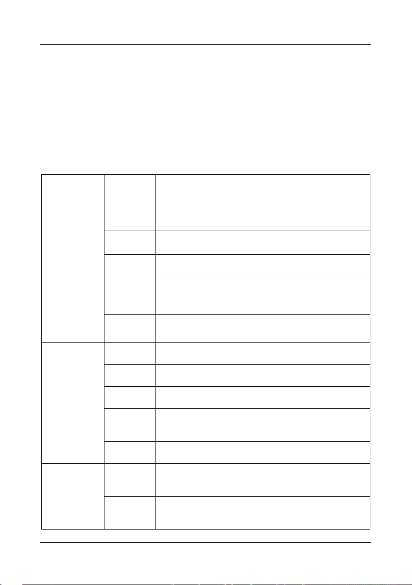
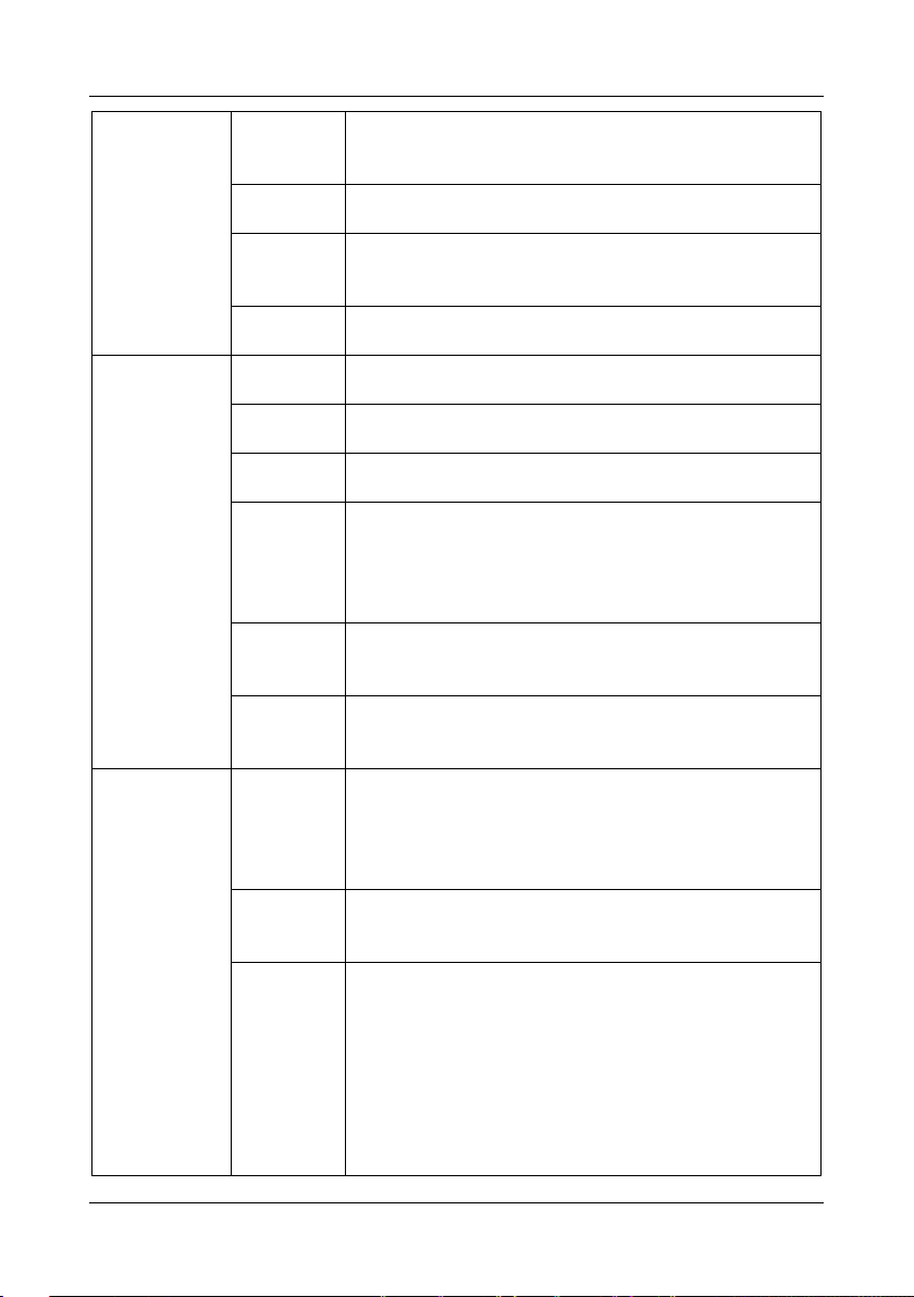
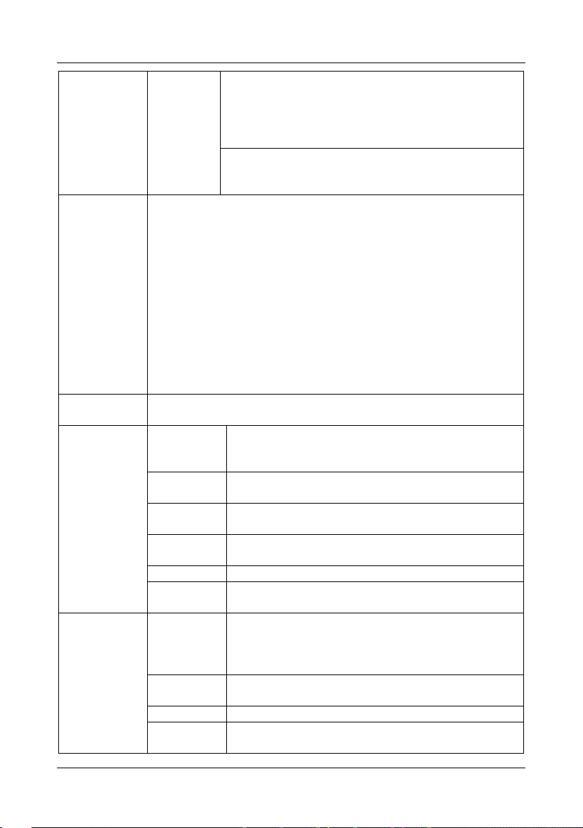
Fan cover
Dust cover
Control
panel
Cover
Control
panel
Cover
Base plate
Mounting
holes
Mounting
holes
Mounting
holes
Control
panel
Lower
casing
Nameplate
Nameplate
Nameplate
Middle casing
Control
panel
Fans
Enclosure
Fans
Enclosure
Control
panel
bracket
Upper
cover
Lower
cover
Nameplate
Chapter 2 Product Information GK600 User Manual
2.5 Parts Drawing
a) GK600-2T7.5B and below b) GK600-2T11(B) ~ GK600-2T37
GK600-4T15G/18.5LB and below GK600-4T18.5G/22L ~ GK600-4T75G/90L(B)
c) GK600-2T45 ~ GK600-2T110, GK600-4T90G/110L~ GK600-4T500G
- 14 -
GK600 User Manual Chapter 2 Product Information
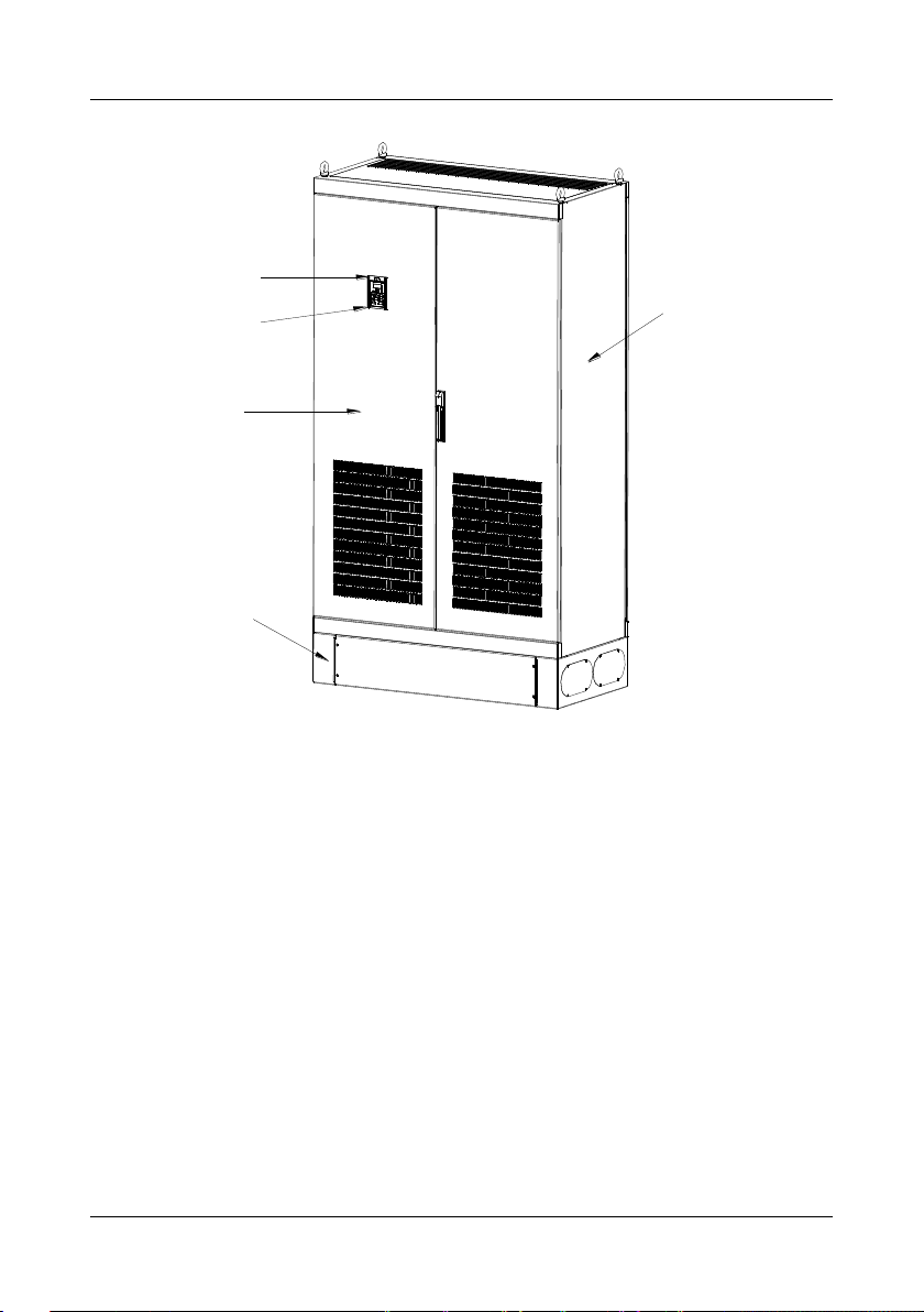
机柜
操作面板
托板
前门
底座
Control
panel
Control panel
bracket
Cabinet
Front
door
Cabinet
base
d) GK600-4T560G and GK600-4T630G
Fig. 2-3 Parts drawing
- 15 -
Chapter 2 Product Information GK600 User Manual
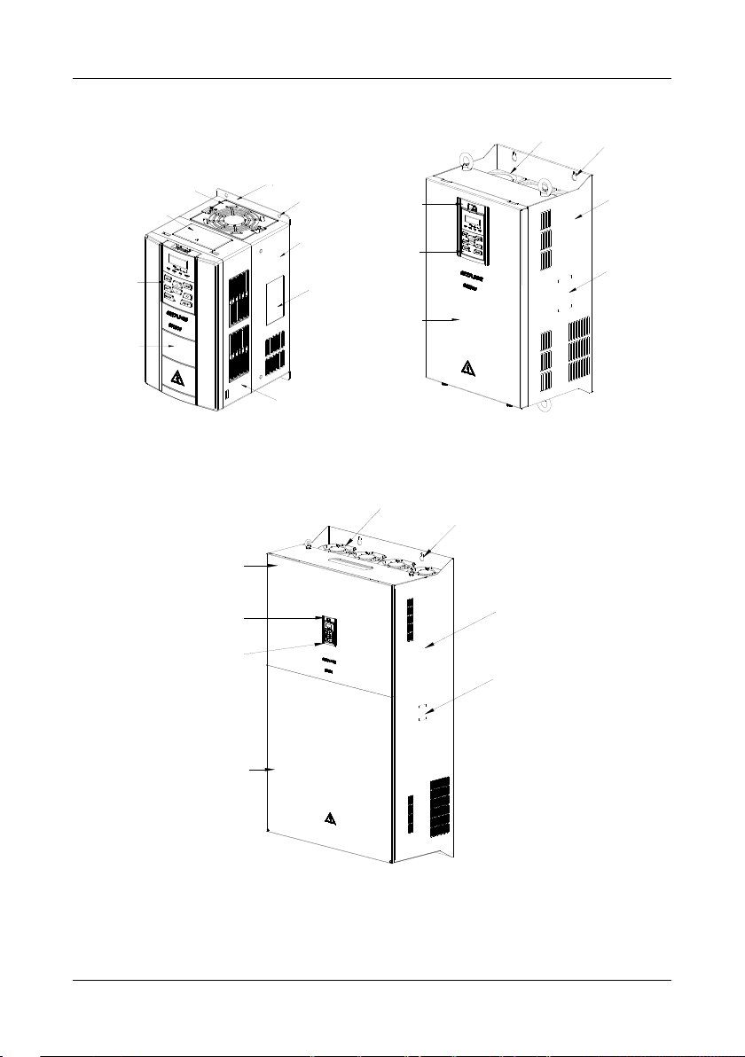
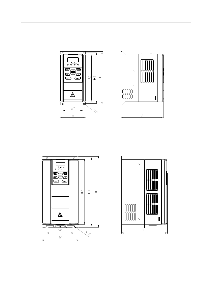
2.6 Appearance, Mounting Dimensions and Weight
a) GK600-2T0.4B ~ GK600-2T1.5B and
GK600-4T0.75G/1.5LB ~ GK600-4T1.5G/2.2LB
b) GK600-2T2.2B ~ GK600-2T7.5B, GK600-4T2.2G/3.7LB ~ GK600-4T15G/18.5LB
- 16 -
GK600 User Manual Chapter 2 Product Information
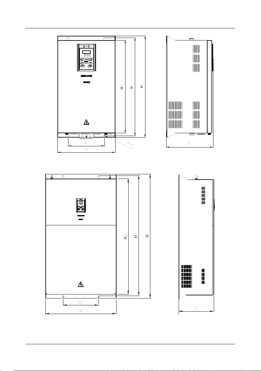
c) GK600-2T11(B) ~ GK600-2T37, GK600-4T18.5G/22L(B) ~ GK600-4T75G/90L(B)
d) GK600-2T45 ~ GK600-2T75, GK600-4T90G/110L ~ GK600-4T160G/185L
- 17 -
Chapter 2 Product Information GK600 User Manual
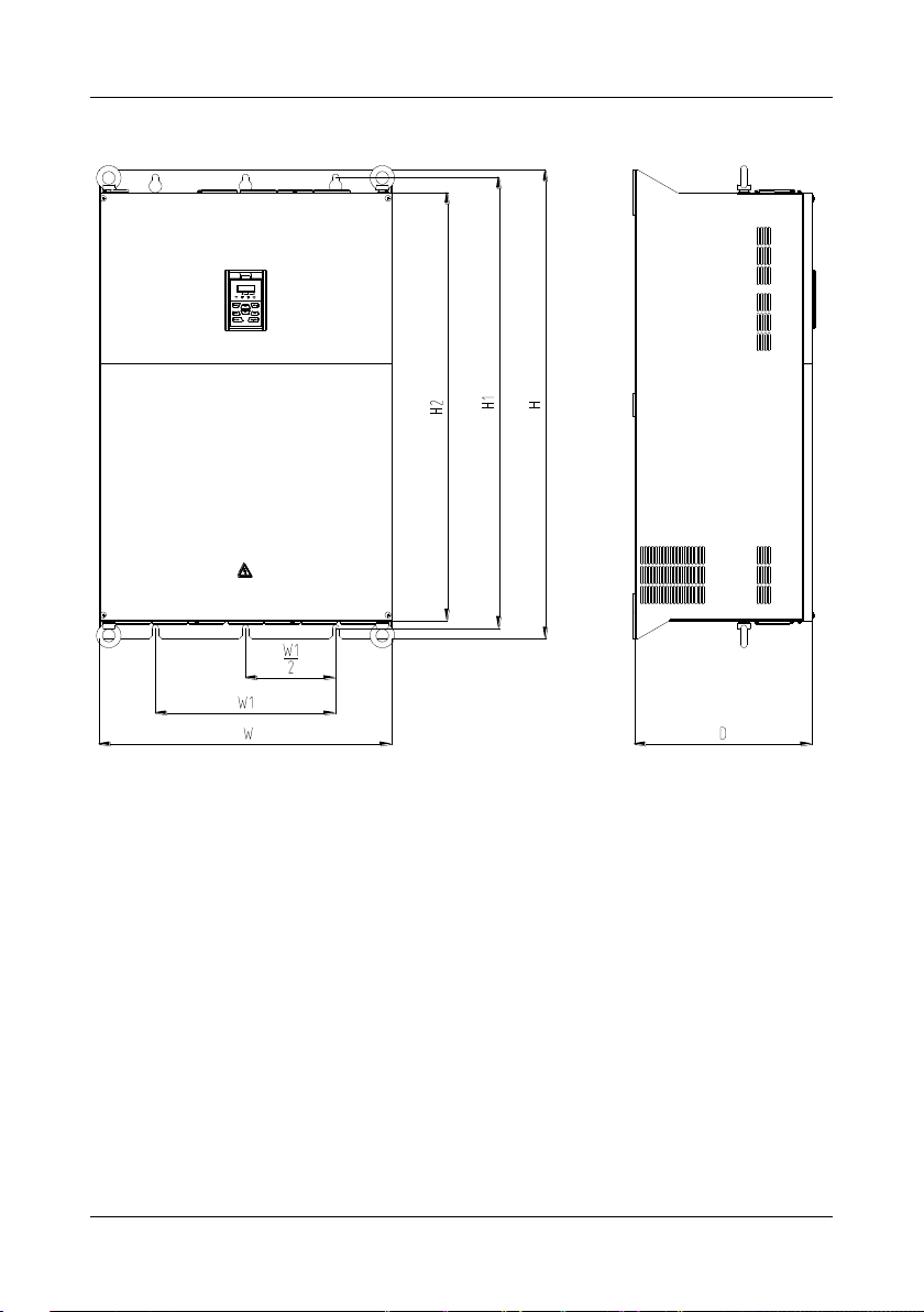
e) GK600-2T90 ~ GK600-2T110, GK600-4T185G/200L ~ GK600-4T500G
- 18 -
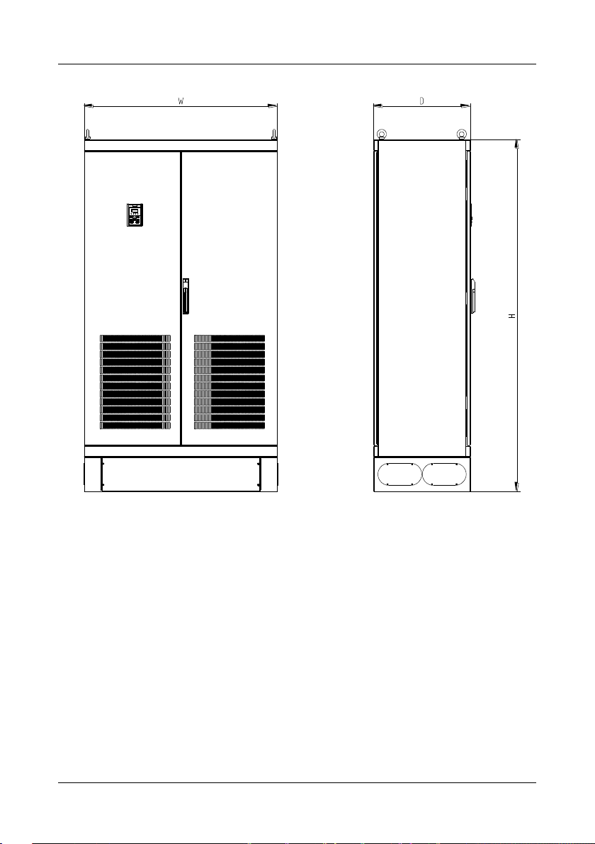
GK600 User Manual Chapter 2 Product Information
f) GK600-4T560G ~ GK600-4T630G
Fig. 2-4 External dimensions
- 19 -
Chapter 2 Product Information GK600 User Manual
Model
External and installation dimensions (mm)
Weight
(kg)
W H D
W1
H1
H2
Mounting
hole dia.
GK600-2T0.4B
93
190
152
70
180
172
4.5
1.4
GK600-2T0.75B
GK600-2T1.5B
GK600-2T2.2B
120
245
169
80
233
220
5.5
2.9
GK600-2T3.7B
145
280
179
105
268
255
5.5
3.9
GK600-2T5.5B
190
365
187
120
353
335 6 6.2
GK600-2T7.5B
GK600-2T11(B)
270
475
220
170
460
435 8 15.5
GK600-2T15(B)
GK600-2T18.5(B)
320
568
239
220
544
515
10
24
GK600-2T22(B)
GK600-2T30
385
670
261
260
640
600
12
37
GK600-2T37
GK600-2T45
395
785
291
260
750
705
12
50
GK600-2T55
GK600-2T75
440
900
356
300
865
820
14
66
GK600-2T90
500
990
368
360
950
900
14
88
GK600-2T110
650
1040
406
400
1000
950
14
123
GK600-4T0.75G/1.5LB
93
190
152
70
180
172
4.5
1.4
GK600-4T1.5G/2.2LB
GK600-4T2.2G/3.7LB
120
245
169
80
233
220
5.5
2.9
GK600-4T3.7G/5.5LB
GK600-4T5.5G/7.5LB
145
280
179
105
268
255
5.5
3.9
GK600-4T7.5G/11LB
Table 2-3 Appearance, mounting dimensions and weight
- 20 -

GK600 User Manual Chapter 2 Product Information
GK600-4T11G/15LB
190
365
187
120
353
335 6 6.2
GK600-4T15G/18.5LB
GK600-4T18.5G/22L(B)
270
475
220
170
460
435 8 15.5
GK600-4T22G/30L(B)
GK600-4T30G/37L(B)
GK600-4T37G/45L(B)
320
568
239
220
544
515
10
24
GK600-4T45G/55L(B)
GK600-4T55G/75L
385
670
261
260
640
600
12
37
GK600-4T75G/90L
GK600-4T90G/110L
395
785
291
260
750
705
12
50
GK600-4T110G/132L
GK600-4T132G/160L
440
900
356
300
865
820
14
66
GK600-4T160G/185L
GK600-4T185G/200L
500
990
368
360
950
900
14
88
GK600-4T200G/220L
GK600-4T220G/250L
650
1040
406
400
1000
950
14
123
GK600-4T250G/280L
GK600-4T280G/315L
GK600-4T315G/355L
815
1300
428
600
1252
1200
14
165
GK600-4T355G/400L
GK600-4T400G/450L
815
1300
428
600
1252
1200
14
165
GK600-4T450G/500L
GK600-4T500G
GK600-4T560G
1100
2000
550 / / / /
515
GK600-4T630G
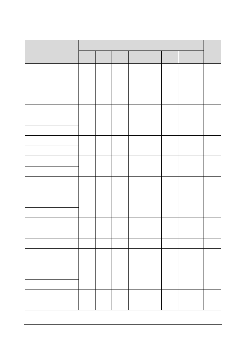
2.7 External Dimensions of Control Panel
Control panel model of GK600 series general purpose AC motor drive is KBU-BX1 whose
appearance and external dimensions are shown in Fig. 2-5.
- 21 -
Chapter 2 Product Information GK600 User Manual
Panel TH Hole WTH
1.2mm 73.2mm
1.5mm 74.4mm
2mm 75.5mm
Fig. 2-5 External dimensions of KBU-BX1
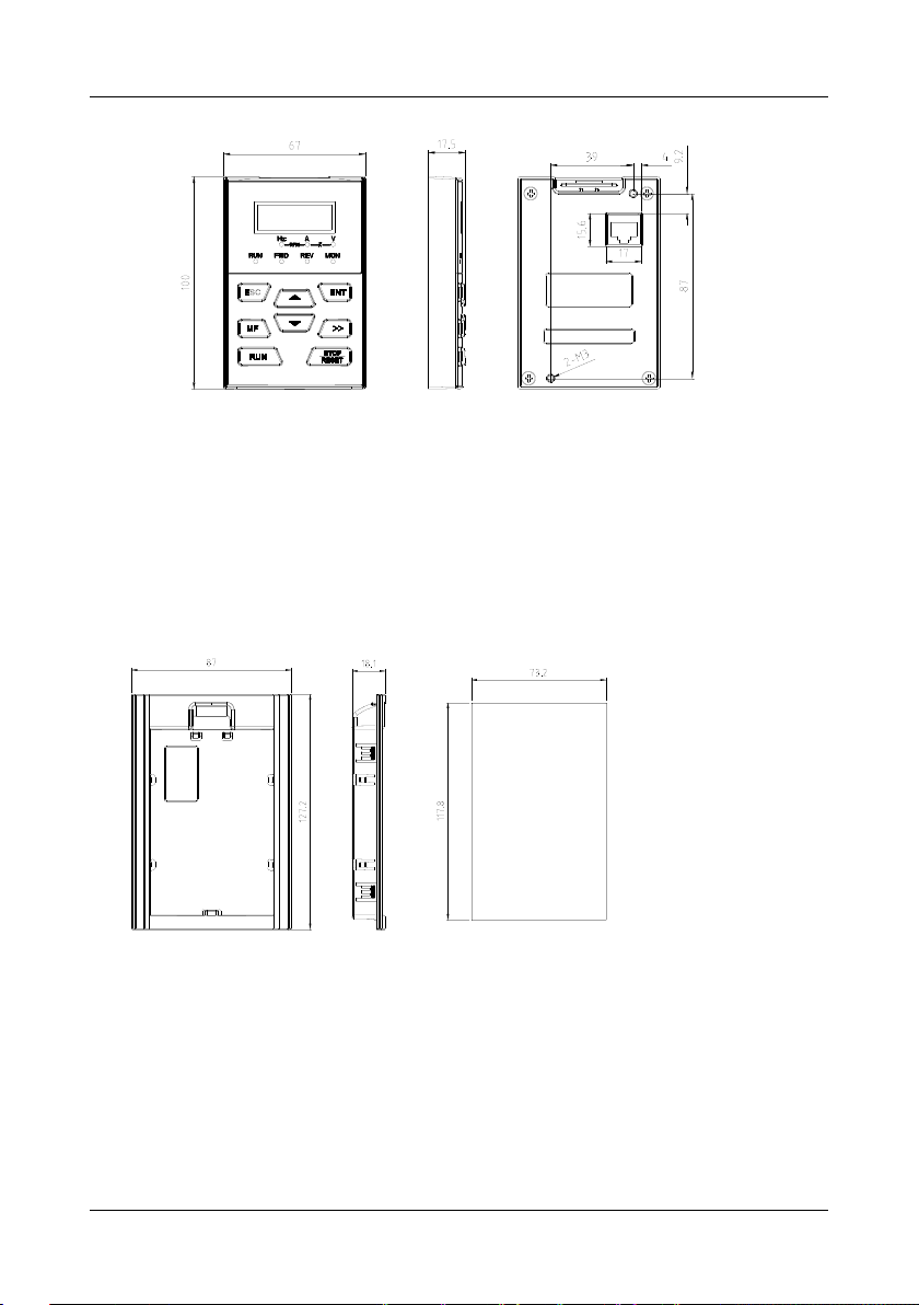
2.8 External Dimensions of Control Panel Bracket
A bracket should be provided to support the panel and a hole in the cabinet needs to be opened
when the control panel KBU-BX1 needs to be remotely used. Bracket model is KBU-DZ1
whose external dimensions are shown in Fig. 2-6 a). Fig. 2-6 b) shows applicable hole
dimensions in the cabinet.
a) External dimensions of KBU-DZ1 b) Hole dimensions in the cabinet
Fig. 2-6 External dimensions of KBU-DZ1 and cabinet hole dimensions
- 22 -
 Loading...