

GTAKE GK500-2T0.4B, GK500-2T0.75B, GK500 Series, GK500-4T0.75B, GK500-4T1.5B User Manual
...

IMPORTANT NOTES
Please assure the intactness of product enclosure and all safety covers before
installation. Operation must conform to the requirements of this manual and local
industrial safety regulations and/or electrical codes.
Contents of this manual may be subject to appropriate modification as a result of
product upgrade, specification change and update of the manual.
In the event of damage or loss of user manual, users may ask local distributors,
offices or our Technical Service Department for a new one.
If any item as stated in this manual is not clear, please contact our Technical
Service Department.
If any anomaly occurs after power up or during the operation, it is essential to
stop the machine and identify the fault or seek technical services as soon as
possible.
Telephone number of our International Technical Service Department: +86-
0755-86392601.
Preface
Thank you for choosing GTAKE GK500 Series Mini AC Motor Drives. This user manual
presents a detailed description of GK500 series with respect to product features,
structural characteristics, functions, installation, parameter setting, troubleshooting,
commissioning and daily maintenance, etc. Be sure to carefully read through the safety
precautions before use, and use this product on the premise that personnel and
equipment safety is ensured.
Chapter 2
1
Table 2-3 updated
Chapter 3
1
Fig. 3-5, Fig. 3-7, Fig. 3-8, Fig. 3-13 updated
2
Fig. 3-9, Fig. 3-10 added
Summary of Changes
The information below summaries changes made in May 2016 for GK500 Series Mini AC
Motor Drives User Manual, version A01-EN.
Besides there are some changes on the manner of writing, error correction, and
designation replacement like control panel instead of keypad, following is the material
new or updated information in this user manual.

Table of Contents
Preface ........................................................................................................ - 1 -
Table of Contents ....................................................................................... - 3 -
Chapter 1 Safety Precautions ................................................................... - 1 -
1.1 Safety Considerations ................................................................. - 1 -
1.2 Other Considerations .................................................................. - 5 -
Chapter 2 Product Information ................................................................. - 7 -
2.1 Model Explanation ....................................................................... - 7 -
2.2 Nameplate Information ................................................................ - 7 -
2.3 Information of Product Model ...................................................... - 8 -
2.4 Technical Features of GK500 ...................................................... - 8 -
2.5 Parts Drawing ............................................................................ - 11 -
2.6 Configuration, Mounting Dimensions and Weight ..................... - 11 -
2.7 External Dimensions of Control Panel ....................................... - 12 -
Chapter 3 Installation and Wiring ........................................................... - 14 -
3.1 Installation Environment ............................................................ - 14 -
3.2 Minimum Mounting Clearances ................................................. - 14 -
3.3 Remove & Mount the Control Panel and Cover ........................ - 15 -
3.4 Selection of Peripheral Devices ................................................ - 16 -
3.5 Terminal Configuration .............................................................. - 17 -
3.6 Main Circuit Terminals and Wiring ............................................. - 17 -

3.7 Control Terminal Wiring ............................................................. - 19 -
3.8 Control Terminal Specification ................................................... - 21 -
3.9 Control Terminal Usage ............................................................. - 22 -
3.10 Instruction of Signal Switches ................................................... - 26 -
3.11 EMI Solutions ............................................................................ - 26 -
Chapter 4 Operation and Run Instructions ............................................ - 30 -
4.1 Operation of Control Panel ........................................................ - 30 -
4.2 Key Functions ........................................................................... - 30 -
4.3 Control panel Indicators ............................................................ - 31 -
4.4 Potentiometer Setting ................................................................ - 32 -
4.5 Prompt Message Status ............................................................ - 32 -
4.6 Parameter Setting ..................................................................... - 33 -
Chapter 5 List of Parameters .................................................................. - 34 -
Chapter 6 Troubleshooting ..................................................................... - 65 -
6.1 Fault Causes and Troubleshooting............................................ - 66 -
Chapter 7 Maintenance............................................................................ - 73 -
7.1 Routine Inspection .................................................................... - 73 -
7.2 Regular Maintenance ................................................................ - 74 -
7.3 Replacement of Vulnerable Parts .............................................. - 75 -
7.4 Storage ...................................................................................... - 76 -
GK500 User Manual Chapter 1 Safety Precautions
WARNING
Do not use the drive whose component(s) is/are missing or damaged. Failure to
comply with may result in more faults and/or personal injury even death.
ATTENTION
Check if the product information indicated on the nameplate is consistent with the
order requirements. If not, do not install it.
Do not install the drive in the event that the packing list does not match with real
equipment.
WARNING
Only qualified personnel familiar with adjustable frequency AC drives and associated
machinery should plan or implement the installation. Failure to comply may result in
equipment damage and/or personnel injury even death.
Chapter 1 Safety Precautions
Safety Precautions
Safety signs in this manual:
WARNING: indicates the situation in which the failure to follow operating
requirements may result in fire or serious personal injury or even death.
ATTENTION: indicates the situation in which the failure to follow operating
requirements may cause moderate or slight injury and damage to equipment.
Users are requested to read this chapter carefully when installing, commissioning and
repairing this product and perform the operation according to safety precautions as set
forth in this chapter without breach. GTAKE will bear no responsibility for any injury and
loss as a result of any inappropriate operation.
1.1 Safety Considerations
1.1.1 Prior to Installation
1.1.2 Installation
- 1 -
Chapter 1 Safety Precautions GK500 User Manual
This equipment must be mounted on metal or other flame retardant objects. Failure to
comply may result in fire.
This equipment must be mounted in an area which is away from combustibles and
heat sources. Failure to comply may result in fire.
This equipment must in no case be mounted in the environment exposed to explosive
gases. Failure to comply may result in explosion.
Never adjust mounting bolts of this equipment, especially the ones with red markers.
Failure to comply may result in equipment damage.
ATTENTION
Handle the equipment gently and take hold of its sole plate so as to avoid foot
injury or equipment damage.
Mount the equipment where its weight can be withstood. Failure to comply may
result in equipment damage and/or personnel injury if falling happens.
Make sure the installation environment conform to the requirements as stated in
Section 2.4. If not, de-rating is necessary. Failure to comply may result in equipment
damage.
Prevent drilling residues, wire ends and screws from falling into the equipment
during installation. Failure to comply may result in faults or equipment damage.
When mounted in a cabinet, this equipment should be provided with appropriate
heat dissipation. Failure to comply may result in faults or equipment damage.
WARNING
Only qualified personnel familiar with adjustable frequency AC drives and associated
machinery should plan or implement the wiring. Failure to comply may result in
personnel injury and/or equipment damage.
Wiring must strictly conform to this manual. Failure to comply may result in
personnel injury and/or equipment damage.
Make sure the input power supply has been completely disconnected before
wiring. Failure to comply may result in personnel injury and/or equipment damage.
All wiring operations must comply with EMC and safety regulations and/or
electrical codes, and the conductor diameter should conform to recommendations
of this manual. Failure to comply may result in personnel injury and/or equipment
damage.
Since overall leakage current of this equipment may be bigger than 3.5mA, for
1.1.3 Wiring
- 2 -
GK500 User Manual Chapter 1 Safety Precautions
safety's sake, this equipment and its associated motor must be well grounded so
as to avoid the risk of electric shock.
Be sure to implement wiring in strict accordance with the marks on this
equipment’s terminals. Never connect three-phase power supply to output
terminals U/T1, V/T2 and W/T3. Failure to comply will result in equipment damage.
Install braking resistors at terminals /B1 and B2 only. Failure to comply may
result in equipment damage.
Wiring screws and bolts for main circuit terminals must be screwed tightly. Failure
to comply may result in equipment damage.
AC 220V signal is prohibited from connecting to other terminals than control
terminals RA, RB and RC. Failure to comply will result in equipment damage.
ATTENTION
Since all adjustable frequency AC drives from GTAKE have been subjected to
hi-pot test before delivery, users are prohibited from implementing such a test on
this equipment. Failure to comply may result in equipment damage.
Signal wires should to the best of the possibility be away from main power lines. If
this cannot be ensured, vertical cross-arrangement shall be implemented,
otherwise interference noise to control signal may occur.
If motor cables are longer than 100m, it is recommended output AC reactor be
used. Failure to comply may result in faults.
WARNING
Drives which have been stored for more than 2 years should be used with voltage
regulator to gradually boost the voltage when applying power to the drives. Failure
to comply may result in equipment damage.
Be sure to confirm the completion and correctness of the drive wiring and close
the cover before applying power to the drive. Do not open the cover after applying
power. Failure to comply may result in electric shock hazard.
After applying the power, never touch the drive and peripheral circuits no matter
what state the drive is under, otherwise there will be electric shock hazard.
Prior to the run of the drive, check there is no person in surrounding area who can
reach the motor and its load so as to prevent personal injury.
Only qualified technicians familiar with adjustable frequency AC drives are
allowed to perform signal test during operation. Failure to comply may result in
1.1.4 Run
- 3 -
Chapter 1 Safety Precautions GK500 User Manual
equipment damage and/or personal injury.
Never change the drive parameters at will. Failure to comply may result in
equipment damage.
ATTENTION
Make sure the number of phases of power supply and rated voltage are consistent
with product nameplate. If not, contact the seller or GTAKE.
Check there are no short circuits in peripheral circuits connected with the drive,
and make sure the connection is tight. Failure to comply may result in equipment
damage.
Make sure the motor and associated machinery are within allowable range of
service prior to operation. Failure to comply may result in equipment damage.
Never touch fans, heat sink and braking resistor with bare hands. Failure to
comply may result in equipment damage and/or personal injury.
It is not allowed to start & stop the driver frequently via direct switching power on
or off. Failure to comply may result in equipment damage.
Make sure the drive is in a non-output status before switch-on/switch-off of the
drive output and/or contactor. Failure to comply may result in equipment damage.
WARNING
Only qualified technicians are allowed to implement the maintenance, and
troubleshooting.
Never implement the maintenance, and troubleshooting before power supply has
been cut off and discharged completely. Failure to comply may result in
equipment damage and/or personal injury.
To avoid an electric shock hazard, wait at least 10 minutes after the power has
been cut off and make sure the residual voltage of the bus capacitors has
discharged to 0V before performing any work on the drive.
After the replacement of the drive, be sure to perform the same procedures in
strict accordance with above-noted rules.
ATTENTION
Do not touch the electric components with bare hands without electrostatic
protective measures during maintenance, and troubleshooting. Failure to do this
may result in component damage caused by ESD.
1.1.5 Maintenance
- 4 -

GK500 User Manual Chapter 1 Safety Precautions
All pluggable components can be inserted or pulled out only when power has
been cut off.
1.2 Other Considerations
1.2.1 Input Power Supply
This series of drives are not applicable to applications out the range of operating voltage
as set forth in this manual. If the input voltage is not in the required range, please use
booster to rise or drop the voltage to the stated voltage range.
1.2.2 Surge Protection
This series of drives are furnished with surge suppressor that has certain resistance to
lightning induction. However, users in areas with frequent occurrence of lightning need to
mount an external surge suppressor in front of the drive power input side.
1.2.3 Operation of Contactor
As to the configuration of peripheral devices recommended by this manual, it is
necessary to mount a contactor between the power supply and this drive input side.
Such a contactor should not be used as a control device for start and stop of the drive, as
frequent charging & discharging shall reduce the service life of internal electrolytic
capacitors.
When it is necessary to mount a contactor between the drive output and the motor, it
should be ensured the drive is in a non-output status before switch-on/switch-off of such
a contactor. Failure to comply may result in drive damage.
1.2.4 Output Filter
Since the drive output is PWM high frequency chopping voltage, mounting filter devices
such as an output filter and an output AC reactor between the motor and the drive shall
effectively reduce output noise, avoiding interference to other surrounding equipments.
If the length of cable between the drive and the motor exceeds 100m, an output AC
reactor is recommended to use with the purpose of preventing drive fault as a result of
overcurrent caused by excessive distributed capacitance. An output filter is optional
depending on field requirements.
Be sure not to mount phase-shifting capacitor or surge absorber at output side of the
- 5 -

Chapter 1 Safety Precautions GK500 User Manual
drive since this may result in drive damage as a result of over-temperature.
1.2.5 Insulation of the motor
In view of the fact that the drive output is PWM high frequency chopping voltage
accompanied by higher harmonics, the noise, temperature rise and vibration of the motor
is higher compared with sinusoidal voltage. Particularly this debases motor insulation.
Therefore, the motor should be subjected to insulation inspection before initial use or
reuse after being stored for a long period of time. The motor in regular service should
also be subjected to regular insulation inspection so as to avoid the drive damage as a
result of motor insulation damage.
1.2.6 Derating
The drive heat dissipation by forced air cooling degrades ascribed to the thin air in
high-altitude areas, as well as the electrolyte of electrolytic capacitors is more volatile,
which can result in reduction in product life. Drive should be derated when used in an
area at the altitude above 1000 meters. It is recommended to derate 1% for every 100m
when the altitude is above 1000 meters.
- 6 -
GK500 User Manual Chapter 2 Product Information
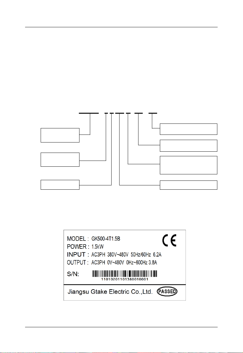
GK500 - 4 T 1.5 B- XX - XX
Product Series
A0~Z9:customized hardware code
01~99:customized software code
1.5:1.5kW
T:triphase
Default:no inbuilt brake chopper
B:with inbuilt brake chopper
2:200V
4:400V
Chapter 2 Product Information
2.1 Model Explanation
Model shown on product nameplate indicates the series name, applicable type of power
supply, power class and the version of software and hardware, etc. via the combination
of numbers, symbols and letters.
2.2 Nameplate Information
Fig. 2-1 Product model explanation
Fig. 2-2 Nameplate information
- 7 -
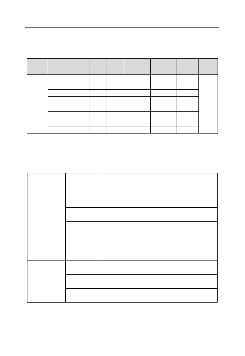
Chapter 2 Product Information GK500 User Manual
Voltage
Model
Power
rating
(kW)
Output
current
(A)
Triphase
input current
(A)
Single-phase
input current
(A)
Applicable
motor
(kW)
Brake
unit
200V*
GK500-2T0.4B
0.4
2.6
3.2
5.5
0.4
inbuilt
GK500-2T0.75B
0.75
4.5
6.3
9.2
0.75
GK500-2T1.5B
1.5
7.5 9 14.5
1.5
GK500-2T2.2B
2.2
9.6
15
23
2.2
400V
GK500-4T0.75B
0.75
2.5
3.5 / 0.75
GK500-4T1.5B
1.5
3.8
6.2 / 1.5
GK500-4T2.2B
2.2
5.5
9.2 / 2.2
GK500-4T3.7B
3.7 9 14.9 / 3.7
Power input
Rated input
voltage
3-phase
AC208V/AC220V/AC230V/AC240V/AC380V
/AC400V/AC415V/AC440V/AC460V/AC480V
1-phase
AC220V/AC230V/AC240V
Rated input
current
See Section 2.3
Frequency
50Hz/60Hz, tolerance ±5%
Voltage
range
Continuous voltage fluctuation ±10%, short
fluctuation -15%~+10%
Voltage out-of-balance rate <3%, distortion rate as
per the requirements IEC61800-2
Power output
Applicable
motor (kW)
See Section 2.3
Rated
current (A)
See Section 2.3
Output
voltage (V)
3-phase: 0~ rated input voltage, error < ±3%
2.3 Information of Product Model
Table 2-1 Product model and technical data
* 200V drives are applicable for triphase 200V and single-phase 200V.
2.4 Technical Features of GK500
Table 2-2 Technical Features of GK500
- 8 -

GK500 User Manual Chapter 2 Product Information
Power output
Output
frequency
(Hz)
0.00~ 600.00Hz; unit: 0.01Hz
Overload
capacity
150% - 1min; 180% - 10s; 200% - 0.5s
Control
characteristics
V/f patterns
V/f control
Sensor-less vector control 1
Speed
regulation
range
1:100 ( V/f , sensor-less vector control 1)
Speed
accuracy
±0.5% (V/f control)
±0.2% (sensor-less vector control 1)
Speed
fluctuation
±0.3% (sensor-less vector control 1)
Torque
response
< 10ms (sensor-less vector control 1)
Starting
torque
0.5Hz: 180% (V/f control, sensor-less vector control
1)
Basic
functions
Start
frequency
0.00~ 600.00Hz
Accel/
Decel time
0.00~60000s
Switching
frequency
0.7kHz~12kHz
Frequency
setting
Digital setting + control panel ∧/∨
Digital setting + terminal UP/DOWN
Potentiometer
Communication
Analog setting (AI1)
Motor
start-up
methods
Started from starting frequency
DC brake start-up
Motor stop
methods
Ramp to stop
Coast to stop
Ramp stop + DC brake
Dynamic
braking
capacity
Brake chopper working voltage:
400V input: 650V~750V
200V input: 325V~375V
service time: 0.0~100.0s
- 9 -

Chapter 2 Product Information GK500 User Manual
DC brake
capacity
DC brake start frequency: 0.00~600.00Hz
DC brake current: 0.0~100.0%
DC brake time: 0.0~30.00s
Basic
functions
Input
terminals
4 digital inputs
1 analog, current/voltage programmable
Output
terminals
1 digital output
1 relay output
1 analog output, voltage/current programmable; can
output signals such as frequency setting, or output
frequency, etc
Featured
functions
various master & auxiliary commands, a variety of Accel/Decel
curves programmable, analog auto correction, 8-step speed
programmable, three faults history, over excitation brake, over
voltage stall protection, under voltage stall protection, restart upon
power loss, skip frequency, frequency binding, four kinds of
Accel/Decel time, process PID, autotuning, field-weakening control
Protection
functions
Refer to Chapter 6- Troubleshooting
Environment
Place of
operation
Indoors, no direct sunlight, free from dust, no
corrosive gases, no flammable gases, no oil mist,
no water vapor, no water drop and salt, etc.
Altitude
0~2000m
De-rate 1% for every 100m when the altitude is
above 1000 meters
Ambient
temperature
-10℃~50℃
Relative
humidity
0~95%, no condensation
Vibration
Less than 5.9m/s2 (0.6g)
Storage
temperature
-40℃~+70℃
Others
Efficiency at
rated Amps
At rated Amps ≥93%
Installation
Wall-mounted, Din-rail
IP grade
IP20
Cooling
method
Forced air cooling
- 10 -
GK500 User Manual Chapter 2 Product Information
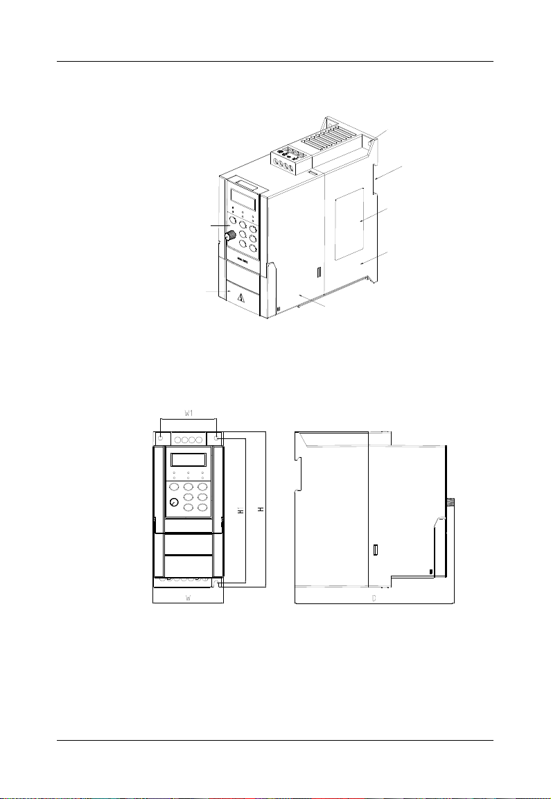
Control
panel
Cover
Mounting
holes
DIN-rail
groove
Nameplate
Lower
casing
Middle
casing
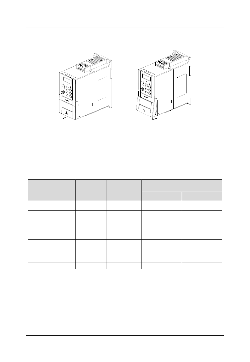
2.5 Parts Drawing
Fig. 2-3 Parts drawing
2.6 Configuration, Mounting Dimensions and Weight
Fig. 2-4 External dimensions
- 11 -

Chapter 2 Product Information GK500 User Manual
Model
Dimensions(mm)
Weight
W H D
W1
H1
Mounting
holes (dia)
(kg)
GK500-2T0.4B
75
166
168
59
154
4.5
1.25
GK500-2T0.75B
GK500-4T0.75B
GK500-4T1.5B
GK500-2T1.5B
85
188
172
69
175
4.5
1.7
GK500-2T2.2B
GK500-4T2.2B
GK500-4T3.7B
Table 2-3 Dimensions and weight
2.7 External Dimensions of Control Panel
Control panel model of GK500 series mini AC motor drive is KBU-BX2 whose
configuration and external dimensions are shown in Fig. 2-5. The cabinet hole
dimensions are as shown in Fig. 2-6. when remote control panel mounting is required.
Fig. 2-5 External dimensions of KBU-BX2
- 12 -
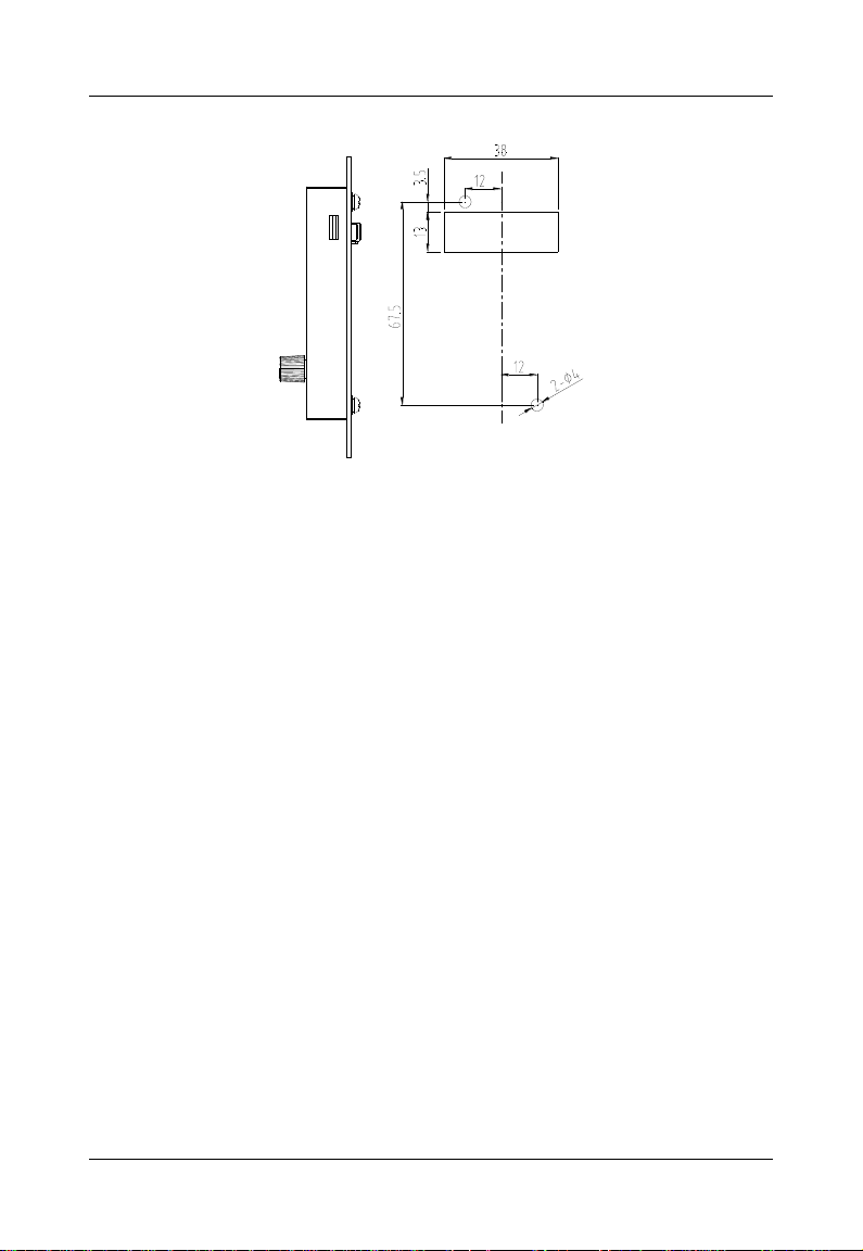
GK500 User Manual Chapter 2 Product Information
Fig. 2-6 Cabinet hole dimensions when control panel remote mounting required
- 13 -
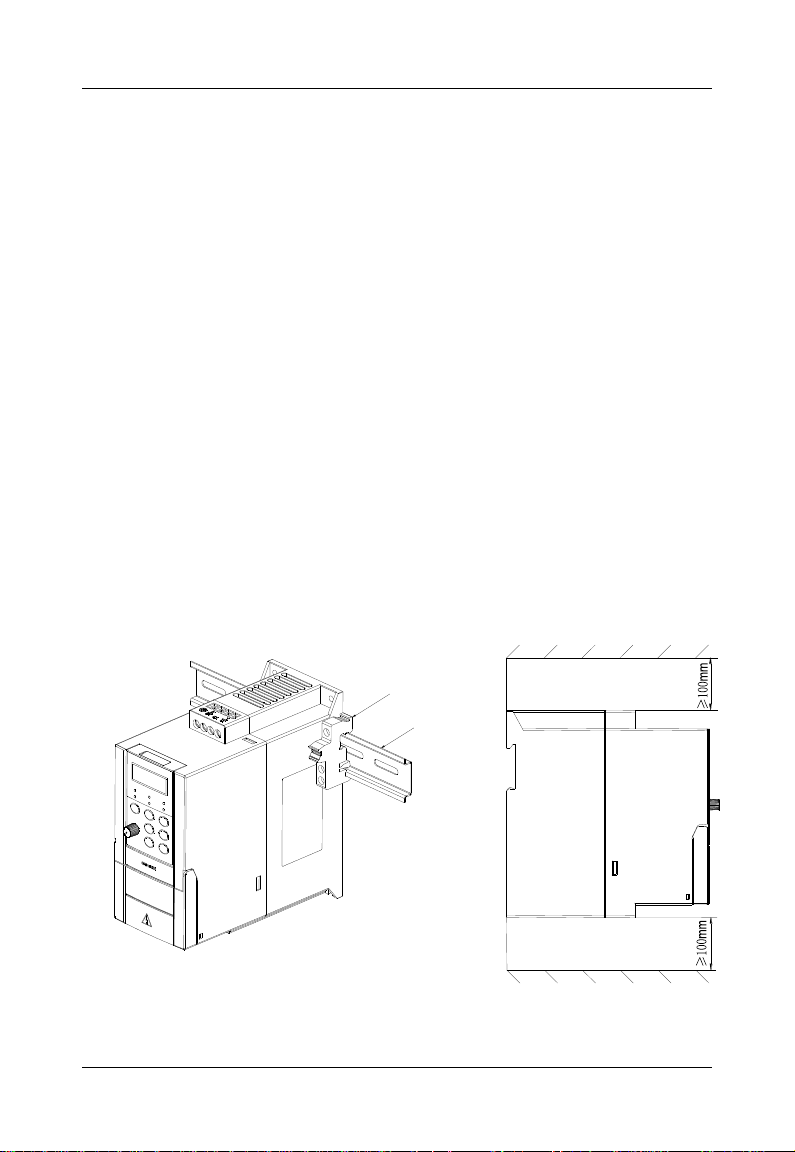
Chapter 3 Installation and Wiring GK500 User Manual
Fixing buckle
DIN-Rail
Ventilation
clearance
Ventilation
clearance
Chapter 3 Installation and Wiring
3.1 Installation Environment
1) Ambient temperature should be in the range of -10℃~ 50℃.
2) Drive should be installed on surface of flame retardant object, with adequate
surrounding space for heat dissipation.
3) Installation should be performed where vibration is less than 5.9m/s2 (0.6g).
4) No moisture and direct sunlight.
5) Do not install in areas with grease dirt, dust, metal particles, or salty substances
6) Do not expose to an atmosphere with flammable gases, corrosive gases, explosive
gases or other harmful gases.
3.2 Minimum Mounting Clearances
To ensure favorable heat dissipation, mount the drive upright on a flat, vertical and level
surface as per Fig. 3.1.
GK500 series can be wall-mounted or DIN-rail mounted. When installation is performed
inside cabinet, the product shall be mounted side by side to the greatest extent while
adequate surrounding space shall be preserved for favorable heat dissipation.
Fig. 3-1 Minimum mounting clearances
- 14 -
GK500 User Manual Chapter 3 Installation and Wiring
ATTENTION:
If several drives are mounted in one cabinet, parallel side-by-side mounting is
recommended.
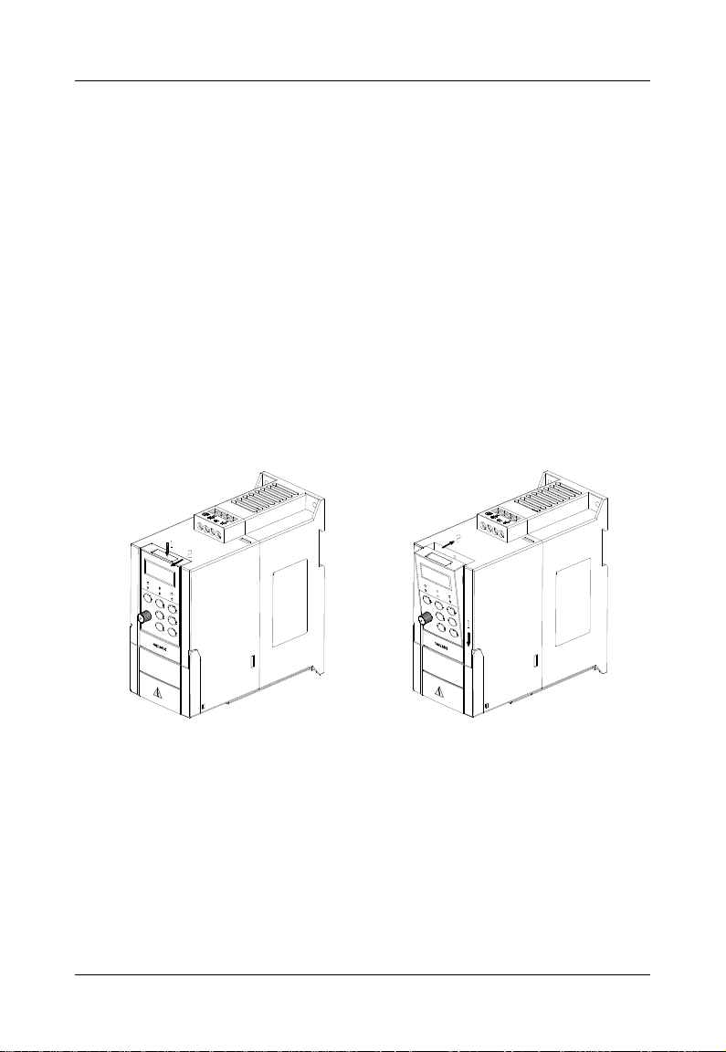
3.3 Remove & Mount the Control Panel and Cover
3.3.1 Remove and Mount the Control Panel
Remove control panel
Press the buckle of control panel as indicated by number "1" in Fig. 3-2 a), then pull
the control panel out to release as indicated by "2".
Mount control panel
Slightly slant the control panel in the direction as indicated by number "1" in Fig. 3-2
b) and align it to clamping port at lower part of control panel bracket, then press it in
as indicated by "2".
When there is a "click" sound, it indicates clamping has been properly made.
a) Remove control panel b) Mount control panel
Fig. 3-2 Remove and mount control panel
3.3.2 Open & Close the Cover
Open the cover
Pull out as indicated by “1” in Fig. 3-3 a) with thumb.
Close the cover
After the completion of wiring, press the cover as indicated by “1” in Fig. 3-3 b).
- 15 -
Chapter 3 Installation and Wiring GK500 User Manual
Model
Breaker
(A)
Contactor
(A)
Brake unit
Power(W)
Resistor(Ω)
GK500-2T0.4B
16
10
70
≥200
GK500-2T0.75B
25
16
70
≥200
GK500-2T1.5B
32
25
260
≥100
GK500-2T2.2B
40
32
260
≥75
GK500-4T0.75B
16
10
300
≥150
GK500-4T1.5B
16
10
450
≥100
GK500-4T2.2B
16
10
600
≥75
GK500-4T3.7B
40
32
600
≥75
When there is a “click” sound, it indicates clamping has been well completed.
a) Open the cover b) Close the cover
Fig. 3-3 Open and close the cover
3.4 Selection of Peripheral Devices
* All models have inbuilt brake chopper, and brake resistors should be sourced. Strictly conform to the
requirement in the form. Failure to comply may result in equipment damage.
Table 3-1 Selection of peripheral devices
- 16 -
GK500 User Manual Chapter 3 Installation and Wiring
WARNING
Only qualified personnel familiar with AC motor drives are allowed to implement
wiring. Failure to comply may result in equipment damage and/or personnel
injury even death.
Wiring should be in strict accordance with this manual, otherwise hazard of
electric shock or equipment damage exists.
Make sure input power supply has been completely disconnected before wiring
operation. Failure to comply will result in personnel injury even death.
All wiring operations and lines should comply with EMC and national and local
industrial safety regulations and/or electrical codes. The conductor diameter
should be in accordance with recommendations of this manual. Otherwise,
hazard of equipment damage, fire, and/or personnel injury exists.
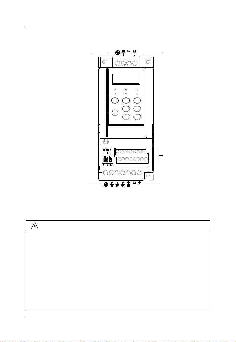
Ground terminal
Main circuit terminal
Ground terminal
Control circuit terminal
Main circuit terminal
3.5 Terminal Configuration
Fig. 3-4 Terminal configuration
3.6 Main Circuit Terminals and Wiring
- 17 -
Chapter 3 Installation and Wiring GK500 User Manual
Since leakage current of the drive may exceed 3.5mA, for safety's sake, the
drive and the motor must be grounded so as to avoid hazard of electric shock.
Be sure to perform wiring in strict accordance with the drive terminal marks.
Never connect three-phase power supply to output terminals U/T1, V/T2 and
W/T3. Failure to comply will result in equipment damage.
Only mount braking resistors at terminals /B1and B2.
Wiring screws and bolts for main circuit terminals must be screwed tightly.
Failure to comply may result in faults and/or equipment damage.
ATTENTION
Signal wires should to the best of possibility be away from main power lines. In
the event that this cannot be ensured, vertical cross arrangement should be
adopted, reducing EMI interference to the signal wires as much as possible.
In case the motor cable exceeds 100m, an appropriate output reactor should be
mounted.
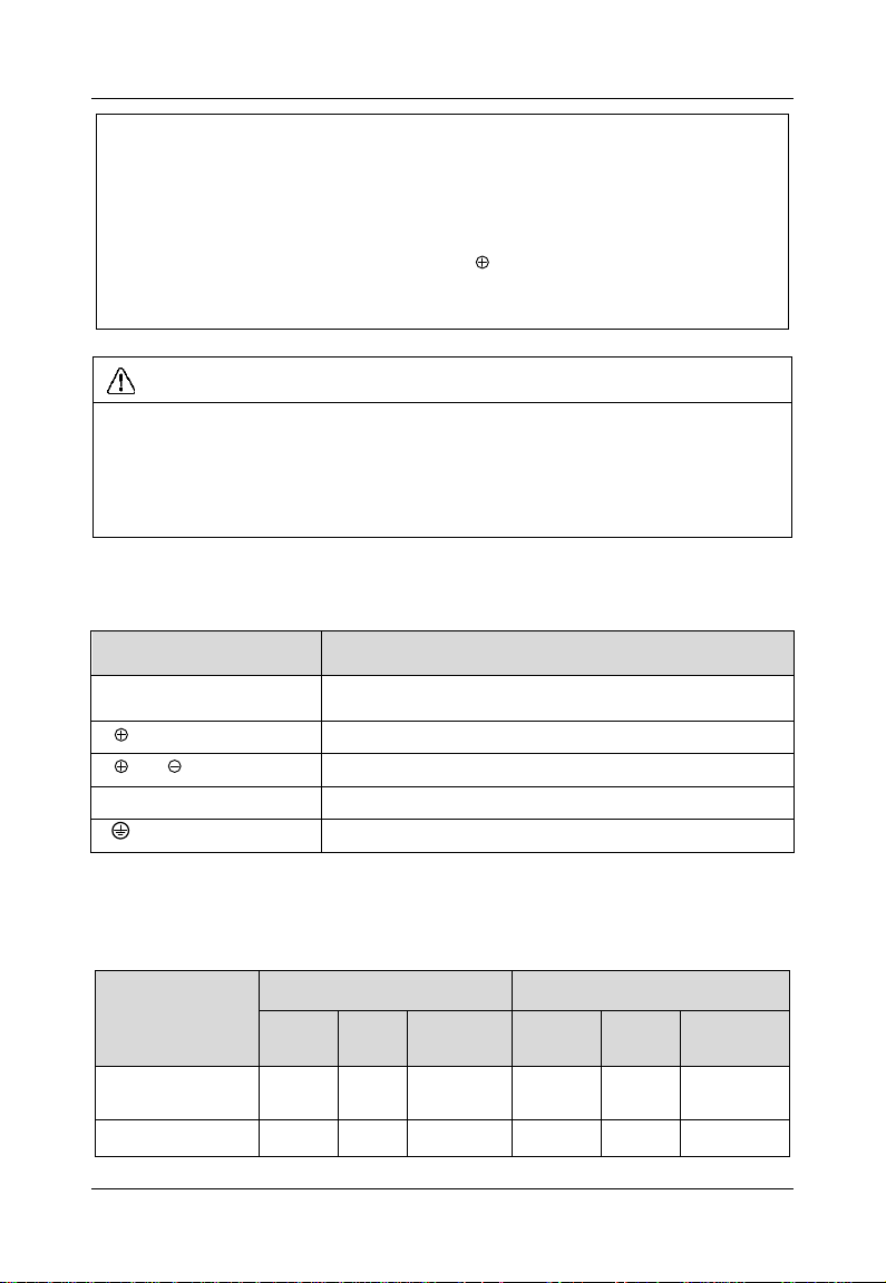
Model
Power terminal
Ground terminal
Cable
(mm2)
Scew
Torque
(kgf.cm)
Cable
(mm2)
Screw
Torque
(kgf.cm)
GK500-2T0.4B
2.5
M3.5
15±0.5
2.5
M3.5
15±0.5
GK500-2T0.75B
2.5
M3.5
15±0.5
2.5
M3.5
15±0.5
Terminal marks
Specification
L1/L、L2、L3/N
Uniphase/Triphase AC power supply input (connect L1/L,
L3/N when the input is uniphase)
/B1、B2
Brake resistor wiring terminals
/B1、
DC power supply input terminals
U/T1、V/T2、W/T3
Triphase AC output terminals
Ground terminal PE
3.6.1 Main Circuit Terminals
3.6.2 Terminal Screw and Wiring Requirement
Table 3-2 Terminal screw and wiring requirement
- 18 -
GK500 User Manual Chapter 3 Installation and Wiring
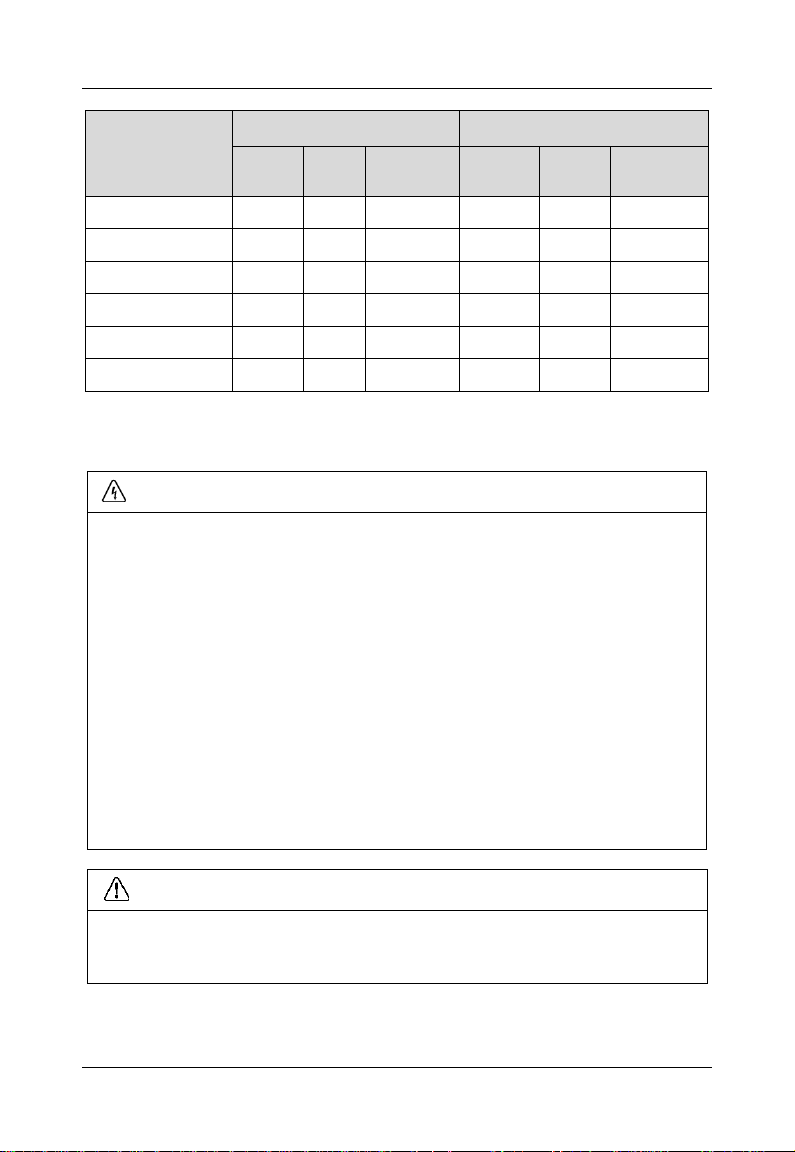
Model
Power terminal
Ground terminal
Cable
(mm2)
Scew
Torque
(kgf.cm)
Cable
(mm2)
Screw
Torque
(kgf.cm)
GK500-2T1.5B
4
M3.5
15±0.5
2.5
M3.5
15±0.5
GK500-2T2.2B
6
M3.5
15±0.5
4
M3.5
15±0.5
GK500-4T0.75B
2.5
M3.5
15±0.5
2.5
M3.5
15±0.5
GK500-4T1.5B
4
M3.5
15±0.5
4
M3.5
15±0.5
GK500-4T2.2B
6
M3.5
15±0.5
4
M3.5
15±0.5
GK500-4T3.7B
6
M3.5
15±0.5
6
M3.5
15±0.5
WARNING
Only qualified personnel familiar with AC motor drives are allowed to implement
wiring. Failure to comply may result in equipment damage and/or personnel
injury even death.
Wiring should be in strict accordance with this manual, otherwise hazard of
electric shock or equipment damage exists.
Make sure input power supply has been completely disconnected before wiring
operation. Failure to comply will result in personnel injury even death.
All wiring operations and lines should comply with EMC and national and local
industrial safety regulations and/or electrical codes. The conductor diameter
should be in accordance with recommendations of this manual. Otherwise,
hazard of equipment damage, fire, and/or personnel injury exists.
Screws or bolts for terminal wiring must be screwed tightly.
AC 220V signal is prohibited from connecting to other terminals than control
terminals RA, RB and RC.
ATTENTION
Signal wires should to the best of possibility be away from main power lines. If
this cannot be ensured, vertical cross arrangement should be adopted, reducing
EMI interference to the signal wires as much as possible.
3.7 Control Terminal Wiring
- 19 -
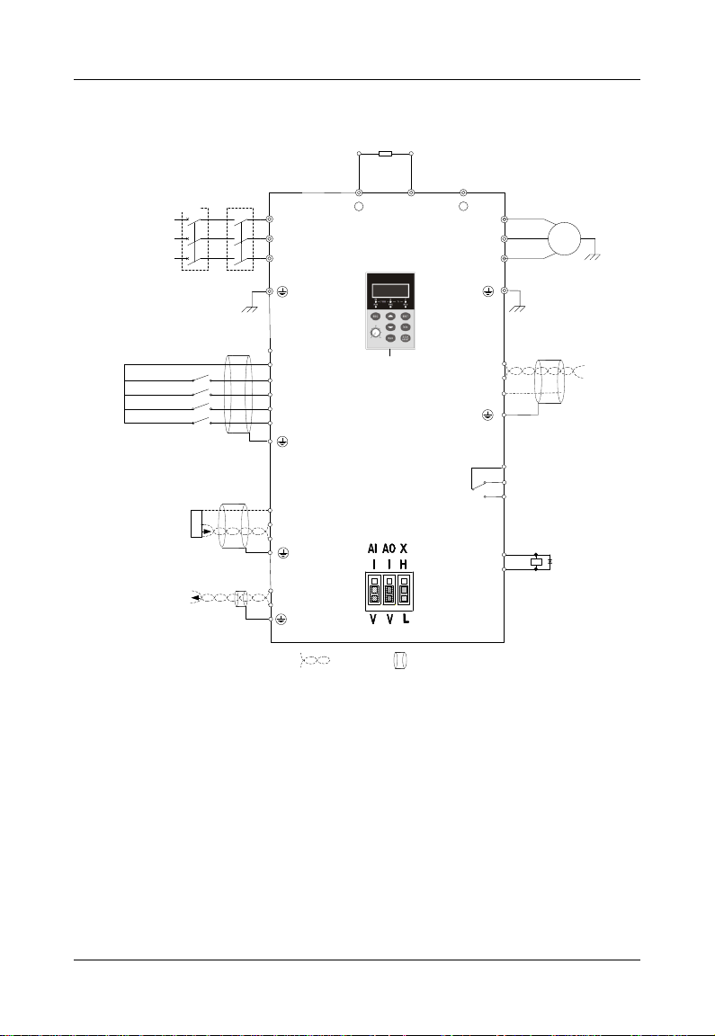
Chapter 3 Installation and Wiring GK500 User Manual
M
Brake Resistor
Motor
Grounding
L1/L
L2
L3/N
U/T1
V/T2
W/T3
Power
supply
grounding
+
/B1
B2
Contactor
AC
Power
Supply
+24V
X1
X2
X3
X4
COM
RA
RB
RC
+24V
Y
+10V
AI
GND
Relay Out 1
250V AC/3A
30V DC/3A
OC Output 1
GK500
Analog In Reference
Voltage
PT
485
MODBUS
COMM
485+
485-
AO
GND
GND
Paired
Cable
Shielded
Cable
Analog In
DC:0~10V/0~20mA
Analog Out
DC:0~10V/0~20mA
Keypad
Digital In 1
Digital In 2
Digital In 3
Digital In 4
-
Braker
Fig. 3-5 Wiring diagram
- 20 -
 Loading...