

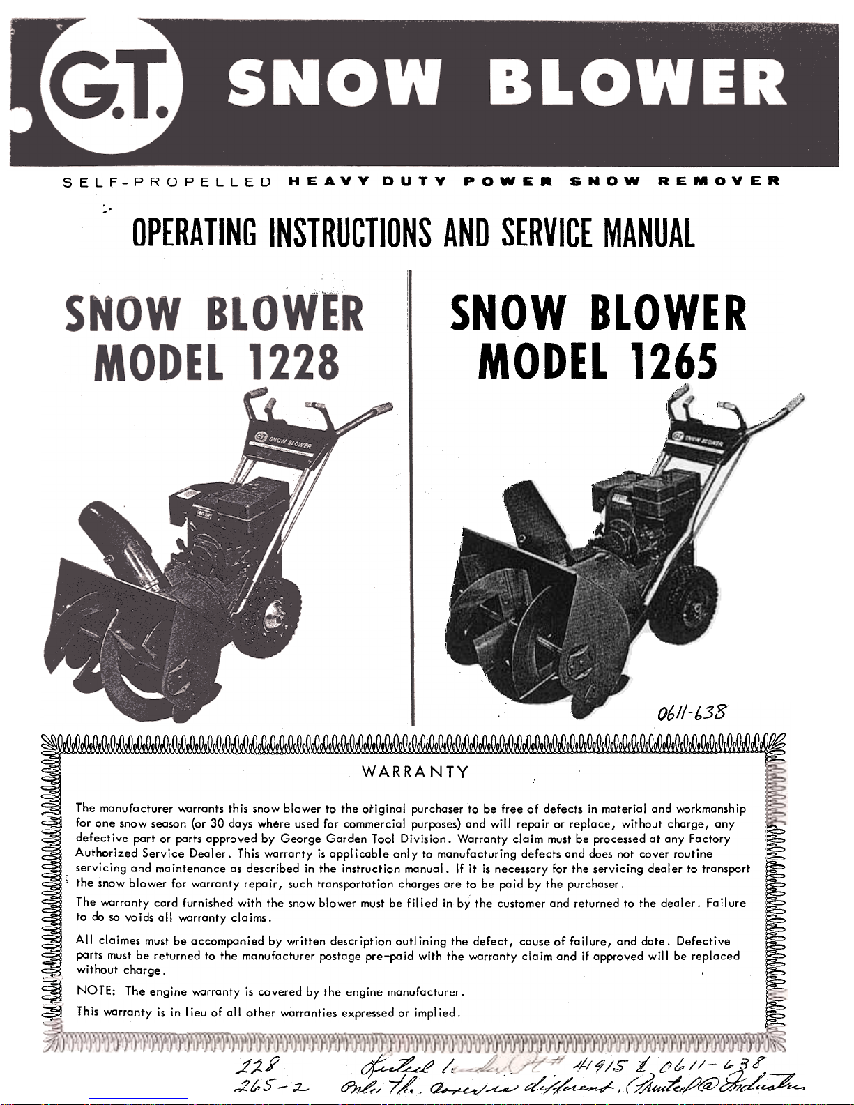
GT 1228 Operating instructions and parts manualvice, 1265 Operating Instructions Manual
SELF-PROPELLED~~~
~
I
I, 06//-b3S
~~~
WARRANTY
The manufacturer v.1:Irrants this snow blower to the original purchaser to be free of defects in material and v.1:Irkmanship
for one snow season (or 30 days where used for commercial purposes) and will repair or replace, without charge, any
defective part or parts approved by George Garden Tool Division. Warranty claim must be processed at any Factory
Authorized Service Dealer. This warranty is applicable only to manufacturing defects and does not cover routine
.servicing and maintenance as described in the instruction manual. If it is necessary for the servicing dealer to transport
..the snaw blower for warranty repa ir, such transportation charges are to be po id by the purchaser.
The v.1:Irranty card furnished with the snow blower must be filled in by the customer and returned to the dealer. Fail ure
to do so voids all v.1:Irranty claims.
All claimes must be accompanied by written description outlining the defect, cause of failure, and date. Defective
parts must be returned to the manufacturer postage pre-pa id with the v.1:Irranty cia im and if approved will be replaced
without charge.
~ NOTE: The engine v.1:Irranty is covered by the engine manufacturer.
~ This v.1:Irranty is in I ieu of all other warranties expressed or impl ied.
~
&J?1~~t:~./~ d/~-~ (~u:Z;;~gj:::z.:c-.
HEAVY DUTY POWER SNOW REMOVER
;..
OPERATING INSTRUCTIONS AND SERVICE MANUAL
.' ~~
~ -SNOW BLOWER
MODEL 1265
( r
)---"" /
~/ I
(- r \ (
=-
"'
\
"""
.)'
;2. Y
,;Z to ~ -;;L-
-
PAGE
PAGE
r
,-over
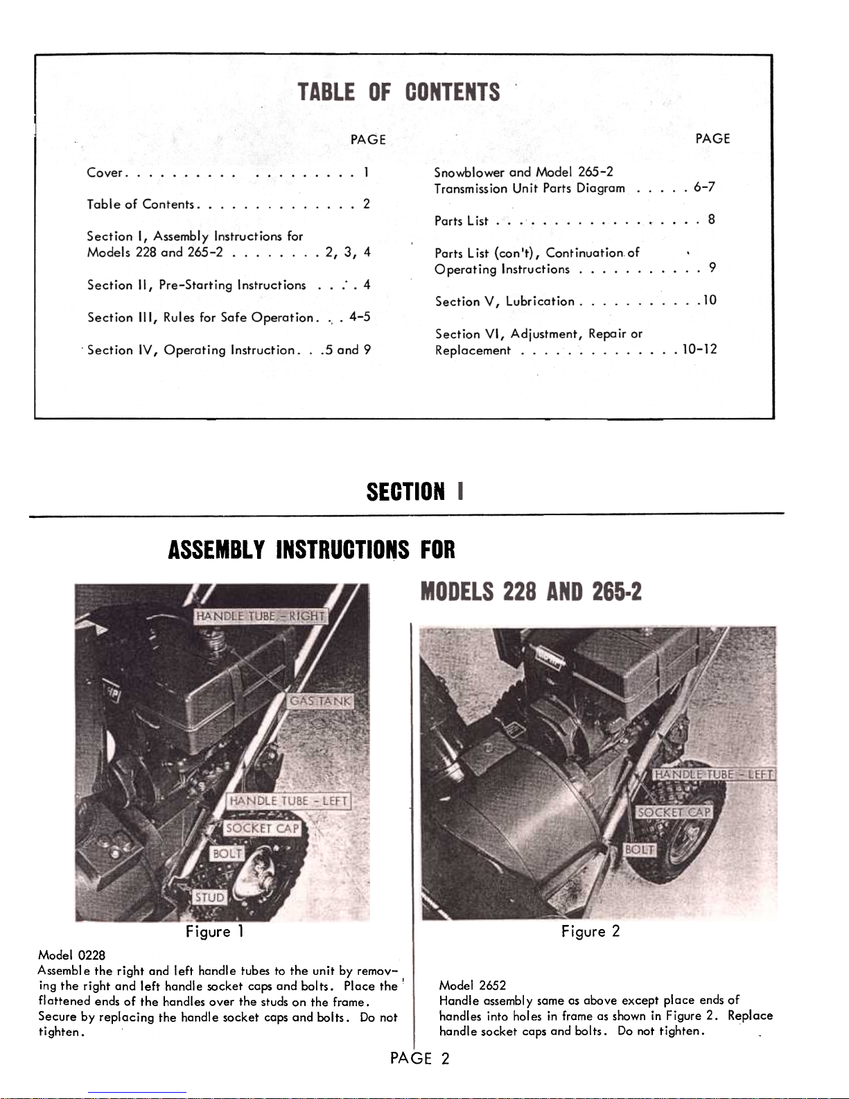
1 Snowblower and Model 265-2
Transmission Unit Parts Diagram. ...
6-7
...2
Table of Contents. ..
8
Parts List.
Section I, Assembly Instructions for
Models 228 and 265-2 2,3,4 Parts List (con't), Continuation of
Operating Instructions.
9
Section II, Pre-Starting Instructions. .: .4
10
Section V f Lubrication. ..
Section III, Rules for Safe Operation. ..4-5
Section VI, Adjustment, Repair or
Replacement.
.5 and 9
.10-12
Section IV I Operating Instruction.
SECTION
ASSEMBLY INSTRUCTIONS FOR
Figure 1
Figure 2
Model 2652
Handle assembly same as above except place ends of
handles into hol es in frame as shown in Figure 2. Replace
handle socket caps and bolts. Do not tighten.
Model 0228
Assemble the right and left handle tubes to the unit by remov-
ing the right and left handle socket caps and bolts. Place the!
flattened ends of the handles over the studs on the frame.
Secure by replacing the handle socket caps and bolts. Do not
tighten.
PAGE 2
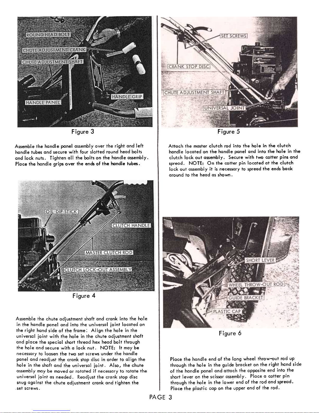
Figure 3 Figure 5
Attach the master clutch rad into the hale in th~ clutch
handle located on the handle panel and into the hale in the
clutch lock aut assembly. Secure with two cotter pins and
spread. NOTE: On the cotter pin located at the clutch
lock out assembly it is necessary to spread the ends back
around to the head as shawn .
Assemble the handle panel assembly over the right and left
handle tubes and secure with four slotted round head bolts
and lock nuts. Tighten all the bolts on the handle assembly.
Place the handle grips over the ends of the handle tubes.
Figure 4
Assemble
the chute adjustment shaft and crank into the hole
in ~he handle ponel and into the universal joint located on
the right hand side of the frame: AI ign the hole in the
universal joint with the hole in the chute adjustment shaft
and place the special short thread hex head bolt through
the hole and secure with a lock nut. NOTE: It may be
necessary to loosen the two set screws under the handle
ponel and readjust th.e crank stop disc in order to al ign the
hole in the shaft and the universal joint. Also, the chute
assembl y may be moved or rotated if necessary to rotate the
universal joint os needed. Readjust the crank stop disc
snug against the chute adjustment crank and tighten the
setscrews.
Figure
6
Place the handle end of the long wheel throw-out rod up
through the hole in the guide bracket on the right hand side
of the handle panel and attach the opposite end into the
short lever on the scissor assembly. Place a cotter pin
through the hole in the lowe~ end of the rod and spread.
Place the plast i c cap on the upper end of the rod.
PAGE
3
SECTION II
PRE. STARTING INSTRUCTIONS
1
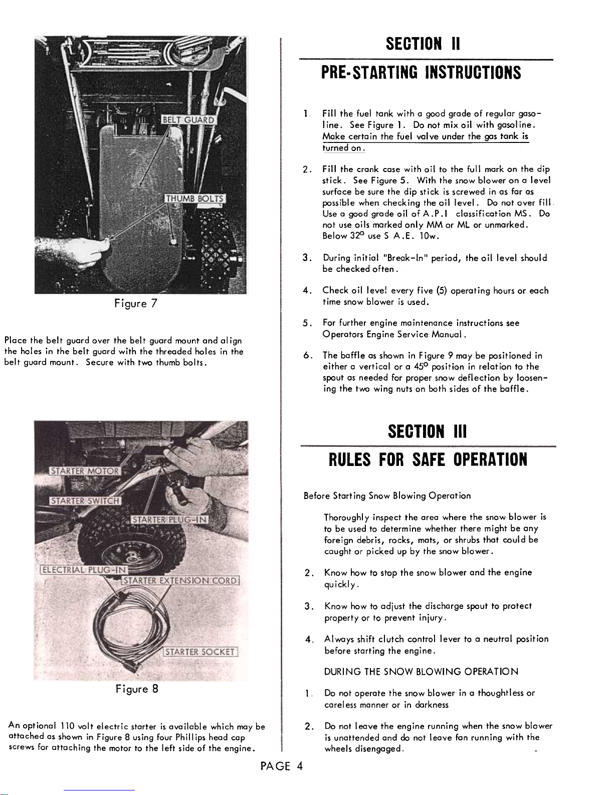
Fill the fuel tank with a good grade of regular gasoline. See Figure 1. Do not mix oil with gasoline.
Make certain the fuel valve under the gas tank is
turned on.
Fill the crank case with ail to the full mark an the dip
stick. See Figure 5. With the snow blower on a level
surface be sure the dip stick is screwed in as for as
possible when checking the oil level. Do not over fill
Use a good grade oil of A.P.I classification MS. Do
not use oils marked only MM or ML or unmarked.
Below 3~ use S A.E. lOw.
2.
3.
During initial "Break-In" period, the oil level should
be checked often.
Check
oil leve! every five (5) operating hours or each
time snow blower is used.
4.
Figure 7
5.
For further engine mointenance instructions see
Operators Engine Service Monual.
Place the belt guard over the belt guard mount and align
the holes in the belt guard with the threaded holes in the
bel t guard mount. Secure with two thumb bol ts.
6.The
baffle as shawn in Figure 9 may be positianed in
either a vertical or a 450 position in relation to the
spout as needed for proper snow deflection by loosen-
ing the two wing nuts on both sides of the baffl e.
SECTION III
RULES FOR SAFE OPERATION
Before Storting Snow Blowing Operation
Thoroughl y inspect the area where the snow blower is
to be used to determine whether there might be any
foreign debris, rocks, mats, or shrubs that could be
caught or picked up by the snow blower.
Know how to stop the snow blower and the engine
quickly.
2.3.
Know how to odjust the discharge spout to protect
property or to prevent injury.
Always shift clutch control lever to a neutral position
before starting the engine.
4.DURING
THE SNOW BLOWING OPERATION
Figure 8
Do not operate the snow blower in a thought I ess orcarel
ess manner or in darkness
1
Do not leave the engine running when the snow blower
is unattended and do not leave fan running with thewheels
disengaged.
An optional 110 volt electric starter is available which may be
attached as shown in Figure 8 us ing four Ph i II ips head cap
screws for attaching the motor to the left side of the engine.
2.PAGE
4
3.
4.
5.6.7.
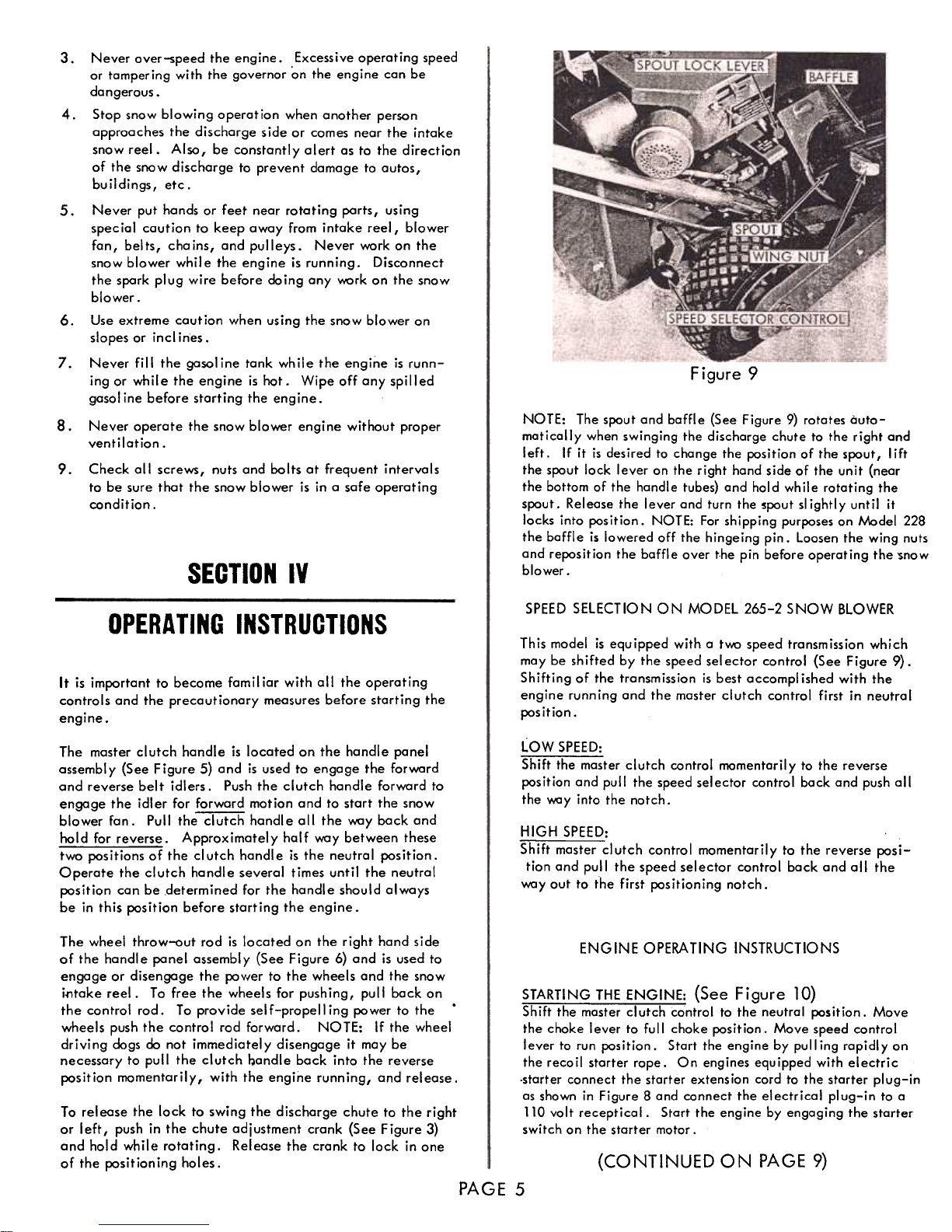
Figure 9
8.
NOTE: The spout and baffle (See Figure 9) rotates automotically when swinging the dischorge chute to the right ond
left. If it is desired to change the position of the spout I lift
the spout lock lever on the right hand side of the unit (near
the bottom of the handle tubes) and hold while rotating thespout.
Rei eose the I ever and turn the spout sl ightl y unt il it
locks into position. NOTE: For shipping purposes on ,'.;.odel 228
the baffle is lowered off the hingeing pin. Loosen the wing nutsand
reposition the baffle over the pin before operating the ~now
blower.
9.
Never over-speed the engine. Excessive operoting speed
or tompering with the governor on the engine con be
dangerous.
Stop snow blowing operation when onother person
opproaches the discharge side or comes near the intake
snow reel. Also, be constantly alert as to the direction
of the snow discharge to prevent damage to autos,
buildings, etc.
Never put hands or feet near rotating parts, using
special caution to keep away from intake reel, blower
fan, belts, chains, and pulleys. Never work on the
snow blower while the engine is running. Disconnect
the spark plug wire before doing ony work on the snow
blower.
Use extreme coution when using the snow blower on
slopes or inclines.
Never fill the gasoline tank while the engine is runn-
ing or while the engine is hot. Wipe off any spilled
gasoline before starting the engine.
Never operate the snow blower engine without proper
ventilation.
Check all screws, nuts and bolts at frequent intervals
to be sure thot the snow blower is in a safe operating
condition.
SECTION IV
SPEED
SELECTION ON MODEL 265-2 SNOW BLOWER
OPERATING
INSTRUCTIONS
This model is equipped with a tv.\:> speed transmission which
moy be shifted by the speed selector control (See Figure 9).
Shifting of the tronsmission is best accompl ished with the
engine running and the master clutch control first in neutral
position.
It is important to became familiar with all the operating
controls and the precautionary measures before starting the
engine.
The master clutch handle is located on the handle panel
assembly (See Figure 5) and is used to engage the forward
and reverse belt idlers. Push the clutch handle forward to
engage the idl er for forward motion and to start the snow
blower fan. Pull the clutch handle all the way back and
hold for reverse. Approximately half way between these
twa positions of the clutch handle is the neutral position.
Operate the clutch handle several times until the neutral
position can be determined for the handle should always
be in this position before starting the engine.
LOW SPEED:
Shift the master clutch control momentarily to the reverse
position ond pull the speed selector control bock and push all
the way into the notch.
HIGH SPEED:
Shift master clutch control momentarily to the reverse posi-
tion and pull the speed selector control back and all the
way out to the first positioning notch.
The wheel throw-out rod is located on the right hand side
of the handl e panel assembl y (See Figure 6) and is used to
engage or disengage the pav{er to the wheels and the snow
i~take reel. To free the wheels for pushing, pull back on
the control rod. To provide self-propelling pawer to the'
wheels push the control rod forward. NOTE: If the wheel
driving dogs do not immediately disengage it may be
necessary to pull the clutch ~andle back into the reverse
position momentarily, with the engine running, and release.
ENGINE OPERATING INSTRUCTIONS
STARTING THE ENGINE: (See Figure 10)
To release the lock to swing the discharge chute to the right
or left, push in the chute adjustment crank (See Figure 3)
and hold while rotating. Release the crank to lock in one
of the positioning holes. (CONTINUED ON PAGE 9)
PAGE 5
Shift the master clutch control to the neutral position. Move
the choke lever to full choke position. Move speed control
lever to run position. Start the engine by pull ing rapidly on
the recoil starter rope. On engines equipped with electric
-starter connect the starter extens ion cord to the starter pi ug-in
as shown in Figure 8 and connect the electrical plug-in to a
110 volt receptical. Start the engine by engaging the starter
switch on the starter motor.
 Loading...