

GSW SUPERFLUE POWER VENTED GAS FIRED WATER HEATER, SUPERFLUE Installation And Operating Instructions Manual
GSW WATER HEATING COMPANY
599 HILL ST. WEST, FERGUS, ONTARIO N1M 2X1
CANADA
“SUPERFLUE”
®
POWER VENTED GAS FIRED WATER HEATER
INSTALLATION AND OPERATING INSTRUCTIONS
Read these instructions
WARNING: If the information in these instructions is
- Installation and service must be performed by a
not followed exactly, a fire or explosion may result
- Do not store or use gasoline or other flammable
WARNING: Improper installation, adjustment,
qualified installer, or the gas supplier.
alteration, service, or maintenance can cause injury or
causing property damage, personal injury or death.
vapors and liquids in the vicinity of this or any
property damage. Refer to this manual. For
other appliance.
assistance or additional information, consult a
- WHAT TO DO IF YOU SMELL GAS
qualified installer, service agency, or the gas supplier.
· Do not try to light any appliance.
· Do not touch any electrical switch; do not use any
phone in your building.
· Immediately call your gas supplier from a neighbor’s
phone. Follow the gas supplier’s instructions.
· If you cannot reach your gas supplier, call the fire
department.
thoroughly before starting
TABLE OF CONTENTS
I) Introduction .....................................................................................................................................2
II) Air Requirement.................................................................................................................................4
III) Venting ............................................................................................................................................7
IV) Water Piping..................................................................................................................................10
V) Gas Piping...................................................................................................................................... 10
VI) First Lighting.....................................................................................................................................................................11
VII) Service And Maintenance ................................................................................................................................................14
VIII) Combo Heating..................................................................................................................................................................16
IX) Troubleshooting.............................................................................................................................. 18
X) Warranty...................................................................................................................................... 19
This Manual Applies to Electronic Ignition Power Vented Water Heater
Check The Specific Venting Label On The Water Heater For Details
PLEASE RETAIN THESE INSTRUCTIONS IN A SAFE LOCATION FOR FUTURE REFERENCE
PART NO. 50000 REV. ¬ (FF-06-99)
-1-

I) Introduction
We thank you for choosing a GSW/ John Wood Water Heater.
Your satisfaction with this product is very important to us.
All electrical connections shall be in accordance with the latest
edition of the Canadian Electrical Code CSA C22⋅1 Part 1.
This gas-fired water heater has been developed to produce
potable hot water and may also be used in combination with space
heating applications. The “Superflue” series is designed to vent
the products of combustion (flue gases) horizontally through an
exterior wall or vertically through the roof using an integrated
blower assembly and plastic piping, without the need for a
conventional chimney.
Important Consumer Notice
These instructions have been written for the proper installation,
safe operation and maintenance of this water heater.
It is your responsibility to ensure that your water heater is
properly installed and cared for. FAILURE TO FOLLOW
THE INSTRUCTIONS IN THIS MANUAL MAY
RESULT IN SERIOUS BODILY INJURY AND /OR
PROPERTY DAMAGE. THOROUGHLY READ ALL
INSTRUCTIONS before you attempt to install or operate this
heater.
Installation and service require trade knowledge in the area of
plumbing, electricity, venting, air supply and gas supply. If you
lack these skills or do not understand these instructions, enlist
the help of a qualified professional.
GSW Water Heating Company, the manufacturer of this water
heater, cannot be held liable for those damages caused by
improper installation, sizing or failure to comply with these
instructions.
Approvals
This water heater has been certified for operation using natural
gas or propane gas fuel by the Canadian Gas Association (CGA)
and design-certified by the American Gas Association
Laboratories (AGA) through International Approval Services Inc.
This heater is approved to provide potable hot water or when
combined with a suitably-sized fan coil, baseboard heater, etc., to
provide both space heating and domestic hot water.
Installation Code Requirements
Canadian Installations
In addition to the installation instructions found in this manual,
the heater shall be installed in accordance with the latest edition
of CAN/CGA B149.1, B149.2 installation codes and/or any local
codes. These shall be carefully followed in all cases. Authorities
having jurisdiction shall be consulted before installations are
made.
U.S. Installations
In addition to the installation instructions found in this manual,
the heater shall be installed in accordance with the latest edition
of the National Fuel Code ANSI Z223⋅1 (NFPA 54) and/or any
local codes. These shall be carefully followed in all cases.
Authorities having jurisdiction shall be consulted before
installations are made.
Important: All supply equipment, installation, Approvals,
permits, inspections, etc. are the responsibility of the owner of
this water heater. Consult your local authorities for regulations
specific to your area.
Relief Valves (T&P)
All heaters must be installed with a proper temperature and
pressure relief valve. These valves must be certified as meeting
the requirements for Relief Valves and Automatic Gas Shut-Off
Devices for Hot Water Supply Systems, ANSI Z21⋅22 in the
United States. When in Canada, the Standard for Temperature,
Pressure, Temperature and Pressure Relief and Vacuum Relief
CAN 4⋅4 is required.
Backflow Prevention
Certain jurisdictions may require the installation of a backflow
device (e.g., check valve) in the water supply line. Such a device
will require the use of a system expansion tank of adequate size
to control the thermal expansion generated during the heating
cycle. Consult your water supplier or local plumbing authority.
Important: The supply water meter may have a built-in check
valve device. Contact your local water authority.
Safety Warnings
Ø Water Heaters are heat-producing appliances. To avoid
damage or injury, no materials shall be stored against the
heater and provision shall be made to prevent unauthorized
contact (e.g. children).
FOR YOUR SAFETY, DO NOT STORE OR
USE GASOLINE OR OTHER FLAMMABLE,
COMBUSTIBLE OR CORROSIVE VAPORS
OR LIQUIDS IN THE VICINITY OF THIS
HEATER OR ANY OTHER APPLIANCE.
Ø Hot water produced by this appliance can cause severe burns
due to scalding. The hazard is increased for young children,
-2-

the aged, or the disabled where water temperatures exceed
125° F (52°C).
Use anti-scald valves in the hot water system to reduce the
risk of scalding at points of use such as lavatories, sinks and
bathing facilities. Such precautions must be followed when
this heater is operated in combination with dishwashing or
space heating applications.
Ø As with all fuel burning equipment, this heater requires an
adequate supply of air for combustion and ventilation. An
insufficient air supply can result in poor combustion or the
recirculation of the exhaust flue gases. Such a condition can
cause sooting or present a fire hazard, which may result in
serious bodily harm or death from asphyxiation.
MAKE SURE THE FLOW OF COMBUSTION
AND VENTILATION AIR IS NOT
RESTRICTED.
Ø If this water heater has been exposed to flooding, freezing,
fire or any unusual condition, do not put it into operation until
it has been inspected and approved by a qualified
professional. THESE CONDITIONS CAN RESULT
IN UNSEEN INTERNAL DAMAGE and are not
subject to warranty coverage.
Safety Warnings
Ø There is a risk in using fuel-burning appliances such as water
heaters. Areas that may not be suitable for water heater
installation include those where flammable liquids, gasoline,
solvents, adhesives, etc., or engine-driven equipment or
vehicles are stored, operated or repaired. Due to the nature
of air movement, flammable vapors can be carried some
distance from the point of storage. The gas-fired water
heater, pilot or main burner flame can ignite these vapors
causing a flashback fire or explosion which may result in
serious personal injury or death, as well as severe property
damage.
(softener salt) or other process chemicals are typical of
compounds which are potentially corrosive.
Ø Products of this type should not be stored near the heater.
Air containing these chemicals should not be used as supply
to the heater. If necessary, uncontaminated air shall be
obtained from remote or outside sources.
Ø HYDROGEN GAS CAN BE PRODUCED IN A
HOT WATER SYSTEM. THIS CAN BE
PROBLEMATIC IN SYSTEMS WITH LONG
STANDBY PERIODS. HYDROGEN GAS IS
EXTREMELY FLAMMABLE To reduce the risk of
injury under these conditions, it is recommended that the hot
water faucet be opened for several minutes at the kitchen
sink before using any electrical appliance connected to the
hot water system. If hydrogen is present, there will probably
be an unusual sound, such as air escaping through the pipe as
the water begins to flow. THERE SHOULD BE NO
SMOKING, OR OPEN FLAME NEAR THE
FAUCET AT THE TIME THAT IT IS OPEN.
INSTALLATION INSTRUCTIONS
NOTICE
Before installing this water heater consideration and planning
must be given to the following details:
Ø Heater location. The vent blower can create air noise. Do not
install near sleeping area, in a bedroom or bathroom;
Ø Location of the outside vent terminal; See “Venting” p. 7.
Ø Routing and support of the vent piping; Figure 5 page 8.
Ø How and where to obtain combustion and ventilation air
supply; See “Air Requirements” page 4.
Ø Position of water supply and placement of water piping for
hot and cold water; See “Water Connections” page 10.
Ø Access for gas supply, electrical power, floor drain and
service. See “Gas Service” pages 10 and 11.
If installation in a garage or shed is the only option, it is
recommended that the water heater be elevated a minimum
of 18" (45 cm) above the floor level. This may reduce BUT
NOT ELIMINATE the risk of flammable vapors being
ignited. Such installations must be protected from impact or
physical damage caused from moving equipment or vehicles.
CHECK LOCAL CODES!
Ø Exposure to air borne chemicals can cause severe corrosion
to the water heater and damage to the venting parts. Air
containing vapors from cleaning solvents, pool chemicals,
refrigerator or air conditioning refrigerants, laundry
detergents or bleaches, waxes, spray can propellants, dry
cleaning, photo processing liquids, calcium and sodium chloride
NOTICE
REVIEW SAFETY WARNINGS FOUND IN THE
FRONT OF THIS MANUAL BEFORE PROCEEDING.
Location and Clearances
Locate the water heater such that all controls are easily
accessible. We recommend that 24" (0.6 m) in front of the
heater and 34" (0.9 m) above be maintained for serviceability.
Ensure that the water heater is level. See Figure 1. Page 1. and
Figure 2 page 4.
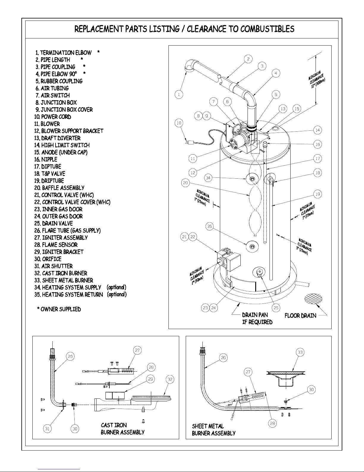
This heater is designed to safely operate with the following
minimum clearances to combustibles.
Front 2" (50 mm) Sides and Rear1" (25 mm)
Top 12" (305 mm) Plastic Vent Piping 0" (0.0 mm)
-3-

Locate near a floor drain and in an area where leakage of the tank
or water piping will not result in damaging adjacent areas or lower
floors of the structure. Where such a location is not available, a
suitable drain pan must be installed under this water heater. This
pan shall be 1½ “ (40 mm) deep and a diameter that is a minimum
of 2" (50 mm) greater than the diameter of the water heater. A
suitable pipe properly connected to an adjacent floor drain shall
be provided.
This heater may be installed in a closet or alcove and is certified
for operation on a combustible floor.
WARNING
Do not install directly on carpet. Instead, place the water heater
on a metal or wood panel extending a minimum of 3" (75 mm) from
all sides. In alcoves or closets, cover the carpet completely.
Ensure that this panel is capable of supporting the weight of this
heater when filled with water.
FAILURE TO PROPERLY INSTALL THIS HEATER
MAY RESULT IN A FIRE HAZARD.
II) AIR REQUIREMENTS
General.
Ø An adequate air supply shall be provided for
combustion and ventilation of this water
heater. An insufficient supply can result in
poor combustion and possible sooting of the
burner, combustion chamber or flue
passageway. This may present a potential
fire hazard or could create a serious health
hazard by producing carbon monoxide.
Where an exhaust fan or any other air consuming appliance (Eg.
Clothes dryer, furnace, etc.) is installed in the same space as the
water heater, sufficient air openings must be available to provide
fresh air when all appliances are operating simultaneously.
The area in which the heater is located is classified as either “an
unconfined space” or “a confined space.”
An unconfined space is defined as a space having a volume not
less than 50 cubic feet per 1000 BTU/hour (4.8 cubic meters per
kilowatt) of combined input rating of all appliances using the
space. Adjacent open rooms may be included as part of the
unconfined space. There shall be no closeable doors between
these rooms. An example of this is an open basement.
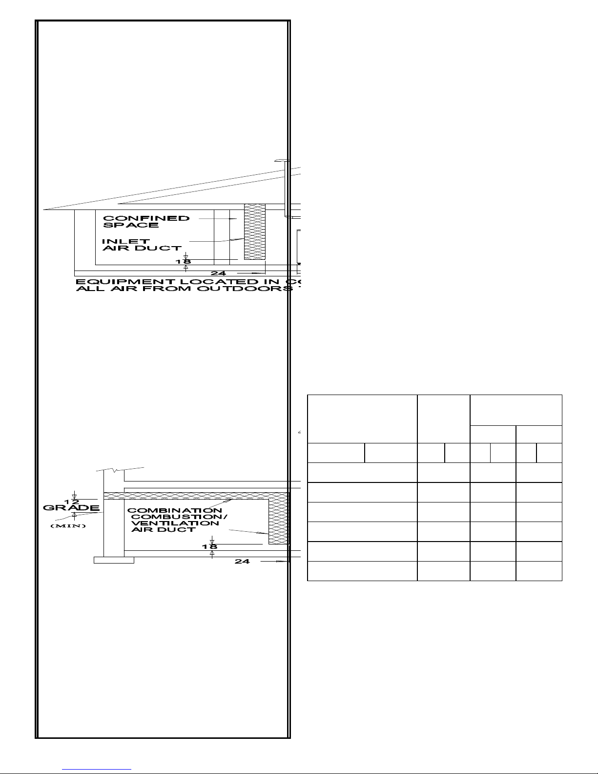
A confined space is one smaller than described above. Air shall
be supplied through permanent openings as described in Figures
3 and 4. At no time shall an air opening have a dimension of less
than 3" (75 mm) and at no time shall any top opening be lower
than the top of the water heater.
For buildings that are not well sealed (do not have tight fitting
doors and windows) natural air infiltration may provide sufficient
air required for combustion and ventilation. For buildings using
tight construction (newer and renovated structures), the air
supply shall be introduced from the outdoors, regardless of
whether the space is confined or unconfined.
Combustion Air “Supply” Ducts
Air supply ducts shall be of galvanized steel or equivalent
corrosion resistant material. A single air duct may not be
substituted when required for upper and lower air openings.
Horizontal upper combustion air ducts shall not slope downward
toward the air inlet.
Louvers and Grills
Openings for air supply ducts must provide free unobstructed air
movement. Louver and grill openings must be sized to ensure that
the FREE OPEN AREA is never less than the area of the air
duct.
-4-
Air Requirements for Canadian
1B 2
Installations
Canadian Codes allow for the use of a single air supply source.
Canadian customers and authorities having jurisdiction may use
the sizing listed in Table 1. Check Local Codes.
When using a single air supply, the duct shall terminate within 1
foot (30 cm) above and within 2 feet (60 cm) horizontally from
the burner level of the appliance having the largest input as shown
in Figure 3 (b), (c) and (d).
An opening shall be located neither more than 18 inches (450
mm), nor less than 6 inches (150 mm), above floor level. See
Figure 3 (b), (c) and (d).
Two permanent openings shall be provided connecting the
confined space (e.g., closet/small room) with the unconfined
space. Each opening shall have a free area of one square inch per
1,000 BTU/hour input (5.5 cm²/kW) of all appliances in the
confined space. The top opening shall commence within 12" (30
cm) of the top of space and the bottom opening shall commence
within 12" (30 cm) of the bottom of the enclosure. See Figure 3
(a).
All exterior vent openings are to be clear of snow levels.
Table 1
Combined Input of All
Appliances in Confined
Space*
BTU/hr (KW/hr) In.2cm2In. mm In. mm
25,000 (8) 7(45) 3(75) 4(100)
50,000 (15) 7(45) 3(75) 4(100)
75,000 (23) 11 (70) 4(100) 5(125)
100,000 (30) 14(90) 4(100) 5(125)
125,000 (37) 18(120) 5(125) 6(150)
150,000 (45) 22(140) 5(125) 6(150)
1 Maximum length of ducts in column A is 20 equivalent feet (6.1
meters)
2 Maximum length of ducts in column B is 50 equivalent feet (15.2
meters)
* All appliances refers to and includes those appliances using the
same air source. e.g. Water heater, furnace, boiler, clothe dryer, etc.
Required
Free Area
Acceptable Round
Duct Size Diameter
A
-5-
 Loading...