

GSW Residential Electric Water Heater User Manual

Residential Electric
Water Heater
Installation
Instructions and
Use & Care Guide
To obtain technical, warranty or service assistance during or
after the installation of this water heater, call toll free
1-888-GSW-TECH (1-888-479-8324)
When calling for assistance, please have the following
information ready:
1. Model number
2. Catalogue number
3. Serial number
4. Date of installation
5. Place of Purchase
Table of Contents Page
Water Heater Safety ............................................................................... 2
Installing Your Water Heater .................................................................3-8
Unpacking Instructions ............................................................... 3
Location Requirements ............................................................... 4
Electrical Requirements .............................................................. 5
Water System Piping ................................................................... 6
Installation Checklist ................................................................... 8
Operating Your Water Heater .............................................................9-10
Water Temperature Regulation ................................................... 9
Operational Conditions ............................................................. 10
Maintenance of Your Water Heater .................................................. 11-13
Troubleshooting Chart ........................................................................... 14
Repair Parts Illustration ......................................................................... 15
Warranty ................................................................................................ 17
REV. B (08-06)
22451
WATER HEATER SAFETY
Your safety and the safety of others are very important.
We have provided many important safety messages in this manual and on your appliance. Always read and obey all
safety messages.
This is the safety alert symbol.
This symbol alerts you to potential hazards that can kill or hurt you and others.
All safety messages will follow the safety alert symbol and either the word “DANGER” or
“WARNING.” These words mean:
You can be killed or seriously injured if you don’t
DANGER
WARNING
All safety messages will tell you what the potential hazard is, tell you how to reduce the chance of injury, and tell you
what can happen if the instructions are not followed.
Important Safety Instructions
CAUTION: Hydrogen gas is produced in a hot water system served by this heater that has not been used for a long
period of time (2 weeks or more). Hydrogen gas is extremely fl ammable. To reduce the risk of injury under these
conditions, it is recommended that the hot water faucet be opened for several minutes at the kitchen sink before
using any electrical appliance connected to the hot water system. When hydrogen is present, there will probably be
an unusual sound such as air escaping through the pipe as the water begins to fl ow. There should be no smoking or
open fl ame near the faucet at the time it is open.
immediately follow instructions.
You can be killed or seriously injured if you don’t
follow instructions.
2

INSTALLING YOUR WATER HEATER
Consumer Information
This water heater should be installed in accordance with
the local code authority having jurisdiction, the power
company or electric utility, and this installation manual.
In the absence of local code requirements, follow the
regulations set forth in the latest edition of
“Canadian Electrical Code (CAN/CSA C22.1), Part I”.
This is available from the following:
Canadian Standards Association,
5060 Spectrum Way,
Mississauga, Ontario, Canada,
L4W 5N6
or
“National Electrical Code” (NFPA 70).
This is available from:
American National Standards Institute,
25 West 43rd Street,
New York, NY 10036
Check your phone listings for the local authorities having
jurisdiction over your installation.
Consumer Responsibilities
This manual has been prepared to acquaint you with the
installation, operation and maintenance of your electric
water heater and to provide important safety information in
these areas.
We urge you to read all of the instructions thoroughly
before attempting the installation or operation of this water
heater. This manual should be kept for future reference.
The manufacturer of this water heater will not be liable
for any damages caused by failure to comply with the
installation and operating instructions outlined in this
manual.
If you lack the necessary skills required to properly install
this water heater or you have diffi culty following the
directions, you should not proceed but have a qualifi ed
person perform the installation of this water heater.
Examples of a qualified person include: licensed plumbers,
authorized gas company personnel, and authorized
service personnel.
A rating plate identifying your water heater can be found on
the side of the water heater. When referring to your water
heater always have the information listed on the rating plate
readily available.
Retain your original receipt as proof of purchase.
Unpacking the Water Heater
Removing Packaging Materials
IMPORTANT: Do not remove any permanent instructions,
labels, or the data label from either the outside of the water
heater or on the inside of water heater panels.
• Remove exterior packaging and place installation
components aside.
• Inspect all parts for damage prior to installation and
start-up.
• Completely read all instructions before attempting to
assemble and install this product.
• After installation, dispose of/recycle all packaging
materials.
3
Location Requirements
Site location
Select a location near the point of use. It must be installed
indoors and in a vertical position with water inlet and outlet
connections facing upwards and easily accessible.
The water heater should be located in an area not subject
to freezing temperatures. Water heaters located in
unconditioned spaces (i.e., attics, basements, etc.) May
require the water piping and drain piping to be insulated
to protect against freezing. The controls must be easily
accessible for operation and service.
This water heater is designed to be used for potable water
heating only.
This water heater does not have suffi cient capacity for use
with a spa or hot tub.
This water heater is not suitable for space heating.
Selected location must provide adequate clearances for
removing the front cover in order to service parts such as
the thermostat, element, temperature sensor, anode, high
limit reset, operating the relief valve, etc.
The water heater should be located so it is not subject to
physical damage by moving vehicles or area fl ooding.
The selected wall or cabinet must be capable of supporting
at least two times the weight of the water heater when fi lled
with water.
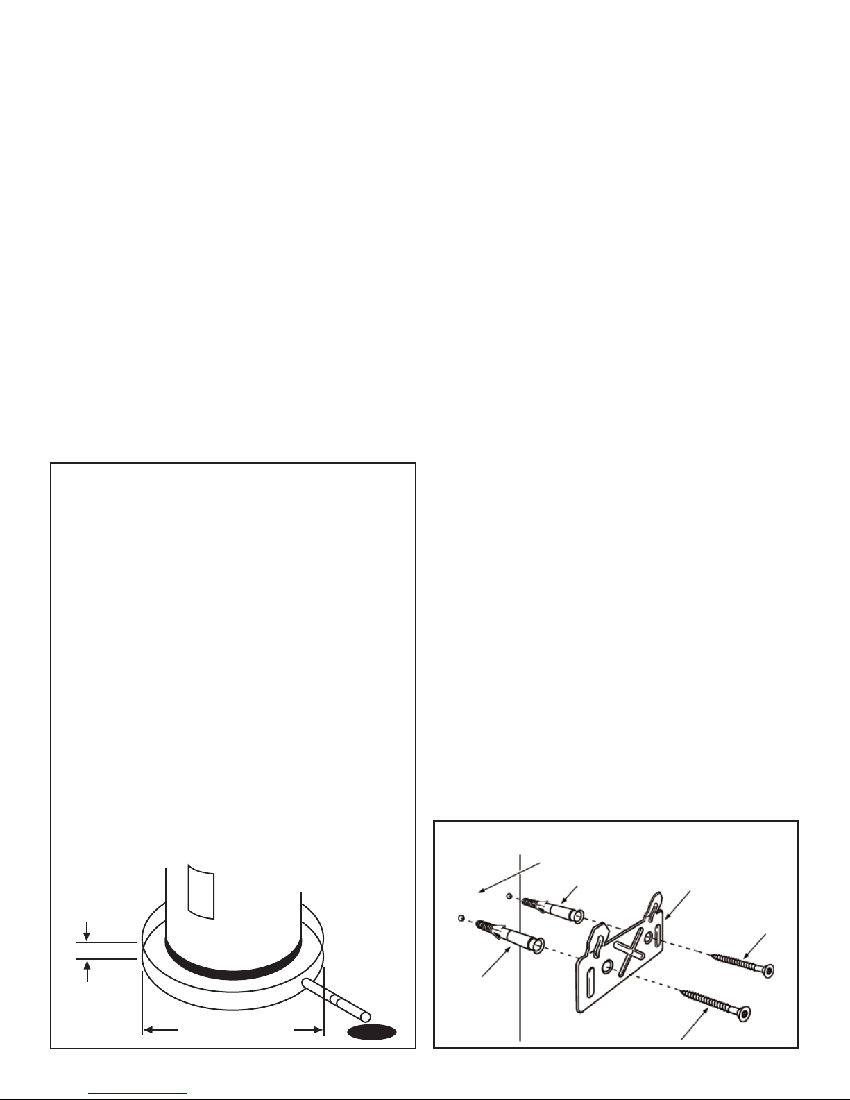
Mounting
NOTE: The water heater must be mounted to avoid moving.
1. Place the mounting bracket (see Figure 1) against the
mounting surface where you intend to install the unit.
The holes must be horizontally level, and the hooks
must be facing upward and angled away from the wall.
2. Verify that the mounting hardware and mounting
surface used to attach the bracket are strong enough to
support the weight of the fi lled water heater and piping.
3. Install the mounting hardware per instructions provided
with the hardware.
4. Align the two mounting slots on the water heater with
the hooks on the mounting bracket and seat the water
heater onto the bracket.
IMPORTANT: The water heater should be located in an
area where leakage of the tank or connections will not
result in damage to the area adjacent to the water heater
or to lower floors of the structure. Due to the normal
corrosive action of the water, the tank will eventually
leak after an extended period of time. Also any external
plumbing leak, including those from improper installation,
may cause early failure of the tank due to corrosion if
not repaired. If the owner/operator is uncomfortable with
making the repair a qualified person should be contacted.
A suitable drain pan should be installed under the water
heater as shown below, to help protect the property from
damage which may occur from condensate formation or
leaks in the piping connections or tank. The pan must
limit the water level to a maximum depth of 64mm (21/2 in.) and be 50mm (2 in.) wider than the heater and
piped to an adequate drain. Locate the water heater
near a suitable indoor drain. Outside drains are subject
to freezing temperatures which can obstruct the drain
line. The piping should be at least 19mm (3/4 in.) ID and
pitched for proper drainage. Under no circumstance will
the manufacturer or seller of this water heater be held
liable for any water damage which is caused by your
failure to follow these instructions.
Figure 1
Mounting Bracket
Details
WALL
ANCHOR
(IF REQUIRED)
WALL MOUNTING
BRACKET
2-1/2 in. (64mm)
Maximum
At least 2 in. (50mm) greater
than the diameter of the
water heater
4
Pipe to
adequate
drain
LAG SCREW
ANCHOR
(IF REQUIRED)
LAG SCREW
Electrical Requirements
WARNING
Electric Shock Hazard
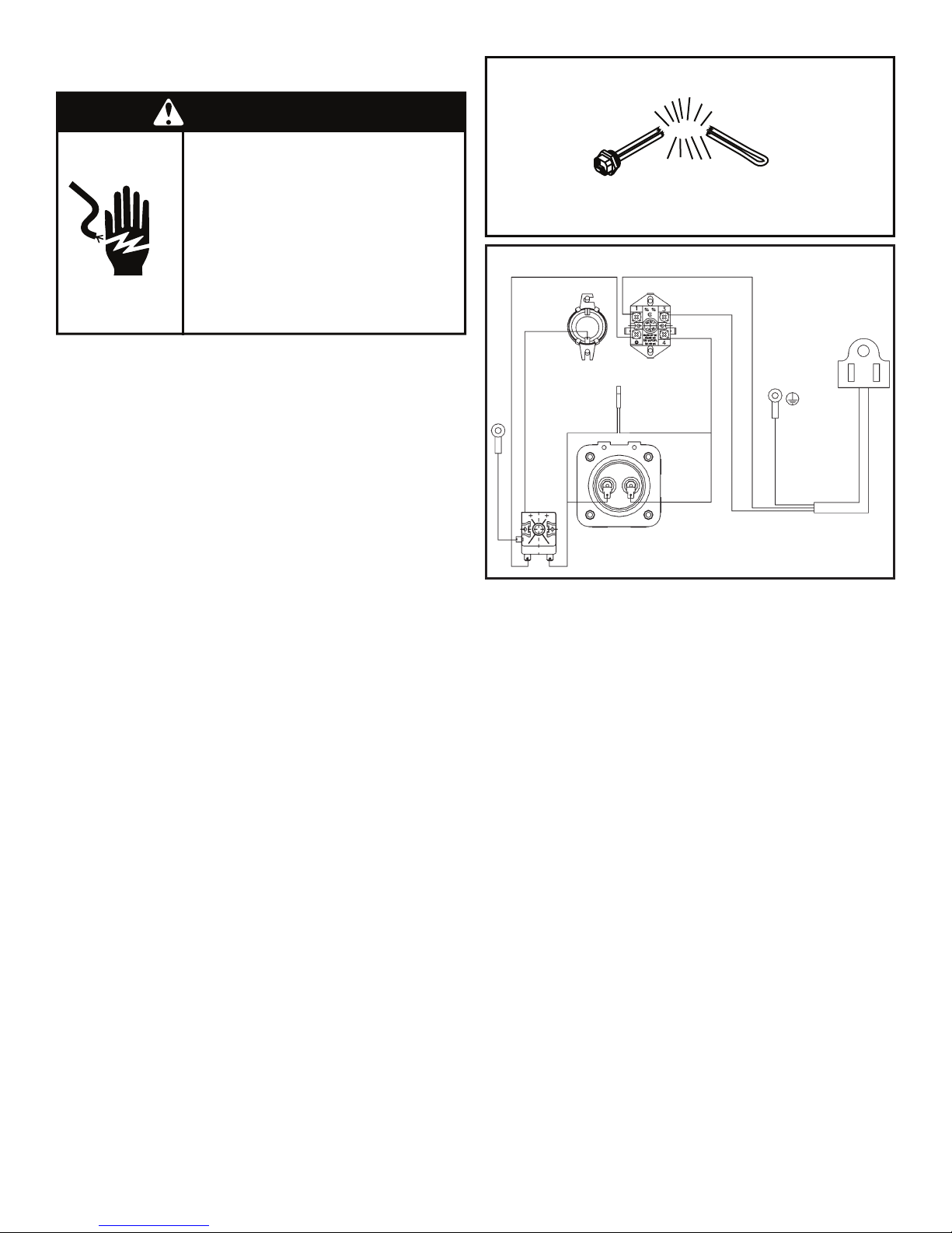
Figure 2
Heating Element
Disconnect power before
servicing.
Replace all parts and panels
before operating.
Failure to do so can result in
death or electrical shock.
This water heater is equipped for one type voltage only.
Check the rating plate on the side of the water heater for
the correct voltage. DO NOT use this water heater with
any voltage other than the one shown on the rating plate.
Failure to use the correct voltage can cause problems
which can result in DEATH, SERIOUS BODILY INJURY,
OR PROPERTY DAMAGE. If you have any questions or
doubts consult your electric company.
If you lack the necessary skills required to properly install
the electrical wiring to this water heater, do not proceed but
have a qualifi ed electrician perform the installation.
When making the electrical connections, always make
sure:
• The electrical supply has the proper overload fuse or
breaker protection.
• Wire sizes and connections comply with all applicable
codes.
• Wiring enclosed in approved conduit (if required by
local codes).
• The water heater and electrical supply are properly
grounded.
• The tank is completely filled with water before making
any electrical connections (see Figure 2).
• A circuit connects directly from the main fuse or circuit
breaker box, has its own fuse or circuit breaker and
terminates in a receptacle adjacent to the water heater.
• Do not use an extension cord set with this water heater.
• Do not operate this water heater if it has a damaged
plug.
NOTE: Applying electrical power to elements that are not submerged
in water will destroy them. The manufacturer will not warranty any
elements damaged in this manner.
Figure 3
Wiring Diagram
TEMPERATURE
SENSOR
GREEN/YELLOW
THERMOSTAT
WHITE
BLACKBROWN
HIGH LIMIT
INDICATOR
LIGHT
WHITE
ELEMENT
WHITE
BLUE
GROUND
GREEN
5

Water System Piping
Figure 4
Installation
Details
TEMPERATURE-PRESSURE
RELIEF VALVE
Figure 6
Water Piping
Installation
MIXING
VALV E
TEMPERED
WATER
UNION
DISCHARGE
PIPE
HOT
(OUTLET)
COLD
(INLET)
Piping, fi ttings, and valves should be installed according to
the installation drawing (Figure 4). If the indoor installation
area is subject to freezing temperatures, the water piping
must be properly insulated.
Water supply pressure should not exceed 550kPa (80psi).
If this occurs a pressure limiting valve with a bypass may
need to be installed in the cold water supply line. This
should be placed on the supply to the entire house in order
to maintain equal hot and cold water pressures.
IMPORTANT:
• Heat must not be applied to the water fittings on the
heater as they may contain nonmetallic parts. If solder
connections are used, solder the pipe to the adapter
before attaching the adapter to the hot and cold water
fittings.
• Always use a good grade of joint compound and be
certain that all fittings are tight.
Figure 5
Installation
Front View
TEMPERATURE-PRESSURE
RELIEF VALVE
UNION
HOT
(OUTLET)
COLD
(INLET)
(OUTLET)
DISCHARGE
PIPE (DO
NOT CAP
OR PLUG)
HOT
COLD
(INLET)
TEMPERATUREPRESSURE
RELIEF VALVE
Piping Installation
1. Install the water piping and fittings as shown in Figure
6. Connect the cold water supply (1/2” NPT) to the
fitting circled with a BLUE collar. Connect the hot water
supply (1/2” NPT) to the fitting circled with a RED collar.
2. The installation of unions in both the hot and cold water
supply lines are recommended for ease of removing
the water heater for service or replacement. To protect
against untimely corrosion of hot and cold water
fittings, when connected to copper pipe, it is strongly
recommended that dielectric unions or couplings be
used.
3. Some local codes may require, and the manufacturer
of this water heater recommends, installing a tempering
valve or an anti-scald device in the domestic hot water
line as shown in Figures 4 and 6. These valves reduce
the point-of-use temperature of the hot water by mixing
cold and hot water and are readily available. Contact
a licensed plumber or the local plumbing authority for
more information.
4. If installing the water heater in a closed water system,
install an expansion tank in the cold water line as
specified under “Closed System/Thermal Expansion.”
Figure 7
Installation
Side View
WALL
DISCHARGE
PIPE (DO
NOT CAP
OR PLUG)
TERMINATE 300mm
(12 in.) (CAN.), 6 in.
(150mm) (U.S.A.),
MAX. ABOVE
FLOOR DRAIN OR
EXTERNAL TO THE
BUILDING.
FLOOR DRAIN
6
HOOK
 Loading...