

GSW POWER VENTED GAS FIRED WATER HEATER Installation And Operating Instructions Manual
POWER VENTED GAS FIRED WATER HEATER
WARNING:
Improper installation, adjustment, alteration, service, or maintenance can cause
injury or property damage. Refer to this
manual. For assistance or additional information, consult a qualified installer, service agency, or the gas utility.
INSTALLATION AND
OPERATING INSTRUCTIONS
Read these instructions thoroughly before starting
FOR YOUR SAFETY
• Do not store or use gasoline or other
flammable vapours and liquids in the vicinity of this or any other appliance.
• Installation and service must be performed by a qualified installer, service
agency or the gas utility.
WARNING:
If the information in these instructions is
not followed exactly, a fire or explosion
may result causing property damage, personal injury or death.
WHAT TO DO IF YOU SMELL GAS
• Do not try to light any appliance.
• Do not touch any electrical switch; do
not use any phone in your building.
• Immediately call your gas supplier from
a neighbor’s phone. Follow the gas
supplier’s instructions.
• If you cannot reach your gas supplier,
call the fire department.
Installation and service must be performed by a qualifi ed
installer, service agency or the gas supplier.
CSA 4.1a-2009
PART No. 324089-000 Rev. 00 (12-07)

TABLE OF CONTENTS
INTRODUCTION . . . . . . . . . . . . . . . . . . . . . . . . . . . . . 3
User Responsibilities 3
Qualified Installer Or Service Agency 3
SAFETY . . . . . . . . . . . . . . . . . . . . . . . . . . . . . . . . . . . .4
Safety Warning (Flammable Vapours) 4
Safety Warning (Scalding) 4
Safety Warning (Carbon Monoxide) 4
Relief Valve Requirements (T&P) 5
Flooding/Freezing/Fire Damage 5
INSTALLATION . . . . . . . . . . . . . . . . . . . . . . . . . . . . . .5
Unpacking the Water Heater 5
Location Requirements 5
In Earthquake Zones
Closet Installations
Floor Surfaces
Clearances and Accessibility 6
Gas Supply 6
Gas Supply Pressure
Gas Leak Testing
Gas Operating Pressures
Air Requirements 7
Appliances In Enclosures 7
Typical Installation 8
Replacement Parts And Deliming Products 9
Water Piping - Mixing Valve Usage 10
Mixing Valves
Exhaust Venting 11
High Ambient Temperature Installations 11
Important Notes and Warnings
Venting Terminations and Sizing
Rodent Screens
Calculating Equivalent Feet
Venting Instructions
Blower Exhaust Direction 15
Blower Assembly Installation 15
Vent Pipe Connection to Blower
Condensate 17
Water Supply 17
Piping Installation
Filling the Water Heater
Closed System/Thermal Expansion
Temperature and Pressure (T&P) Relief Valve 18
The Temperature and Pressure Relief Valve:
The Discharge Line/Relief Drain Tube:
Temperature-Pressure Relief Valve and Pipe
Insulation
Electrical Supply 19
SAFETY LOCKOUTS . . . . . . . . . . . . . . . . . . . . . . . .21
High Limit Controls 21
Thermostat/Water Temperature
Blower Exhaust Gas Limit Switch
Blower Air Pressure Switch 21
Flammable Vapour Sensor 21
Resettable Lockout 21
Water Heater Operation 21
Installation Checklist 22
OPERATING INSTRUCTIONS . . . . . . . . . . . . . . . . .23
Temperature Regulation 23
Mixing Valves 23
Lighting Instructions 24
Operating The Temperature Control System 25
Gas Control Valve/Thermostat
OPERATION . . . . . . . . . . . . . . . . . . . . . . . . . . . . . . . .26
Burner Flames 26
Operational Conditions 26
Condensation
Water Heater Sounds
Smoke/Odour
Anode Rod/Water Odour
“Air” In Hot-water Faucets
MAINTENANCE . . . . . . . . . . . . . . . . . . . . . . . . . . . . .27
Draining and Flushing 27
Routine Preventative Maintenance
(Homeowner/User) 27
Gas Control 27
Temperature and Pressure Relief Valve 27
Burner Operation and Inspection 28
Burner Cleaning
Housekeeping 28
Anode Rod Inspection 28
To Remove the Anode Rod
To Install the Anode Rod
Venting System and Blower 30
COMBO HEATING . . . . . . . . . . . . . . . . . . . . . . . . . . . 31
System Requirements 31
Installation 31
TROUBLESHOOTING GUIDE . . . . . . . . . . . . . . . . . .32
ECO Reset 34
Ignition State and Timing 34
System Error Codes
Honeywell Troubleshooting Chart -
User Control
REFERENCE PARTS . . . . . . . . . . . . . . . . . . . . . . . .36
Reference Parts Listing 36
LIMITED WARRANTY . . . . . . . . . . . . . . . . . . . . . . . .38
RETAIN THESE INSTRUCTIONS IN A SAFE LOCATION FOR FUTURE REFERENCE
– 2 –
Your safety and the safety of others is very important.
We have provided many important safety messages in this manual and on your appliance.
Always read and obey all safety messages.
This is the safety alert symbol.
This symbol alerts you to potential hazards that can kill or hurt you and others.
All safety messages will follow the safety alert symbol and either the word
“DANGER” or “WARNING”.
DANGER
You can be killed or seriously injured if you don’t immediately follow
instructions.
WARNING
You can be killed or seriously injured if you don’t follow instructions.
All safety messages will tell you what the potential hazard is, tell you how to reduce the chance
of injury, and tell you what can happen if the instructions are not followed.
INTRODUCTION
Thank you for purchasing a Flammable Vapour Ignition
Resistant Power Vented Water Heater. This water heater is
designed to reduce the risk of fl ammable vapour related fi res
by shutting the burner down before fl ammable vapours get into
the water heater combustion chamber. This is achieved by the
means of the fl ammable vapour sensor. Properly installed and
maintained, it will provide years of trouble free service.
This gas-fi red water heater has been developed to produce
potable hot water for normal residential demands and may also
be used in combination with space heating applications.
User Responsibilities
This manual has been prepared to acquaint you with the
installation, operation and maintenance of your gas fi red
water heater and provide important safety information in these
areas. It is your responsibility to ensure that your water heater
is properly installed and cared for.
FAILURE TO FOLLOW THE INSTRUCTIONS IN THIS
MANUAL MAY RESULT IN SERIOUS BODILY INJURY
AND/OR PROPERTY DAMAGE. THOROUGHLY READ
AND UNDERSTAND ALL INSTRUCTIONS BEFORE YOU
ATTEMPT TO INSTALL, OPERATE OR MAINTAIN THIS
HEATER.
Installation and service requires trade knowledge in the areas
of plumbing, electricity, venting, air supply and gas supply.
Only a qualifi ed service technician shall install or service this
water heater.
Service to the Power Vent System should only be performed
by a qualifi ed service technician.
The manufacturer of this water heater will not assume any
liability for any property damage, personal injury or death
resulting from improper sizing, installation or failure to comply
with these instructions.
Qualified Installer Or Service Agency
Installation and service of this water heater requires ability
equivalent to that of a Qualifi ed Agency in the fi eld involved.
Installation skills such as plumbing, air supply, venting,
gas supply and electrical supply are required in addition to
electrical testing skills when performing service.
Do not discard this manual. You or future users of this
water heater will need it for reference.
– 3 –
SAFETY
Safety Warning (Scalding)
DANGER
This water heater is design-certifi ed by CSA International as
a Category III, water heater that takes its combustion and
dilution air either from the installation area or from air ducted
to the unit from the outside.
In addition to the installation instructions found in this manual,
the water heater must be installed in accordance with
provincial codes and the latest edition of "Natural Gas and
Propane Installation Code" CSA-B149.1.
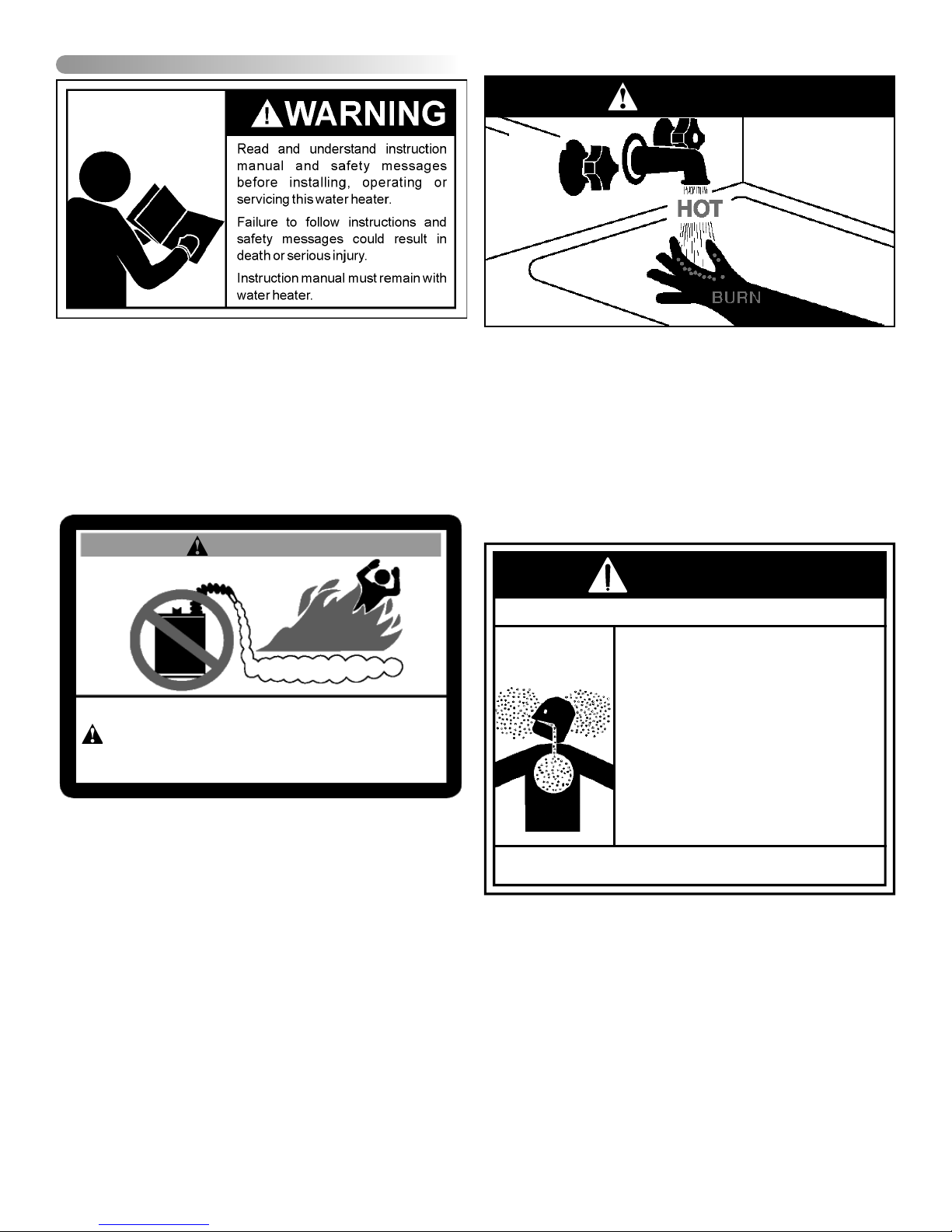
Hot water produced by this appliance can cause severe burns
due to scalding. The hazard is increased for young children,
the aged or the disabled when water temperatures exceed
52°C (125°F). Use tempering valves, also known as mixing
valves, in the hot-water system to reduce the risk of scalding
at point-of-use such as lavatories, sinks and bathing facilities
(see Figures 11 & 12). Such precautions must be followed
when this heater is operated in combination with dishwashing
or space heating applications.
Safety Warning (Flammable Vapours)
Safety Warning (Carbon Monoxide)
WARNING
FLAMMABLES
FIRE AND EXPLOSION HAZARD
Can result in serious injury or death
Do not store or use gasoline or other flammable vapours and liquids
in the vicinity of this or any other appliance. Storage of or use of gasoline
or other flammable vapours or liquids in the vicinity of this or any other
appliance can result in serious injury or death.
There is a risk of property damage, personal injury or death
from the by-products of combustion (e.g., fl ue gases), in
using fuel-burning appliances such as water heaters. Areas
that may not be suitable for water heater installation include
those where fl ammable liquids, gasoline, solvents, adhesives
etc. are stored. Also not suitable are areas where enginedriven equipment is stored, operated or repaired. Flammable
vapour products should not be stored or used near the water
heater or air intake. Due to the nature of air movement,
fl ammable vapours can be carried some distance from the
point of storage. Although the safety system is designed to
reduce the risk of fl ammable vapour related fi res, the gas-
fi red water heater igniter or burner fl ame can ignite these
vapours causing a fl ashback, fi re or explosion, which may
result in severe property damage, serious personal injury or
death. If fl ammable liquids or vapours have spilled or leaked
in the area of the water heater, leave the area immediately
and call the fi re department from a neighbor's home. Do not
attempt to clean the spill until all ignition sources have been
extinguished.
– 4 –
Flammable Vapours
As with all fuel burning equipment, this heater requires an
adequate supply of air for combustion. An insuffi cient air
supply can result in poor combustion or the re-circulation
of the fl ue gases. Such a condition may cause soot build-
up and present a fi re hazard. Flow reversal of fl ue gases
may cause an increase of carbon monoxide inside of the
dwelling that could result in serious bodily harm or death from
asphyxiation.
MAKE SURE THE FLOW OF COMBUSTION AIR IS NOT
RESTRICTED.
WARNING
Breathing Hazard - Carbon Monoxide Gas
• Install vent system in accordance with codes.
• Do not operate water heater if flood damaged.
• For operation above 10,100’ (3,079 m), a high
altitude orifice must be installed.
• Do not operate if soot buildup is present.
• Do not obstruct water heater air intake with
insulating jacket.
• Do not obstruct blower air intake.
• Do not place chemical vapor emitting products
near water heater.
• Gas and carbon monoxide detectors are
available.
• No vent damper installation is compatible with
this power vented water heater.
Breathing carbon monoxide can cause brain damage or death.
Always read and understand instruction manual.
Relief Valve Requirements (T&P)
All water heaters must be fi tted with a proper temperature
and pressure relief valve. These valves must be certifi ed as
meeting the requirements of the "Standard For Relief Valves
For Hot Water Supply Systems, ANSI Z21.22/CSA 4.4".
Flooding/Freezing/Fire Damage
If this water heater has been exposed to fl ooding, freezing,
fi re or any unusual condition, do not put it into operation until
it has been inspected and approved by a qualifi ed service
technician. THESE CONDITIONS CAN RESULT IN UNSEEN
INTERNAL DAMAGE.
CAUTION
Hydrogen gas can be produced in a hot water system
served by this heater that has not been used for a long period of time (generally two (2) weeks or more). Hydrogen
gas is extremely fl ammable and can ignite when ex-
posed to a spark or fl ame. To reduce the risk of injury un-
der these conditions, it is recommended that the hot water
faucet be opened for several minutes at the kitchen sink
before using any electrical appliance connected to the hot
water system. Use caution in opening faucets. If hydrogen
is present, there will probably be an unusual sound such
as air escaping through the pipe as the water begins to
fl ow. There should be no smoking or open fl ame near the
faucet at the time it is open.
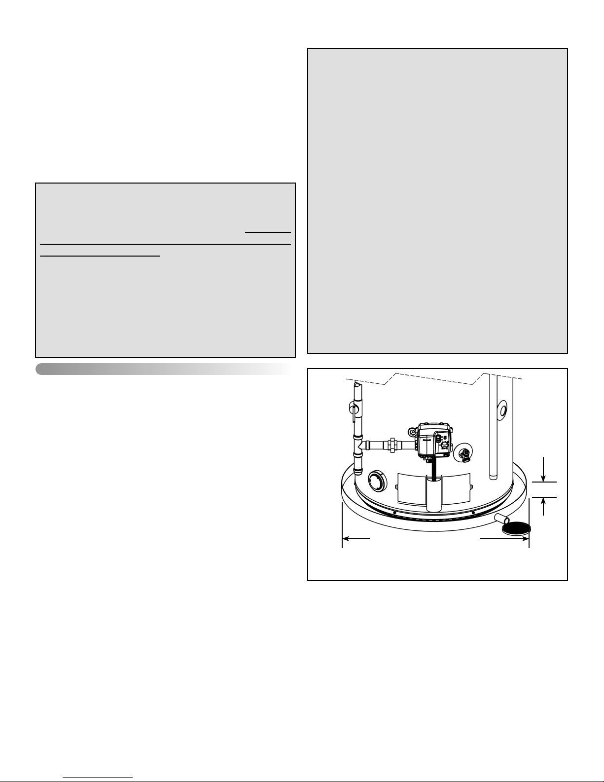
Location Requirements
IMPORTANT:
This water heater must be installed strictly in accordance
with the instructions enclosed, and all applicable electrical,
fuel and building codes. It is possible that connections to
the water heater, or the water heater itself, may develop
leaks. It is therefore strongly recommended that the water heater be installed so that any leakage of the tank or
related water piping is directed to an adequate drain in
such a manner that it cannot damage the building, furniture, fl oor covering, adjacent areas, lower fl oors of the
structure or other property subject to water damage. This
is particularly important if the water heater is installed in a
multi-story building, on fi nished fl ooring or carpeted sur-
faces. THE MANUFACTURER WILL NOT ASSUME ANY
LIABILITY for damage caused by water leaking from the
water heater, pressure relief valve, or related fi ttings. Se-
lect a location as centralized within the piping system as
possible. In any location selected, it is recommended that
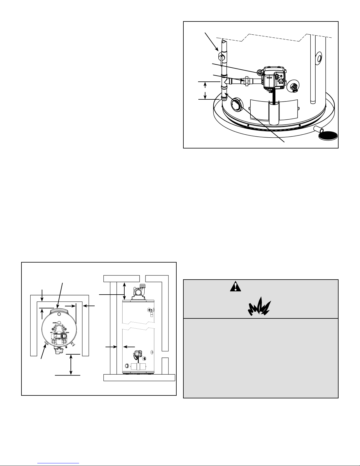
a suitable drain pan be installed under the water heater.
This pan must limit the water level to a MAXIMUM depth of
45mm (1 3/4 in.) and have a diameter that is a minimum of
50mm (2 in.) greater than the diameter of the water heater.
Suitable piping shall connect the drain pan to a properly
operating fl oor drain. When used with a fuel-fi red heater,
this drain pan must not restrict combustion air fl ow.
INSTALLATION
Unpacking the Water Heater
Important: Do not remove any permanent instructions, labels,
or the data label from outside of the water heater or on the
inside of panels.
Remove exterior packaging and place installation com-
•
ponents aside.
Inspect all parts for damage prior to installation and start-
•
up.
Completely read all instructions before attempting to
•
assemble and install this product.
Read the “Safety” section of this manual first and then
•
entire manual carefully. If you don’t follow safety rules,
the water heater will not operate properly. It could
cause DEATH, SERIOUS BODILY INJURY AND/OR
PROPERTY DAMAGE. This manual contains instructions for installation, operation, and maintenance of
the gas-fired water heater. It also contains warnings
throughout the manual that you must read and be aware
of. All warnings and instructions are essential to proper
operation of the water heater and your safety. Since
we cannot put everything on the first few pages, READ
ENTIRE MANUAL BEFORE ATTEMPTING TO INSTALL
OR OPERATE THE WATER HEATER.
After installation, dispose of packaging material in the
•
proper manner.
45mm max
(1 3/4 in.)
AT LEAST 50mm (2 in.) GREATER
THAN THE DIAMETER OF THE
WATER HEATER.
PIPE TO
ADEQUATE
DRAIN
Figure 1
The water heater must be installed indoors in an area not
subject to freezing temperatures and in a vertical position
on a level surface. Water heaters located in unconditioned
spaces (e.g., attics, basements etc.) may require insulation
of the water piping, drain piping and venting to protect against
condensation. The power vented series of water heaters are
designed to vent the products of combustion horizontally
through the wall or vertically through the roof. The blower
expels the products of combustion by means of certifi ed plastic
piping to the outdoors without the need for a conventional
chimney.
– 5 –
Select a location as centralized within the piping system as
possible. The heater should be located in an area where
leakage of the tank or connections will not result in damage to
the area adjacent to the water heater or to lower fl oors of the
structure (see "IMPORTANT" notice on the previous page).
Before installing this water heater, consideration and planning
must be given to the following details:
•
Proximity to walls and other objects (see "Clearance and
Accessibility").
•
Access to gas supply (see "Gas Supply").
•
Routing and support of the vent piping and termination
(see "Venting").
•
Position of water supply and placement of water piping
and floor drain (see "Water Supply").
In Earthquake Zones
The water heater must be braced, anchored, or strapped to
avoid moving during an earthquake. Contact local utilities for
code requirements in your area.
MANUAL GAS
SHUT-OFF
GAS
CONTROL/
THERMOSTAT
GROUND-
JOINT UNION
76mm (3 in.)
DRIP LEG
Figure 3
Closet Installations
The water heater may be installed in a closet with a door that
is connected to a bedroom or bathroom providing the units are
installed and vented per the manufacturer's instructions.
Floor Surfaces
If installing over carpeting, the carpeting must be protected
by a metal or wood panel beneath the water heater. The
protective panel must extend beyond the full width and depth
of the water heater by at least 76mm (3 in.) in each direction
or if in an alcove or closet installation, the entire fl oor must
be covered by the panel.
Clearances and Accessibility
ALCOVES
AIR INTAKE *
BACK
SENSOR *
FRONT 600mm
(24 in.) MIN.
FOR SERVICE
* DO NOT BLOCK AIR INTAKE OR SENSOR ACCESS. ENSURE ADEQUATE
CLEARANCE FOR AIR SUPPLY
TOP TO
CEILING
SIDES
SIDES
CLOSETS
The minimum clearances between the heater and com-
•
bustible materials are:
Top 200mm (8 in.)
Front 100mm (4 in.)
Rear and Sides 0mm (0 in.)
Note: These requirements are also listed on the data plate
located on the front of the water heater.
The water heater is certified for installation on a combus-
•
tible floor.
Figure 2 may be used as a reference guide to locate the
specifi c clearance locations. A minimum of 600mm (24 in.)
of front clearance and 100mm (4 in.) on each side should be
provided for inspection and service.
Gas Supply
DANGER
Explosion Hazard
• Install a gas supply shut-off valve.
• Do not connect a natural gas water heater to
a L.P. gas supply.
• Do not connect a L.P. gas water heater to a
natural gas supply
• Failure to follow these instructions can result
in death, an explosion or carbon monoxide
poisoning.
Figure 2
– 6 –
Read the data plate to be sure the water heater is made
for the type of gas you will be using in your home. This
information will be found on the data plate located above the
gas control valve. If the information does not agree with the
type of gas available, do not install or attempt to start.

Note: An odourant is added by the gas supplier to the gas
used by this water heater. This odourant may fade over an
extended period of time. Do not depend upon this odourant
as an indication of leaking gas.
This gas piping must be installed in accordance with all
provincial requirements and the latest edition of "Natural Gas
and Propane Installation Code" CSA-B149.1.
Use properly sized gas piping and to ensure full gas input
and a properly sized gas supply regulator to ensure adequate
gas supply pressure. The supply piping and regulator must
be large enough to satisfy the requirements of all appliances
connected to the gas service and when all appliances are
operating simultaneously. Undersize piping and insuffi cient
pressure can restrict the gas fl ow causing the water heater
to perform poorly. Improperly sized piping may pose a safety
hazard.
Note: When installing gas piping, apply sealing compounds
approved for use with natural and propane gas.
Install a readily accessible manual shut-off valve in the
1.
gas supply line as required "Natural Gas and Propane
Installation Code" CSA-B149.1. The owner/operator
must be shown the location of this valve and be given
instructions on how to use it to shut off the gas to the
heater.
Install a drip leg (if not already incorporated as part of
2.
the water heater) as shown. The drip leg must be no
less than 76mm (3 in.) long for the accumulation of dirt,
foreign material, and water droplets.
Install a ground joint union, or other approved gas dis-
3.
connect, between the gas control/thermostat and the
manual shut-off valve. This is to allow easy removal of
the gas control/thermostat.
Turn the gas supply on and check for leaks. Use a chlo-
4.
ride-free soap and water solution (bubbles forming indicate a leak) or other approved method.
Gas Supply Pressure
Important: The gas supply pressure must not exceed the
maximum supply pressure as stated on the water heater's
data plate.
Gas Leak Testing
Important: This water heater and its gas connection must be
leak tested before placing the appliance in operation.
•
If the code requires the gas lines to be tested at a pressure exceeding 14 in. w.c. (3.5 kPa), the water heater
and its manual shut-off valve must be disconnected from
the gas supply piping system and the line capped.
•
If the gas lines are to be tested at a pressure less than
14 in. w.c. (3.5 kPa), the water heater must be isolated
from the gas supply piping system by closing its manual
shut-off valve.
WARNING
Exposure to a higher gas supply pressure
may cause damage to the control, resulting
in explosion or fi re. Consult your local gas
supplier and gas authorities. DO NOT PUT
INTO SERVICE IF OVER-PRESSURIZATION
HAS OCCURRED.
Gas Operating Pressures
The gas supply pressure and burner manifold pressure is listed
on the data plate located on the front of the heater above the
gas control/thermostat. Ensure the gas supply pressure to the
water heater and the burner manifold pressure are properly
adjusted while all appliances are in operation. Refer to Figure
35 for Honeywell Gas Control/Thermostat Details.
Rated Manifold
Pressure. in.
w.c. (kPa)
10 (2.48) 9.2 (2.28) 10.2 (2.53)
4 (0.99) 3.6 (0.89) 4.4 (1.09)
U.L. and CSA recognized fuel gas and Carbon Monoxide (CO)
detectors are recommended in all applications and should
be installed using the manufacturer's instructions and local
codes, rules or regulations.
Air Requirements
A gas water heater cannot operate properly without the correct
amount of air for combustion. Do not install in a confi ned area
such as a closet, unless you provide adequate air supply.
Never obstruct the fl ow of dilution/ventilation air. If you have
any doubts or questions at all, call your gas supplier. Failure
to provide the proper amounts of air can result in a fi re or
explosion and cause death, serious bodily injury, or property
damage. The combustion and dilution air inlets are shown in
Figure 5.
Important: Air must not come from a corrosive atmosphere.
Any failure due to corrosive elements in the atmosphere is
excluded from warranty coverage.
Installations in or for certain places including, but not limited
to, those listed below may require outdoor air for combustion
and dilution to reduce the risk of chemical exposure. In these
cases it is probably necessary to install a Power Direct Vent
(PDV) water heater:
Beauty shops, Photo processing labs
•
Buildings with indoor pools
•
Water heaters installed in some laundry, hobby or craft
•
rooms
Water heaters installed near chemical storage areas
•
In some cases, isolation of the water heater from corrosive
environments may be required.
Min. Manifold
Pressure. in.
w.c. (kPa)
Max. Manifold
Pressure. in.
w.c. (kPa)
– 7 –
Appliances In Enclosures
If the water heater is installed in an enclosure ensure an air
supply is provided as required by the current edition of CSAB149.1, the Natural Gas and Propane Installation Code.
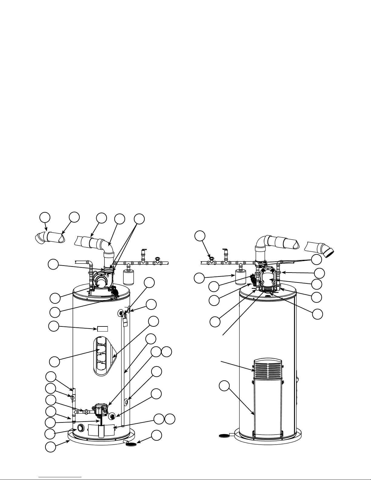
Typical Installation
1. Vent Termination Elbow with
Rodent Screen
2. *Vent Pipe
3. *Vent Pipe Coupling (if required)
4. *Vent Pipe Elbow (long radius)
5. Limit Switch (see Figure 9)
6. T&P Valve
7. Diptube
8. Baffle Assembly
9. * Discharge Pipe
10. Gas Control Valve/Thermostat
(Honeywell)
11. Gas Valve Electronic Control
Module And Cover (Honeywell)
12. Drain Valve
13. Outer Gas Door
14. Manifold Door Assembly (behind
outer door) (see Figures 6 & 7)
15. *Floor Drain
16. *Metal Drain Pan
17. Flammable Vapour Sensor (under
cover) (see Figure 8)
18. **Combo Heating System Return
Inlet (Optional)
19. Air Inlet Snorkel
20. **Combo Heating System Supply
Outlet (Optional)
21. Blower with Power Cord (see
Figure 9)
22. Air Switch (inside box) (see Figure
9)
23. Junction Box (see Figure 9)
24. Junction Box Cover (see Figure 6)
25. Air Tubing (see Figure 9)
26. Rubber Coupling
27. Gear Clamp
28. Flue Collector
29. Hot-Water Outlet Nipple
30. Anode (under cap)
31. Cold-Water Inlet Nipple
32. Flexible Manifold Tube (see
Figures 6 & 7)
33. Viewport (see Figures 6 & 7)
34. Flame Sensor Rod (see Figures 6
& 7)
35. Gas Orifice (see Figures 6 & 7)
36. Sheet Metal Burner (see Figures 6
& 7)
37. Gas Manifold (see Figures 6 & 7)
38. Hot-Surface Igniter (see Figures 6
& 7)
39. Manifold Door Gasket (see Figures
6 & 7)
40. Manifold Door (see Figures 6 & 7)
41. Two Piece Grommet With Clip
(see Figures 6 & 7)
42. *Inlet Water Shut-off Valve
43. *Gas Supply*
44. *Main Manual Gas Shut-off Valve
45. *Ground Joint Union (gas connection)
46. *Sediment Trap/Dirt Leg
47. *Union (water connection)
48. Rating Plate
49. ***Control Harness
50. *Thermal Expansion Tank
(required for all closed systems)
1
2
3
4
27
42
26
21
21
48
6
20
7
9
10
11
8
50
47
21
31
Dilution
Air Inlets
Combustion
Air Inlets
29
47
28
29
30
18
43
44
19
12
45
46
49
17
16
Front View Rear View
Figure 4 Figure 5
– 8 –
15
13
14
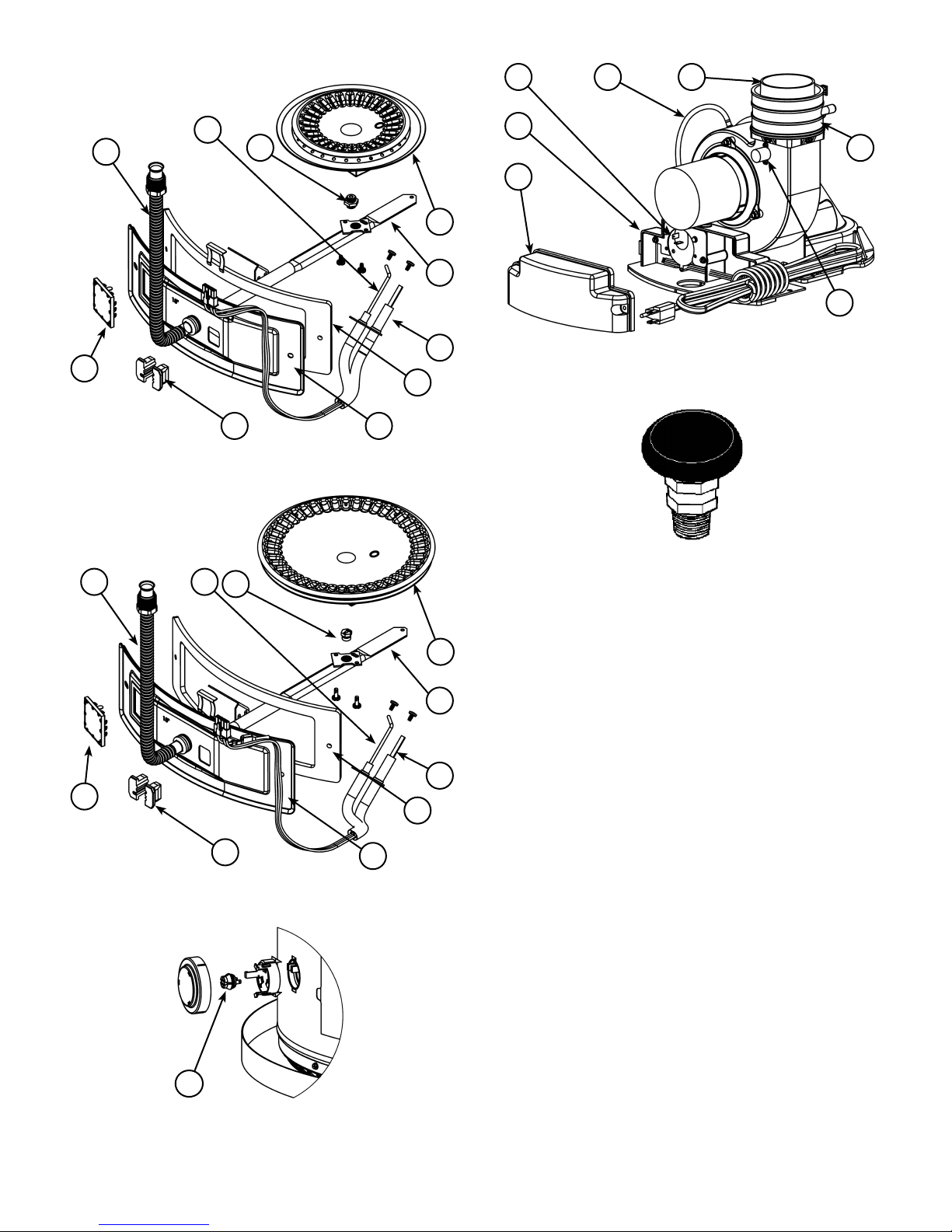
Natural gas and Propane main
burner with igniter assembly for
40k to 50k Btu/hr models
22
25
26
34
32
33
Figure 6
Natural gas and Propane
main burner with igniter
assembly for 60k to 75k
Btu/hr models
32 34
35
35
23
27
24
36
37
5
38
39
4041
Figure 9
Vacuum relief valve
install per local
codes (not supplied
with heater).
Figure 10
33
Figure 7
41
40
39
36
37
38
* Items not supplied with the water heater
** The side recirculation loop connections may not be used
as the primary water inlet and outlet connections. For
your convenience, plugs are installed in these fittings
at the factory. Remove these plugs if needed for your
specific installation. Otherwise (as with all connections)
check for leaks while filling the tank with water and after
completing the installation.
*** Caution: harness has 120 VAC present during opera-
tion.
Replacement Parts And Deliming
Products
Replacement parts and recommended delimer may be
ordered through authorized servicers or distributors. When
ordering parts, provide complete model and serial numbers
(see rating plate), quantity and name of part desired. Standard
hardware items may be purchased locally.
17
Figure 8
– 9 –
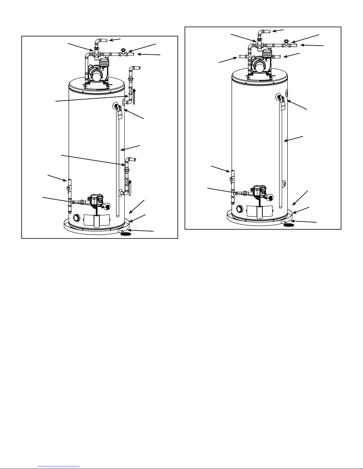
Water Piping - Mixing Valve Usage
MIXING VALVE
SUGGESTED PlPING
ARRANGEMENT FOR
TOP CONNECTIONS
CERTAIN
MODELS ARE
EQUIPPED WITH
SIDE PLUMBING
CONNECTIONS FOR
SPACE HEATING.
THE HOT AND
COLD FITTING
ASSEMBLlES
(PART #9001262)
CAN BE ORDERED
THROUGH AN
AUTHORIZED
DEALER
GAS
SUPPLY
DRAIN
VALV E
* NOTE: THE
T&P VALVE
CAN BE PIPED
DIRECTLY TO
THE DRAIN
TEMPERED
POTABLE WATER
Figure 11
This appliance has been design certifi ed as complying with
CSA Standard for water heaters and certain models with
side plumbing connections are considered suitable for Water
(Potable) Heating and Space Heating.
The water heater should not be subjected to excessive
water pressure fl uctuations and should not be subjected to
an operating pressure greater than 80 psi. If this occurs, a
pressure-reducing valve with a bypass should be installed in
the cold-water inlet line. This should be placed on the supply
to the entire house in order to maintain equal hot and cold
water pressure.
SHUT-OFF
VALV E
COLD-WATER
INLET
TEMERATUREPRESSURE
RELIEF VALVE
DISCHARGE
PIPE (DO NOT
CAP OR PLUG)
TO SUITABLE
DRAIN
150mm (6”)
MAX. AIR
GAP*
METAL
DRAlN
PAN
MIXING VALVE
SUGGESTED PlPING
ARRANGEMENT FOR
TOP CONNECTIONS
NON-TEMPERED
WATER SUPPLY
GAS
SUPPLY
DRAIN
VALV E
* NOTE: THE
T&P VALVE
CAN BE PIPED
DIRECTLY TO
THE DRAIN
TEMPERED
POTABLE WATER
SHUT-OFF
VALV E
COLD-WATER
INLET
NON-TEMPERED
WATER RETURN
TEMERATUREPRESSURE
RELIEF VALVE
DISCHARGE
PIPE (DO NOT
CAP OR PLUG)
TO SUITABLE
DRAIN
150mm (6”)
MAX. AIR
GAP*
METAL
DRAlN
PAN
Figure 12
Mixing Valves
Water heaters are intended to produce hot water. Water
heated to a temperature which satisfi es space heating, clothes
washing, dish washing, and other sanitizing needs can scald
and cause permanent injury upon contact. Short repeated
heating cycles caused by small hot-water uses can cause
temperatures at the point of use to exceed the water heater’s
temperature setting by up to 11C° (20F°).
Some people are more likely to be permanently injured by
hot water than others. These include the elderly, children, the
infi rm and the physically/mentally disabled. Table 3 shows the
approximate time-to-burn relationship for normal adult skin.
National plumbing code requirements limit the temperatures of
certain fi xtures in the home. Local codes may have additional
requirements. In addition to these requirements, if anyone
using hot water in your home fi ts into one of these groups,
then you must take special precautions. In addition to using
the lowest possible temperature setting that satisfi es your
hot water needs, a means such as a Mixing Valve, should
be used at the hot water taps used by these people or at the
water heater. Mixing valves are available at plumbing supply
or hardware stores. Consult a Qualifi ed Installer or Service
Agency. Follow mixing valve manufacturer’s instructions
for installation of the valves (see Figures 11 & 12). Before
changing the factory setting on the thermostat, read the
“Temperature Regulation” section in this manual.
– 10 –
Exhaust Venting
This heater is designed to exhaust the products of combustion
(fl ue gases) to the outdoors using a sealed piping system.
Table 1 lists the allowable vent materials and sizing
information. Figure 16 shows the general venting layout
while Figures 17-19 show various end termination details and
clearances. Connection of the venting piping to the blower is
shown in Figures 21-25.
Correct installation of the venting system is essential to the
safe and effi cient operation of this water heater. Vent piping
must be installed in accordance with all applicable national and
provincial codes. All installations shall meet the requirements
as stated in the latest edition of the "Natural Gas and
Propane Installation Codes" CSA-B149-1.
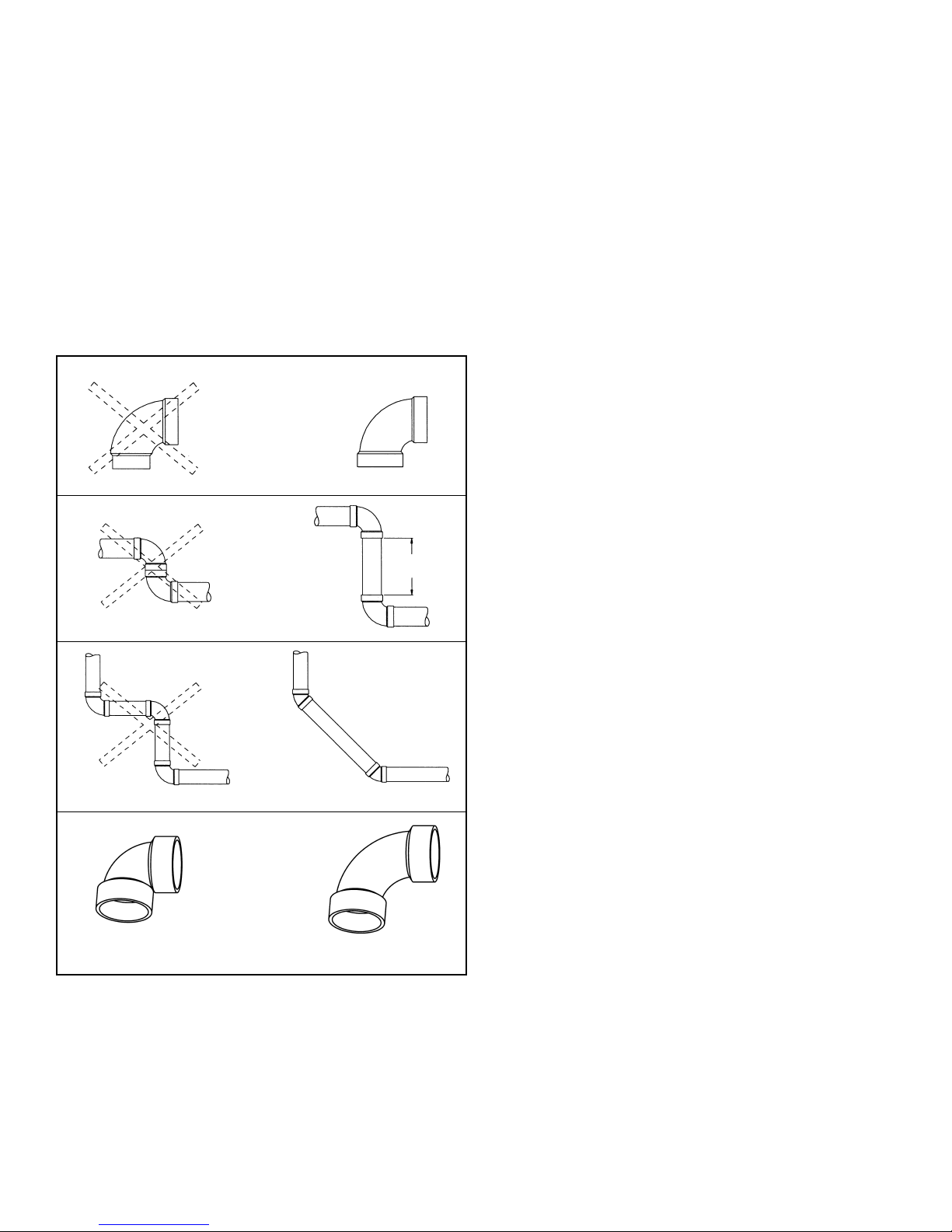
PREFERRED PRACTICESNOT RECOMMENDED
STREET ELBOW NORMAL ELBOW
150mm
(6 in.) min.
BACK TO BACK ELBOWS
PREFERRED PRACTICE
90° SHORT SWEEP ELBOW
(MORE RESTRICTIVE)
Figure 13
Note: The information provided in Figure 13 is intended as a
guideline for good vent installation practices only and is not
intended to restrict venting options beyond those restrictions
established by the latest edition of the "Natural Gas and
Propane Installation Codes" CSA-B149-1 or any applicable
local and provincial codes.
90° LONG SWEEP ELBOW
(LESS RESTRICTIVE)
High Ambient Temperature Installations
This heater requires room air to lower the fl ue gas temperatures
before the gases pass through the vent system. The dilution
air inlets are located on the rear of the blower assembly (see
Figures 5 & 21). As the room temperature rises, the ability
to lower the fl ue gases lessens so special attention to the
choice of venting material is required. Establishing the ambient
temperatures where the heater and the venting is installed is
very important, especially in regions with warmer climates or
any region that experiences hot summers. Ambient conditions
hotter than 43°C (110°F) require that the venting material be
either CPVC or polypropylene. Areas that can experience
high ambient environments include closets, alcoves, areas
under staircases, attics especially in metal roofed buildings,
areas with restricted air movement, rooms with large solar
gains, metal sheds, industrial or commercial enterprises
and venting systems exposed to direct sunlight. For high
temperature environments, obtain high limit switch upgrade
Kit # 9008306015 and use the higher rated vent piping.
Important Notes and Warnings
This heater is certified to be installed using Schedule
•
40 PVC or CPVC or polypropylene plastic vent material.
All jurisdictions require that this material is approved to
ULC S636. Only use approved material. All venting material and components must be joined with the approved
primer/cleaner and solvent cement.
Do not common vent this heater with any other appli-
•
ance.
During operation the plastic piping will expand as it heats
•
up and contract as it cools down. This is normal for this
type of venting. Rigidly fastening the vent piping can
cause undue stress that may result in the cracking or
fracturing the vent piping material. A fracture of the venting pipe may pose a serious safety hazard. To prevent
stressing of the vent system, all hangers and supports
must allow the vent piping freedom to move.
Use long sweep elbows wherever possible. Closely-
•
coupled elbows and short radius elbows can reduce the
venting capacity.
All power vented water heaters generate a certain
•
amount of operational noise. In order to minimize noise
transmission to the support structure, it is recommended
to use isolation pads between the pipe hangers and the
vent pipe.
Most power vent installations develop some condensa-
•
tion in the vent piping. When using long runs of venting
or when the venting passes through cold or unheated
areas, considerable amounts of condensate from the flue
gases can develop. Provision must be made for the condensate to drain freely from the system or to be collected
in a condensate trap(s) that can be drained. Damage or
fracture of the vent piping may occur if the condensate
is allowed to collect and freeze. Pooling of condensate
can restrict airflow and can cause nuisance failures of
the system.
– 11 –
Venting Terminations and Sizing
Refer to Figure 16 and Table 1 for vent pipe materials and
•
sizing. Examples of the vent terminations are shown in
Figures 17 and 18. If the installation requires a vent riser,
suitable drainage must be provided to ensure condensation does not accumulate. Termination through a roof is
shown Figure 19.
40, 50 and 60-gallon heaters with rated inputs of 50k
•
Btu/hr or less are supplied with a 2” termination elbow, a
plastic “rodent screen” and a wire mesh "rodent screen"
(see Figure 14).
50 and 75-gallon heaters with rated inputs of 60k Btu/hr
•
or more are supplied with a 3” termination elbow, a plastic
“rodent screen” and a wire mesh "rodent screen" (see
Figure 15).
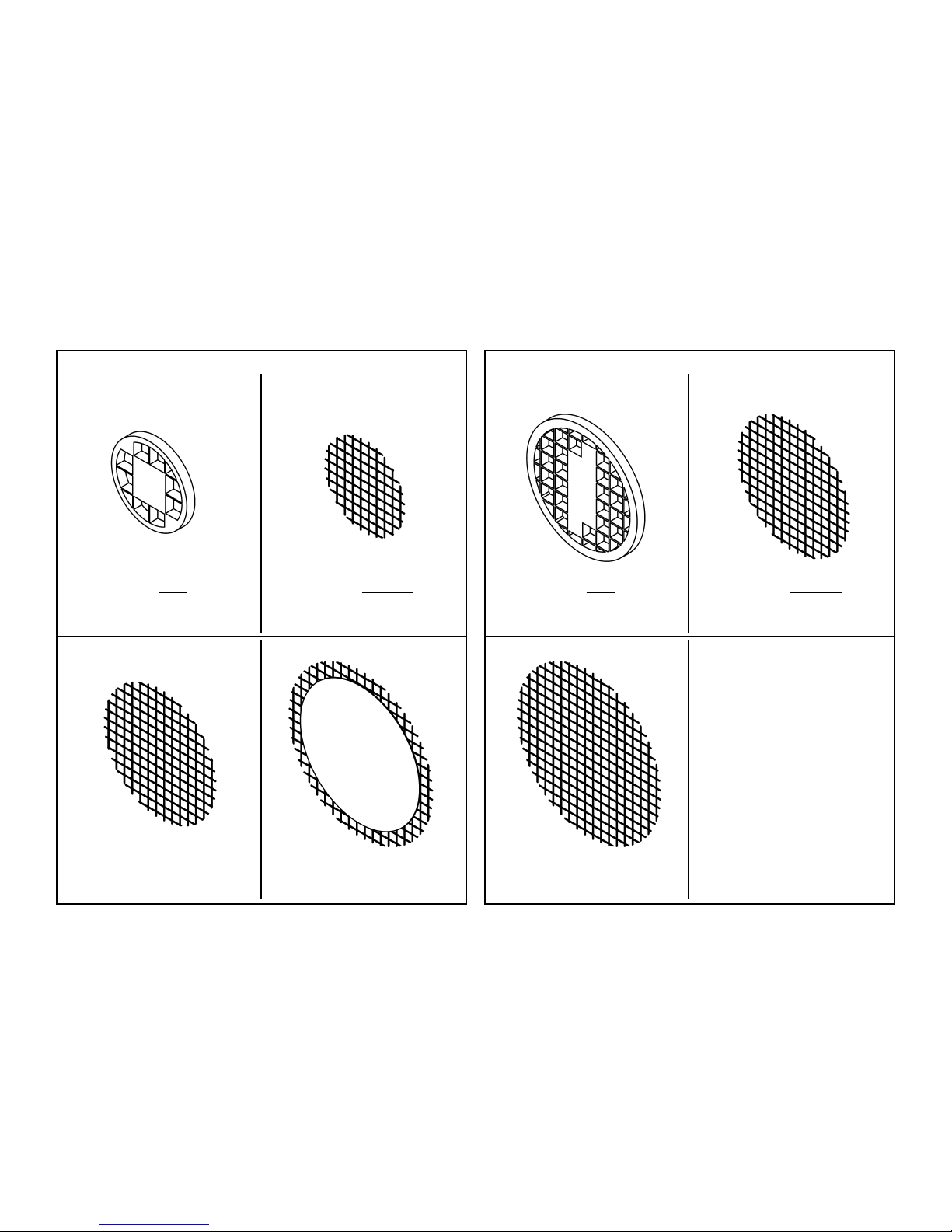
Rodent Screens
A vent termination screen is required to keep foreign objects,
rodents and small birds from entering the venting system.
These screens have been sized to ensure maximum energy
effi ciency of the vent system based on the “equivalent length”
of the vent piping. CHOOSE ONLY the ONE SCREEN THAT
MATCHES YOUR VENTING CONFIGURATION (see Figures
14 & 15). How to determine the “equivalent length” is shown
in Figure 16 and in Table 1. This will allow for easy removal
for inspection and cleaning.
•
For heaters with rated inputs of 50k Btu/hr or less see
Figure 14.
•
For heaters with rated inputs of 60k Btu/hr or more see
Figure 15.
For heaters with rated inputs of 50k Btu/hr or less:
with 2 in. venting (short) with 2 in. venting (long)
VENT LENGTH LESS THAN OR
EQUAL TO 20 EQUIVALENT FT.
(6.1 METRES) USE THIS SCREEN
(SUPPLIED).
VENT LENGTH GREATER THAN
20 EQUIVALENT FT.
(6.1 METRES) USE THIS SCREEN
(SUPPLIED).
with 3 in. venting with 4 in. venting
For heaters with rated inputs of 60k Btu/hr or more:
with 3 in. venting (short) with 3 in. venting (long)
VENT LENGTH LESS THAN OR
EQUAL TO 20 EQUIVALENT FT.
(6.1 METRES) USE THIS SCREEN
(SUPPLIED).
VENT LENGTH GREATER THAN
20 EQUIVALENT FT.
(6.1 METRES) USE THIS SCREEN
(SUPPLIED).
with 4 in. venting
VENT LENGTH GREATER THAN
50 EQUIVALENT FT.
(15.2 METRES) USE THIS SCREEN
(FIELD SUPPLIED).
VENT LENGTH GREATER THAN
125 EQUIVALENT FT.
(38.1 METRES) USE THIS SCREEN
(ORDER KIT # 9008310015).
Figure 14
– 12 –
VENT LENGTH GREATER THAN
125 EQUIVALENT FT.
(38.1 METRES) USE THIS SCREEN
(FIELD SUPPLIED).
Figure 15
 Loading...