

GSW ANSI Z21.10.1 - CSA 4.1, RESIDENTIAL GAS WATER HEATERS Installation And Operating Manual
Installation and Operating Manual
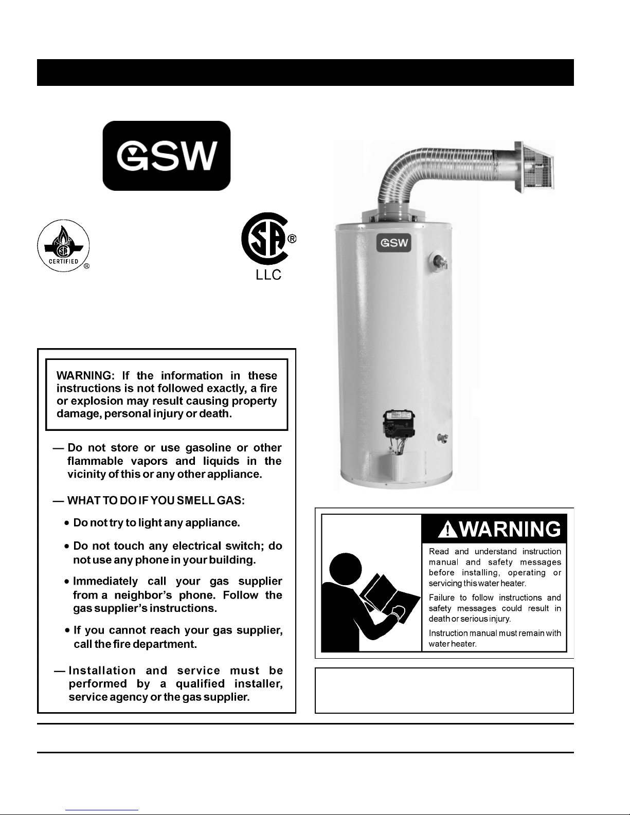
RESIDENTIAL GAS WATER HEATERS
DIRECT VENTED GAS MODELS
NOT FOR USE IN MANUFACTURED (MOBILE) HOMES
www.gsw-wh.com
ALL TECHNICAL AND WARRANTY QUESTIONS: SHOULD BE DIRECTED TO THE LOCAL DEALER FROM WHOM THE WATER HEATER WAS
PURCHASED. IF YOU ARE UNSUCCESSFUL, PLEASE CONTACT THE COMPANY LISTED ON THE RATING PLATE ON THE WATER HEATER.
KEEP THIS MANUAL IN THE POCKET ON HEATER FOR FUTURE REFERENCE
WHENEVER MAINTENANCE ADJUSTMENT OR SERVICE IS REQUIRED.
1404 327539-000
• For Your Safety •
AN ODOURANT IS ADDED TO THE GAS USED
BY THIS WATER HEATER.

TABLE OF CONTENTS
SAFE INSTALLATION, USE AND SERVICE . . . . . . . . . . .3
GENERAL SAFETY . . . . . . . . . . . . . . . . . . . . . . . . . . . . . .4
INTRODUCTION . . . . . . . . . . . . . . . . . . . . . . . . . . . . . . . . 6
Qualifi ed Installer Or Service Agency . . . . . . . . . . . . 6
Preparing For The Installation. . . . . . . . . . . . . . . . . . 6
TYPICAL INSTALLATION. . . . . . . . . . . . . . . . . . . . . . . . . .7
Get To Know Your Water Heater - Gas Models
(List Referencing Figures 1-5). . . . . . . . . . . . . . . . . . 7
Replacement Parts And Deliming Products . . . . . . . 8
Combo Heating Inlet And Outlet Side Taps . . . . . . . . 8
High Limit Controls (Energy Cut Off). . . . . . . . . . . . . 8
Thermostat/Water Temperature
LOCATING THE NEW WATER HEATER. . . . . . . . . . . . . .9
Facts To Consider About The Location . . . . . . . . . . . 9
External/Internal Damage . . . . . . . . . . . . . . . . . . . . . 9
Air Requirements . . . . . . . . . . . . . . . . . . . . . . . . . . 10
Confi ned Space Installations. . . . . . . . . . . . . . . . . . 10
Clearances To Combustibles
Floors With Carpeting
Clearance For Servicing
Chemical Vapour Corrosion . . . . . . . . . . . . . . . . . . 10
Storage Of Flammable Liquids . . . . . . . . . . . . . . . . .11
Insulation Blankets . . . . . . . . . . . . . . . . . . . . . . . . . .11
Water Piping . . . . . . . . . . . . . . . . . . . . . . . . . . . . . . 12
Water Pressure
Mixing Valves
INSTALLING THE NEW WATER HEATER . . . . . . . . . . . 13
Water Piping Installation . . . . . . . . . . . . . . . . . . . . . 13
Closed Water Systems . . . . . . . . . . . . . . . . . . . . . . 13
Thermal Expansion . . . . . . . . . . . . . . . . . . . . . . . . . 13
Temperature-Pressure Relief Valve. . . . . . . . . . . . . 14
T&P Valve Discharge Pipe Requirements:
Temperature-Pressure Relief Valve And
Pipe Insulation
Filling The Water Heater . . . . . . . . . . . . . . . . . . . . . 15
Space Heating And Potable Water Systems . . . . . . 16
Combo Heating . . . . . . . . . . . . . . . . . . . . . . . . . . . . 17
System Requirements
Installation
Gas Piping. . . . . . . . . . . . . . . . . . . . . . . . . . . . . . . . 18
Sediment Trap. . . . . . . . . . . . . . . . . . . . . . . . . . . . . 19
High Altitude Installations . . . . . . . . . . . . . . . . . . . . 19
Venting . . . . . . . . . . . . . . . . . . . . . . . . . . . . . . . . . . 20
Vent Terminal Clearances . . . . . . . . . . . . . . . . . . . . 20
DV Termination Safety Cover . . . . . . . . . . . . . . . . . 21
Vent Connections . . . . . . . . . . . . . . . . . . . . . . . . . . 21
Locating Clearance Hole For Vent . . . . . . . . . . . . . 21
Standard Vent Arrangement . . . . . . . . . . . . . . . . . . 21
Vent Assembly. . . . . . . . . . . . . . . . . . . . . . . . . . . . . 22
Securing Vent Termination Assembly To
The Exterior Wall. . . . . . . . . . . . . . . . . . . . . . . . . . . 22
Vent Restricter Plate . . . . . . . . . . . . . . . . . . . . . . . . 22
Uncompressing The Corrugated Tubing . . . . . . . . . 22
Vent Connection To The Water Heater . . . . . . . . . . 23
Offset Vent Arrangement. . . . . . . . . . . . . . . . . . . . . 23
Installation Checklist . . . . . . . . . . . . . . . . . . . . . . . . 25
LIGHTING INSTRUCTIONS. . . . . . . . . . . . . . . . . . . . . . .26
TEMPERATURE REGULATION . . . . . . . . . . . . . . . . . . .27
Temperature Regulation . . . . . . . . . . . . . . . . . . . . . 27
Temperature Adjustment
Operating The Temperature Control System. . . . . . 27
Water Temperature Adjustment
Operating Modes And Settings
FOR YOUR INFORMATION. . . . . . . . . . . . . . . . . . . . . . . 28
External Damage . . . . . . . . . . . . . . . . . . . . . . . . . . 28
Start Up Conditions . . . . . . . . . . . . . . . . . . . . . . . . . 28
Condensate
Smoke/Odour
Thermal Expansion . . . . . . . . . . . . . . . . . . . . . . . . . 28
Strange Sounds . . . . . . . . . . . . . . . . . . . . . . . . . . . 29
Operational Conditions . . . . . . . . . . . . . . . . . . . . . . 29
Smelly Water
“Air” In Hot Water Faucets
High Water Temperature Shut Off System
MAINTENANCE . . . . . . . . . . . . . . . . . . . . . . . . . . . . . . . .30
Housekeeping . . . . . . . . . . . . . . . . . . . . . . . . . . . . . 30
Flood Damage. . . . . . . . . . . . . . . . . . . . . . . . . . . . . 30
Venting System Inspection . . . . . . . . . . . . . . . . . . . 30
Pilot And Main Burner . . . . . . . . . . . . . . . . . . . . . . . 30
Burner Flames. . . . . . . . . . . . . . . . . . . . . . . . . . . . . 31
Servicing The Water Heater . . . . . . . . . . . . . . . . . . 31
Removing And Replacing The Gas Control Valve/
Thermostat . . . . . . . . . . . . . . . . . . . . . . . . . . . . . . . 31
Removing The Gas Control Valve/Thermostat:
Replacing The Gas Control Valve/Thermostat:
Removing The Manifold/Burner Assembly . . . . . . . 31
Removing The Burner From The Manifold/Burner
Assembly. . . . . . . . . . . . . . . . . . . . . . . . . . . . . . . . . 32
Natural Gas (Low Nox) & Propane (LP) Gas Burner
Replacing The Pilot/Thermopile Assembly . . . . . . . 32
Replacing The Manifold/Burner Assembly . . . . . . . 33
Piezoelectric Igniter System . . . . . . . . . . . . . . . . . . 34
Testing The Igniter System . . . . . . . . . . . . . . . . . . . 34
Temperature-Pressure Relief Valve Test . . . . . . . . . 34
Draining, Refi lling And Flushing . . . . . . . . . . . . . . . 34
To Drain The Water Heater Storage Tank
To Refi ll The Water Heater Storage Tank
To Flush The Water Heater Storage Tank
Drain Valve Washer Replacement . . . . . . . . . . . . . 35
Anode Rod Maintenance. . . . . . . . . . . . . . . . . . . . . 35
To Remove The Anode Rod:
To Install The Anode Rod:
LEAKAGE CHECKPOINTS . . . . . . . . . . . . . . . . . . . . . . .37
Service . . . . . . . . . . . . . . . . . . . . . . . . . . . . . . . . . . 37
REFERENCE PARTS LISTING . . . . . . . . . . . . . . . . . . . .38
TROUBLESHOOTING GUIDELINES. . . . . . . . . . . . . . . .40
NOTES . . . . . . . . . . . . . . . . . . . . . . . . . . . . . . . . . . . . . . .44
2 www. gsw-wh .com
SAFE INSTALLATION, USE AND SERVICE
Your safety and the safety of others is extremely important in the installation, use and servicing of this water heater.
Many safety-related messages and instructions have been provided in this manual and on your own water heater to warn you
and others of a potential injury hazard. Read and obey all safety messages and instructions throughout this manual. It is very
important that the meaning of each safety message is understood by you and others who install, use or service this water heater.
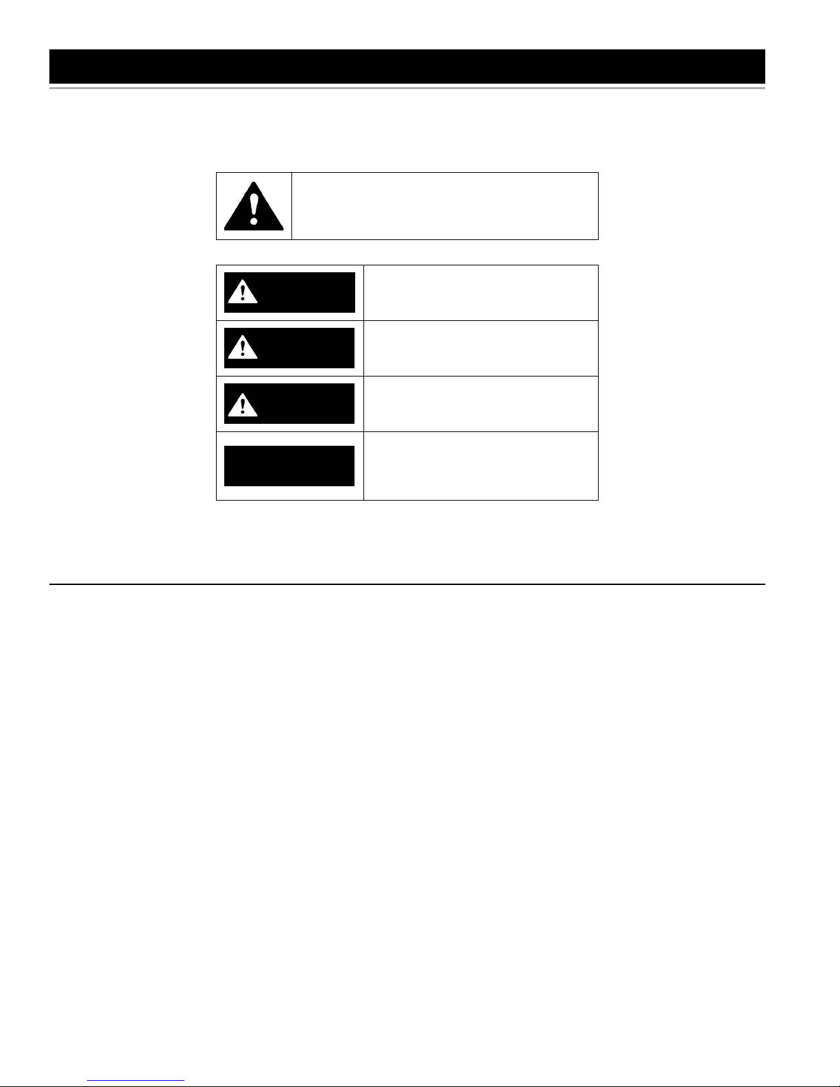
This is the safety alert symbol. It is used to alert you
to potential personal injury hazards. Obey all safety
messages that follow this symbol to avoid possible
injury or death.
DANGER indicates an imminently
DANGER
WARNING
CAUTION
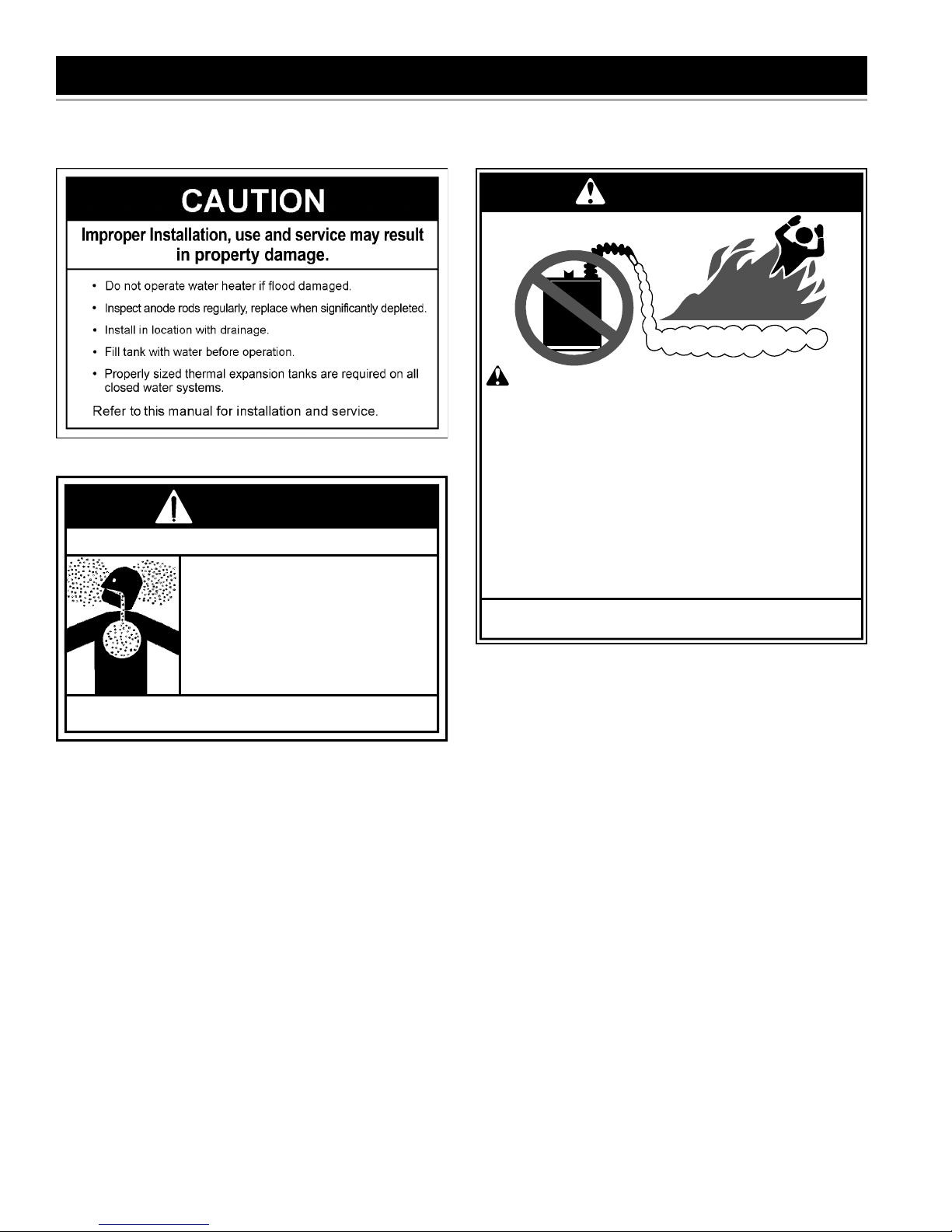
CAUTION
hazardous situation which, if not avoided,
will result in death or injury.
WARNING indicates a potentially
hazardous situation which, if not avoided,
could result in death or injury.
CAUTION indicates a potentially
hazardous situation which, if not avoided,
could result in minor or moderate injury.
CAUTION used without the safety alert
symbol indicates a potentially hazardous
situation which, if not avoided, could
result in property damage
All safety messages will generally tell you about the type of hazard, what can happen if you do not follow the safety message
and how to avoid the risk of injury.
IMPORTANT DEFINITIONS
Qualifi ed Installer: A qualifi ed installer must have ability equivalent to a licensed tradesman in the fi elds of plumbing,
air supply, venting and gas supply, including a thorough understanding of the requirements of the National Fuel Gas
Code as it relates to the installation of gas fi red water heaters. The qualifi ed installer must also be familiar with the
design features and use of fl ammable vapor ignition resistant water heaters and have a thorough understanding of this
Installation and Operating manual.
Service Agency: A service agency also must have ability equivalent to a licensed tradesman in the fi elds of plumbing, air
supply, venting and gas supply, including a thorough understanding of the requirements of the National Fuel Gas Code
as it relates to the installation of gas fi red water heaters. The service agency must also have a thorough understanding
of this Installation and Operating manual, and be able to perform repairs strictly in accordance with the service guidelines
provided by the manufacturer.
Gas Supplier: The Natural Gas or Propane Utility or service who supplies gas for utilization by the gas burning appliances
within this application. The gas supplier typically has responsibility for the inspection and code approval of gas piping
up to and including the Natural Gas meter or Propane storage tank of a building. Many gas suppliers also offer service
and inspection of appliances within the building.
www. gsw-wh .com 3
GENERAL SAFETY
• Do not store or use gasoline or other flammable
• Avoid all ignition sources if you smell gas.
• Do not expose water heater control to excessive
• Use only gas shown on rating plate.
• Maintain required clearances to combustibles.
• Keep ignition sources away from faucets after
4 www. gsw-wh .com
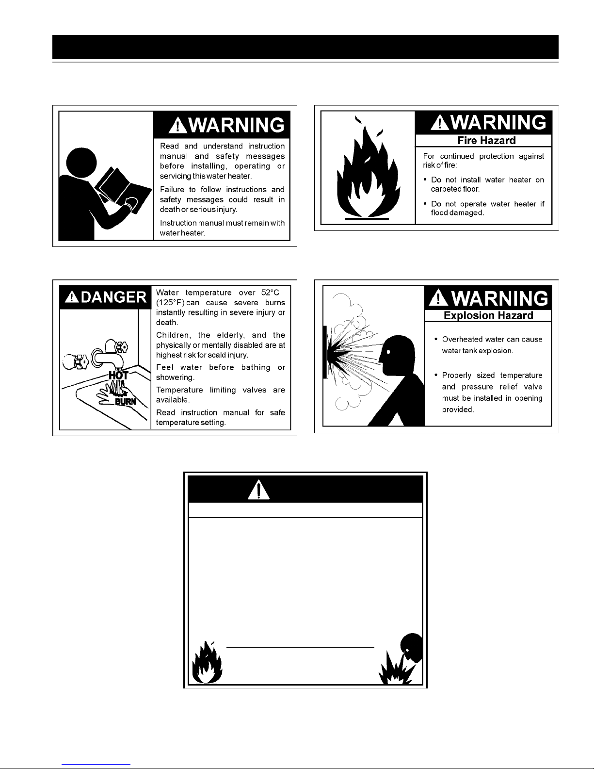
WARNING
Fire or Explosion Hazard
vapours and liquids in the vicinity of this water
heater, the vent termination hood or any other
appliance.
gas pressure.
extended period of non-use.
Read instruction manual before
installing, using or servicing
water heater.
GENERAL SAFETY
DANGER
WARNING
Breathing Hazard - Carbon Monoxide Gas
• Install vent system in accordance with codes.
• Do not operate water heater if flood damaged.
• For operation above 2347m (7,700’), a high
altitude orifice must be installed.
• Do not operate if soot buildup is present.
• Do not place chemical vapor emitting products
near water heater or vent termination hood.
• Gas and carbon monoxide detectors are
available.
Breathing carbon monoxide can cause brain damage or death.
Always read and understand instruction manual.
FLAMMBLE
Vapours from flammable
liquids may explode and
catch fire causing death or
severe burns.
Do not use or store
flammable products such as
gasoline, solvents or adhesives in the same room or
area near the water heater or
the vent termination hood.
Keep flammable products:
1. far away from heater,
2. in approved containers,
3. tightly closed and
4. out of children's reach.
Installation: Do not install the water heater or the vent termination hood where flammable products will be stored or used.
Flammable Vapours
Water heater has a main
burner and pilot. While
operating, the pilot flame:
1. is in continuous operation
and
2. will ignite flammable
vapours.
Vapours:
1. cannot be seen,
2. are heavier than air,
3. go a long way on the floor
and
4. can be carried from other
rooms by air currents.
www. gsw-wh .com 5

INTRODUCTION
Thank You for purchasing this water heater. Properly
installed and maintained, it should give you years of trouble
free service.
This water heater is suitable for potable water heating
and space heating applications but not for space heating
only applications.
Abbreviations found in this Installation and Operating
manual:
• CSA - Canadian Standards Association
• ANSI - American National Standards Institute
• ASME - American Society of Mechanical Engineers
This gas-fi red water heater is design certifi ed by CSA
International, under Water Heater Standard ANSI
Z21.10.1 • CSA 4.1 (current edition).
QUALIFIED INSTALLER OR SERVICE AGENCY
Installation and service of this water heater requires ability
equivalent to that of a Qualifi ed Agency (as defi ned by
ANSI below) in the fi eld involved. Installation skills such
as plumbing, air supply, venting, gas supply and electrical
supply are required in addition to electrical testing skills
when performing service.
ANSI Z223.1 2006 Sec. 3.3.83: “Qualifi ed Agency” - “Any
individual, fi rm, corporation or company that either in
person or through a representative is engaged in and is
responsible for (a) the installation, testing or replacement
of gas piping or (b) the connection, installation, testing,
repair or servicing of appliances and equipment; that
is experienced in such work; that is familiar with all
precautions required and that has complied with all the
requirements of the authority having jurisdiction.”
If you are not qualifi ed (as defi ned by ANSI above) and
licensed or certified as required by authority having
jurisdiction to perform a given task, do not attempt to
perform any of the procedures described in this manual.
If you do not understand the instructions given in this
manual do not attempt to perform any procedures outlined
in this manual.
PREPARING FOR THE INSTALLATION
1. Read the “General Safety” section of this manual
fi rst and then entire manual carefully. If you don’t
follow safety rules, the water heater will not operate
properly. It could cause DEATH, SERIOUS BODILY
INJURY AND/OR PROPERTY DAMAGE. This manual
contains instructions for installation, operation,
and maintenance of the gas-fi red water heater. It
also contains warnings throughout the manual that
you must read and be aware of. All warnings and
instructions are essential to proper operation of the
water heater and your safety. Since we cannot put
everything on the fi rst few pages, READ ENTIRE
MANUAL BEFORE ATTEMPTING TO INSTALL OR
OPERATE THE WATER HEATER.
2. The installation must conform with these instructions
and local code authority having jurisdiction. In
absence of local codes, installation must comply with
current editions of the “Natural Gas and Propane
Installation Code” B149.1 and “Canadian Electrical
Code (C22.1), Part I” . All documents are available
from:
Canadian Standards Association,
5060 Spectrum Way,
Mississauga, Ontario, Canada
L4W 5N6
3. If after reading this manual you have any questions or
do not understand any portion of the instructions, call
the local gas utility or the manufacturer whose name
appears on the rating plate.
4. Carefully plan the place where you are going to put
the water heater. Correct combustion, vent action, and
vent pipe installation are very important in preventing
death from possible carbon monoxide poisoning and
fi res (see Figure 6). Examine the location to ensure
the water heater complies with the “Locating The New
Water Heater” section in this manual.
5. For installation in areas subject to earthquakes, this
water heater must be braced, anchored, or strapped to
avoid falling or moving during an earthquake. Contact
local utilities for code requirements in your area.
6. This product is certifi ed to comply with a maximum
weighted average of 0.25% lead content as required
in some areas.
6 www. gsw-wh .com
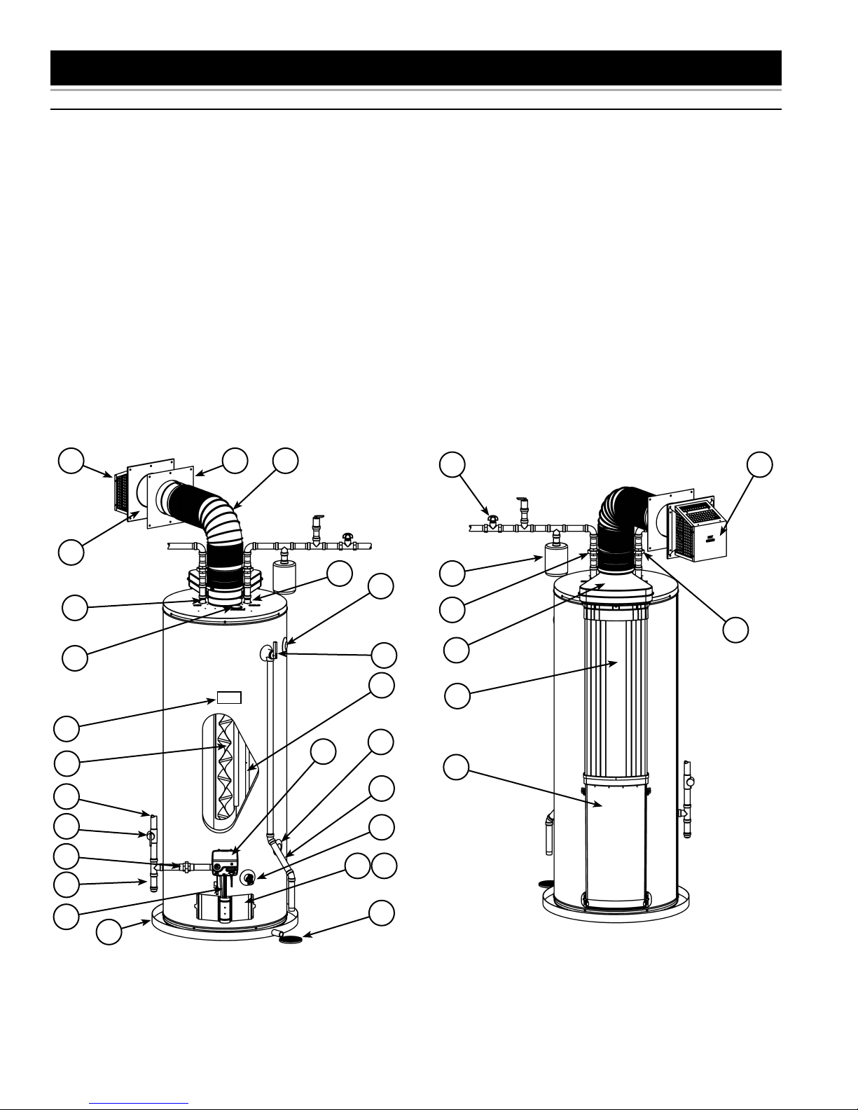
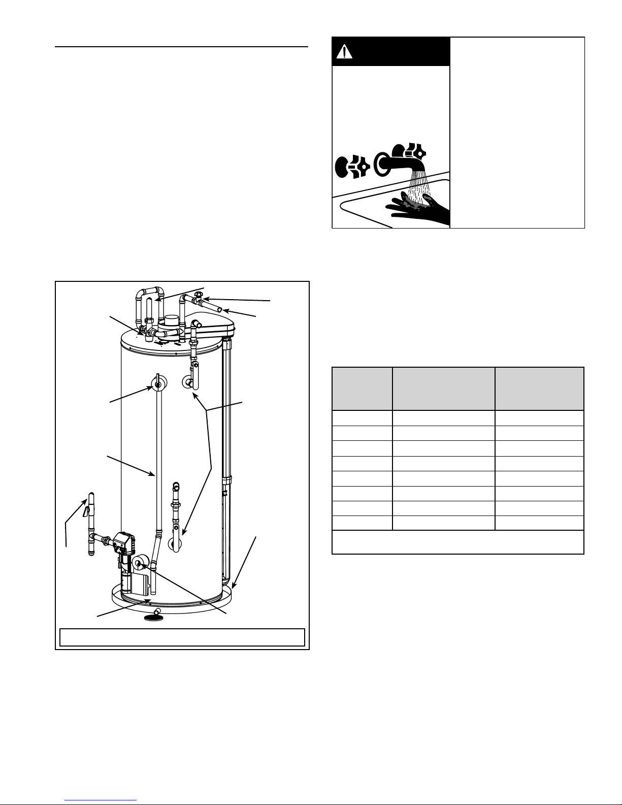
GET TO KNOW YOUR WATER HEATER - GAS MODELS (LIST REFERENCING FIGURES 1-5)
1 Vent Termination Hood
2 Wall Plate
3 ***Vent Pipe
4 Cold Water Inlet Nipple/Diptube
5 **Combo Heating System Supply
Outlet (Optional)
6 T&P Valve
7 Gas Control Valve/Thermostat
(Honeywell)
8 **Combo Heating System Return
Inlet (Optional)
9 *Discharge Pipe
10 Drain Valve
11 Outer Gas Door
12 Manifold Door Assembly (behind
outer door) (see Figure 3 &
Figure 4)
13 *Floor Drain
14 *Metal Drain Pan
15 Flexible Manifold Tube (see
Figure 3 & Figure 4)
TYPICAL INSTALLATION
16 *Sediment Trap
17 *Ground Joint Union (gas
connection)
18 *Main Manual Gas Shut-off Valve
19 *Gas Supply
20 Baffl e Assembly
21 Rating Plate
22 Anode (under cap)
23 Hot Water Outlet Nipple (or
Optional Nipple/Anode)
24 *Inlet Water Shut-off Valve
25 *Union (water connection)
26 Air Inlet Snorkel
27 Air Tower
28 ***Airbox
29 *Thermal Expansion Tank (required
for all closed systems)
30 Sheet Metal Burner (see Figure 3 &
Figure 4)
31 Gas Orifi ce (see Figure 3 &
Figure 4)
32 Gas Manifold (see Figure 3 &
33 Manifold Door Gasket (see Figure 3
34 Manifold Door (see Figure 3 &
35 Two Piece Grommet With Clip (see
36 Viewport (see Figure 3 & Figure 4)
37 Flexible Manifold Tube (see
38 Pilot (see Figure 3 & Figure 4)
39 Thermopile (see Figure 3 &
40 Pilot Shield (see Figure 3 &
*, **, *** see notes on following page
Figure 4)
& Figure 4)
Figure 4)
Figure 3 & Figure 4)
Figure 3 & Figure 4)
Figure 4)
Figure 4)
1 32
2
23
22
21
20
19
18
17
16
7
4
11 12
5
6
4
8
9
10
24
29
25
28
27
26
1
25
15
14
Front View
Figure 1
www. gsw-wh .com 7
13
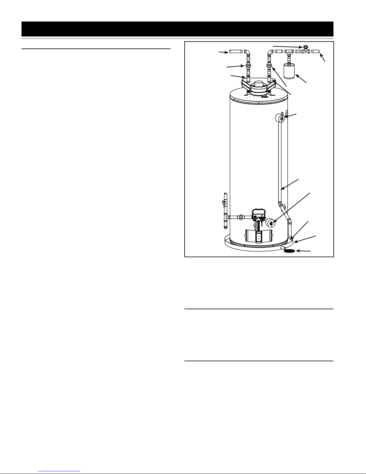
Rear View
Figure 2

37
36
39
38
30
40
Vacuum relief valve
install per local
codes (not supplied
with heater).
31
Figure 5
35
Natural gas and Propane (LP)
main burner with igniter assembly
for 38k to 42k Btu/hr models
Figure 3
Natural gas and Propane
(LP) main burner with igniter
assembly for 47k Btu/hr
models
4039
38
37
36
35
34
32
33
30
31
32
33
34
Notes:
* Items not supplied with the water heater.
** The side recirculation loop connections may not be
used as the primary water inlet and outlet connections.
See “Combo Heating Inlet And Outlet Side Taps”
below.
*** During operation the vent pipe and airbox can get hot.
REPLACEMENT PARTS AND DELIMING PRODUCTS
Replacement parts and recommended delimer may be
ordered through authorized servicers or distributors. When
ordering parts, provide complete model and serial numbers
(see rating plate), quantity and name of part desired.
Standard hardware items may be purchased locally.
COMBO HEATING INLET AND OUTLET SIDE TAPS
Models equipped with Combo Heating capabilities are
shipped with the two side plumbing taps OPEN (items 5
and 8 in Figure 1 and see also Figure 8). If the heater is to
be operated without using the side taps, these openings
must be closed with the two pipe plugs supplied with
the heaters.
HIGH LIMIT CONTROLS (ENERGY CUT OFF)
Thermostat/Water Temperature
This feature is a part of the gas control valve/thermostat
(see Figure 1, item 7) and limits the maximum water
temperature. In the event of the water overheating, this
safety feature shuts off the fuel supply to the burner.
Figure 4
8 www. gsw-wh .com
LOCATING THE NEW WATER HEATER
FACTS TO CONSIDER ABOUT THE LOCATION
Carefully choose an indoor location for the new water
heater because the placement is a very important
consideration for the safety of the occupants in the building
and for the most economical use of the appliance. This
water heater is not for use in manufactured (mobile) homes
or outdoor installation.
Whether replacing an old water heater or putting the water
heater in a new location, the following critical points must
be observed:
1. Select a location indoors as close as practical to the
vent termination position. Figure 27 shows the venting
distances that the heater can be from the outside wall.
Ensure the vent termination position maintains the
clearances as outlined in Figure 27 thru Figure 29.
2. Selected location must provide adequate clearances
for servicing and proper operation of the water heater.
3. Avoid locations that could cause the water heater to
freeze from outside air.
4. Avoid locations that expose the water heater to direct
sunlight.
5. Keep combustibles such as boxes, magazines,
clothes, etc., away from the water heater area.
CAUTION
• Water supply shut-off devices that activate based on
the water pressure differential between the cold water
and hot water pipes connected to the water heater.
• Devices that will turn off the gas supply to a gas water
heater while at the same time shutting off its water
supply.
EXTERNAL/INTERNAL DAMAGE
Do not operate the water heater until it has been fully
checked out by a qualifi ed technician, if the water heater:
• Has been exposed to fi re or damage.
• Displays evidence of sooting.
• Produces steam or unusually hot water.
If the water heater has been fl ooded it must be replaced.
Property Damage Hazard
• All water heaters eventually leak.
• Do not install without adequate drainage.
Installation of the water heater must be accomplished
in such a manner that if the tank or any connections
should leak, the fl ow of water will not cause damage to
the structure. For this reason it is not advisable to install
the water heater in an attic or upper fl oor. In all cases, a
metal drain pan should be installed under the water heater.
Metal drain pans are available at your local hardware store.
Such a metal drain pan must have a clearance of at least
25mm (1”) greater than any point on the water heater’s
outer jacket and must be piped to an adequate drain. The
pan must have a maximum depth of 45mm (1.75”).
Water heater life depends upon water quality, water
pressure and the environment in which the water heater
is installed. Water heaters are sometimes installed in
locations where leakage may result in property damage,
even with the use of a metal drain pan piped to a drain.
However, unanticipated damage can be reduced or
prevented by a leak detector or water shut-off device used
in conjunction with a piped metal drain pan. These devices
are available from some plumbing supply wholesalers and
retailers, and detect and react to leakage in various ways:
• Sensors mounted in the metal drain pan that trigger an
alarm or turn off the incoming water to the water heater
when leakage is detected.
• Sensors mounted in the metal drain pan that turn off
the water supply to the entire building when water is
detected in the metal drain pan.
www. gsw-wh .com 9
AIR REQUIREMENTS
For safe operation an adequate supply of fresh,
uncontaminated air must be provided for combustion.
This gas-fi red water heater is a direct vent model. It
connects directly to the outside of the building through
the vent termination hood. The hood operates as both
the combustion air intake and the heater exhaust port
(see Figure 15).
All combustion air is obtained from outside the building
through this hood. Ensure the area around the termination
hood is always kept clear and that the air supply is not
exposed to contamination or fl ammable vapours.
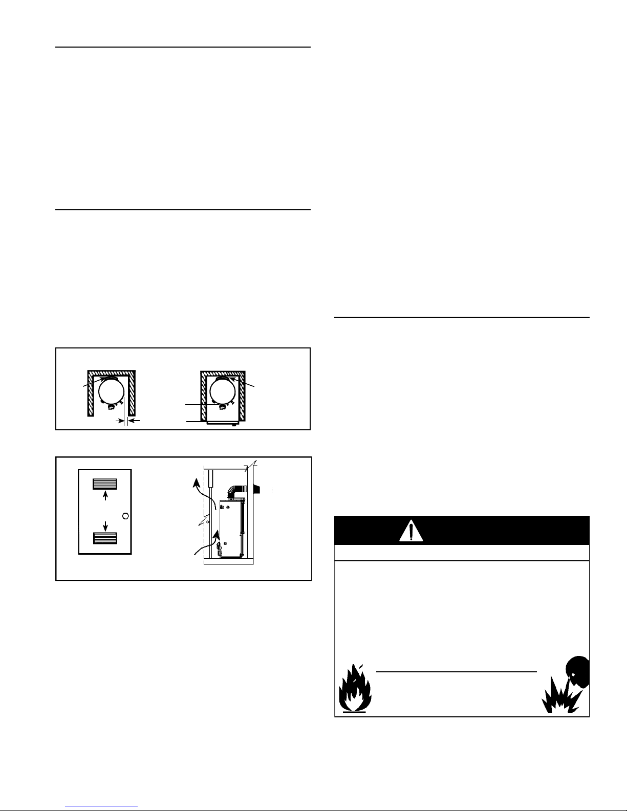
CONFINED SPACE INSTALLATIONS
This water heater connects to the vent termination hood
using the sealed air intake and exhaust piping (see Figure
1 and Figure 2).
During operation this piping can become hot, especially in
areas experiencing high ambient temperatures.
When installed in a confi ned space such as a closet, it is
recommended that the confi ned space be ventilated to
minimize the buildup of heat around the heater. Figure 6
and Figure 7 show an examples of ventilating a confi ned
space.
0mm
(0”) MIN.
TOP VIEW
OF CLOSET
WITHOUT DOOR
0mm
(0”) MIN.
(5.5”) MIN.
140mm
TOP VIEW OF
CLOSET WITH
DOOR
0mm
(0”) MIN.
Figure 6
ROOM AIR
FLOW
VENTILATION
AIR
OPENING
Floors With Carpeting
This water heater must not be installed directly on
carpeting. Carpeting must be protected by a metal or wood
panel beneath the appliance extending beyond the full
width and depth of the appliance by at least 76mm (3”) in
every direction, or if the appliance is installed in an alcove
or closet, the entire fl oor must be covered by the panel.
Failure to heed this warning may result in a fi re hazard.
Clearance For Servicing
Adequate clearance of 610mm (24”) for servicing this
appliance should be considered before installation, such
as changing the anodes, etc.
A minimum clearance of 140mm (5.5”) must be allowed
for access to replaceable parts such as thermostats, drain
valve and relief valve.
When installing the heater, consideration must be given to
proper location. Location selected should be as close to
the wall as practicable and as centralized with the water
piping system as possible.
CHEMICAL VAPOUR CORROSION
CORROSION OF THE FLUEWAYS AND VENT SYSTEM
MAY OCCUR IF AIR FOR COMBUSTION CONTAINS
CERTAIN CHEMICAL VAPOURS. SUCH CORROSION
MAY RESULT IN FAILURE AND RISK OF ASPHYXIATION.
Spray can propellants, cleaning solvents, refrigerator and
air conditioning refrigerants, swimming pool chemicals,
calcium and sodium chloride (water softener salt), waxes,
and process chemicals are typical compounds which are
potentially corrosive. Do not store products of this sort
near the heater or the vent termination hood. Air which is
brought in contact with the heater or the vent termination
hood should not contain any of the chemicals. The Limited
Warranty is voided when failure of water heater is due
to a corrosive atmosphere. See “Limited Warranty” for
complete terms and conditions.
ROOM AIR
FRONT VIEW
OF DOOR
FLOW
Figure 7
Clearances To Combustibles
Minimum clearances between water heater and
combustibles are 0mm (0”) at the sides and rear, 140mm
(5.5”) from the front and 305mm (12”) from top. Minimum
clearances from vent piping to combustibles is 25mm
(1”) except as noted in Figure 20. If clearances stated
on the heater differ from these clearances, install water
heater according to clearances stated on the heater (see
Figure 6).
10 www. gsw-wh .com
WARNING
Fire or Explosion Hazard
• Do not store or use gasoline or other flammable vapours
and liquids in the vicinity of this water heater, the vent
termination hood, or any other appliance.
• Avoid all ignition sources if you smell gas.
• Do not expose water heater control to excessive gas
pressure.
• Use only gas shown on rating plate.
• Maintain required clearances to combustibles.
• Keep ignition sources away from faucets after extended
period of non-use.
Read instruction manual before
installing, using or servicing
water heater.
WARNING
FLAMMABLES
FIRE AND EXPLOSION HAZARD
Can result in serious injury or death
Do not store or use gasoline or other flammable vapors and
liquids in the vicinity of this or any other appliance. Storage or
use of gasoline or other flammable vapors or liquids in the
vicinity of this or any other appliance can result in serious injury
or death.
Flammable Vapors
WARNING
Fire Hazard
For continued protection against
risk of fire:
• Do not install water heater on
carpeted floor.
• Do not operate water heater if
flood damaged.
The water heater must be located and/or protected so it
is not subject to physical damage by a moving vehicle.
Propellants of aerosol sprays and volatile compounds,
(cleaners, chlorine based chemicals, refrigerants, etc.) in
addition to being highly fl ammable in many cases, will also
react to form corrosive hydrochloric acid when exposed to
the combustion products of the water heater. The results
can be hazardous, and also cause product failure.
INSULATION BLANKETS
Insulation blankets are available to the general public for
external use on gas water heaters but are not necessary
with these products. The purpose of an insulation blanket is
to reduce standby heat loss encountered with storage tank
heaters. Your water heater meets or exceeds the current
standards with respect to insulation and standby loss
requirements, making an insulation blanket unnecessary.
Do not install any insulation blankets on this water heater.
WARNING
Breathing Hazard - Carbon Monoxide Gas
• Install water heater in accordance with the
instruction manual and B149.1.
• To avoid injury, combustion air must be taken
from outdoors.
• Do not place chemical vapor emitting products
near water heater or near the vent termination
hood.
• Do not obstruct the vent termination hood.
Breathing carbon monoxide can cause brain damage or death.
Always read and understand instruction manual.
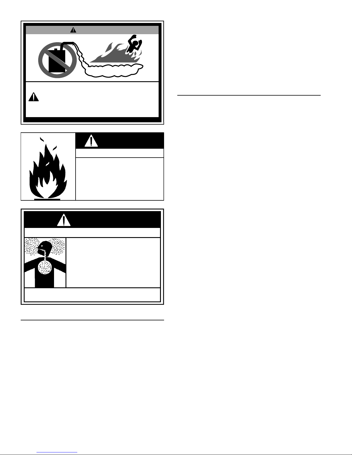
STORAGE OF FLAMMABLE LIQUIDS
Flammable liquids (such as gasoline, solvents, propane
(LP or butane, etc.) and other substances (such as
adhesives, paints, etc.) emit fl ammable vapours which can
be ignited by a gas water heater’s pilot or main burner. The
resulting fl ashback and fi re can cause death or serious
burns to anyone in the area.
Even though this water heater is a fl ammable vapours
ignition resistant (FVIR) water heater and is designed to
reduce the chances of fl ammable vapours being ignited,
gasoline and other fl ammable substances should never
be stored or used in the same vicinity or area containing a
gas water heater, the vent termination hood, or other open
fl ame or spark producing appliance. Examples of such
locations are garages, storage and utility areas.
www. gsw-wh .com 11
WATER PIPING
Water Pressure
The water supply pressure should not exceed 80 psi. If this
occurs, a pressure reducing valve with a bypass should be
installed in the cold water inlet line. This should be placed
on the supply to the entire house in order to maintain equal
hot and cold water pressures. See also “Closed Water
Systems” and “Thermal Expansion” sections.
Mixing Valves
HOT WATER CAN SCALD:
Water heaters are intended to heat water. Water heated
to a temperature which will satisfy space heating, clothes
washing, dish washing, cleaning and other sanitizing
needs can scald and permanently injure you upon contact.
Short repeated heating cycles caused by small hot water
uses can cause a temperature increase of the hot water by
11C° (20F°) higher than the heater’s temperature settings.
SUGGESTED PIPING
ARRANGEMENT FOR
TOP CONNECTIONS
MIXING VALVE
TEMPERED
POTABLE WATER
SHUT-OFF
VALV E
COLD WATER
INLET
Water temperature over
DANGER
52°C (125°F) can cause
severe burns instantly
resulting in severe injury or
death.
Children, the elderly and the
disabled and are at highest
risk of scald injury.
Feel water before bathing or
showering.
HOT
HOT
Temperature limiting devices
such as mixing must be
installed when required by
BURN
codes and to ensure safe
temperatures at fixtures.
Some people are more likely to be permanently injured
by hot water than others. These include the elderly,
children, the infi rm and the physically/mentally disabled.
Table 1 (published by U.S. Government Memorandum,
1978) shows the approximate time-to-burn relationship
for normal adult skin. If anyone using hot water provided
by the water heater being installed fi ts into one of these
groups or if there is a local code or state law requiring a
certain water temperature at the point of use, then special
precautions must be taken (see Figure 8).
TEMPERATUREPRESSURE
RELIEF VALVE
DISCHARGE
PIPE (DO NOT
CAP OR PLUG)
GAS
SUPPLY
305mm
( 12”)
MAX. AIR
GAP*
Figure 8
CERTAIN
MODELS ARE
EQUIPPED WITH
SIDE PLUMBING
CONNECTIONS
FOR SPACE
HEATING. THE HOT
AND COLD FITTING
ASSEMBLIES
(PART #9001262)
CAN BE ORDERED
THROUGH THE
MANUFACTURER
METAL DRAIN
PAN
DRAIN
VALV E
Water
Temperature
°C (°F)
Time for 1st
Degree Burns
(Less Severe Burns)
Time for Permanent
Burns 2nd & 3rd
Degree (Most
Severe Burns)
44 (110) (normal shower temp.)
47 (116) (pain threshold)
47 (116) 35 minutes 45 minutes
50 (122) 1 minute 5 minutes
55 (131) 5 seconds 25 seconds
60 (140) 2 seconds 5 seconds
65 (149) 1 second 2 seconds
68 (154) instantaneous 1 seconds
(U.S. Government Memorandum, C.P.S.C., Peter L. Armstrong,
Sept. 15,1978)
Table 1
In addition to using lowest possible temperature setting
that satisfi es demand of application, a mixing valve should
be installed at the water heater (see Figure 8) or at hot
water taps to further reduce system water temperature.
Mixing valves are available at plumbing supply stores.
Consult a Qualifi ed Installer or Service Agency. Follow
mixing valve manufacturer’s instructions for installation
of the valves. Before changing the factory setting on the
thermostat, read the “Operating The Temperature Control
System” section in this manual.
12 www. gsw-wh .com
INSTALLING THE NEW WATER HEATER
WATER PIPING INSTALLATION
Note: Water piping and vent piping occupy the space
above the water heater. Plan the water piping to ensure
it does not cause interference with the vent piping (see
“Venting”).
• The system should be installed only with piping that is
suitable for potable (drinkable) water such as copper,
CPVC, or polybutylene. This water heater must not be
installed using iron piping or PVC water piping.
• Use only pumps, valves, or fi ttings that are compatible
with potable water.
• It is recommend that only full fl ow ball or gate valves
are used in water piping installations. The use of valves
that may cause excessive restriction to water fl ow is
not recommended.
• Use only 95/5 tin-antimony or other equivalent solder.
Any lead based solder must not be used.
• Piping that has been treated with chromates, boiler
seal, or other chemicals must not be used.
• Chemicals that may contaminate the potable water
supply must not be added to the piping system.
Piping, fi ttings, and valves should be installed according
to the installation drawing (see Figure 9). If the indoor
installation area is subject to freezing temperatures, the
water piping must be protected by insulation.
Important: Heat must not be applied to the water fi ttings on
the heater as they may contain nonmetallic parts. If solder
connections are used, solder the pipe to the adapter before
attaching the adapter to the hot and cold water fi ttings.
Important: Always use a good grade of joint compound
and be certain that all fi ttings are drawn up tight.
1. Install the water piping and fi ttings as shown in Figure
9. Connect the cold water supply (3/4” NPT) to the cold
water inlet fi tting. Connect the hot water supply (3/4”
NPT) to the hot water outlet fi tting.
Important: These models may contain energy saving heat
traps to minimize the migration of heat to the pipes. Do
not remove the inserts within the heat traps.
2. The installation of unions in both the hot and cold water
supply lines is recommended for ease of removing the
water heater for service or replacement.
3. If installing the water heater in a closed water system,
install an expansion tank in the cold water line as
specifi ed under “Closed Water Systems” and “Thermal
Expansion”.
4. Install a shut-off valve in the cold water inlet line. It
should be located close to the water heater and be
easily accessible. Know the location of this valve and
how to shut off the water to the heater.
5. After piping has been properly connected to the water
heater, remove the aerator at the nearest hot water
faucet. Open the hot water faucet and allow the tank
to completely fi ll with water. To purge the lines of
any excess air, keep the hot water faucet open for
3 minutes after a constant fl ow of water is obtained.
Close the faucet, reinstall the aerator and check all
connections for leaks. Repair as needed.
HOT WATER
OUTLET
UNION
3/4” SWEAT
FITTING
SOME
COMPONENTS
NOT SHOWN
FOR CLARITY.
SHUT-OFF
VALV E
UNION
EXPANSION
3/4” SWEAT
FITTING
TEMPERATUREPRESSURE
RELIEF VALVE
DISCHARGE PIPE
(DO NOT CAP
OR PLUG)
DRAIN
VALV E
305mm ( 12”)
MAX.
AIR GAP
FLOOR
DRAIN
COLD
WATER
INLET
TANK
METAL
DRAIN
PAN
Figure 9
Figure 9 shows typical attachment of water piping to the
water heater. The water heater is equipped with 3/4” NPT
water connections.
CLOSED WATER SYSTEMS
Water supply systems may, because of code requirements
or such conditions as high line pressure, among others,
have installed devices such as pressure-reducing valves,
check valves, and back fl ow preventers. Devices such
as these cause the water system to be a closed system.
THERMAL EXPANSION
As water is heated, it expands (thermal expansion). In a
closed system, the volume of water will increase when
heated. As the volume of water increases, there will be a
corresponding increase in water pressure due to thermal
expansion. Thermal expansion can cause premature tank
failure (leakage). This type of failure is not covered under
the limited warranty. Thermal expansion can also cause
intermittent temperature-pressure relief valve operation:
water discharged from the valve due to excessive pressure
build up. The temperature-pressure relief valve is not
intended for the constant relief of thermal expansion. This
condition is not covered under the limited warranty.
www. gsw-wh .com 13
A properly-sized and charged thermal expansion tank must
be installed on all closed systems to control the harmful
effects of thermal expansion. Contact a plumbing service
agency or your retail supplier regarding the installation of
a thermal expansion tank.
Note: To protect against untimely corrosion of hot and cold
water fi ttings, it is recommended that di-electric unions or
couplings be installed on this water heater when connected
to copper pipe.
CAUTION
designated opening nor plugged. The T&P valve must
be installed directly into the fi tting of the water heater
designed for the relief valve. Install discharge piping so
that any discharge will exit the pipe within 305mm ( 12”)
above an adequate fl oor drain, or external to the building.
In cold climates it is recommended that it be terminated at
an adequate drain inside the building. Be certain that no
contact is made with any live electrical part.
The discharge opening must not be blocked or reduced
in size under any circumstances. Excessive length (over
9.14m [30’]), or use of more than four elbows can cause
restriction and reduce the discharge capacity of the valve.
Property Damage Hazard
• Avoid water heater damage.
• Install thermal expansion tank if necessary.
• Do not apply heat to cold-water inlet or hot-water outlet.
• Contact qualified installer or service agency.
TEMPERATURE-PRESSURE RELIEF VALVE
WARNING
Explosion Hazard
• Temperature-pressure relief
valve must comply with ANSI
Z21.22-CSA4.4 and ASME
code.
• Properly sized temperature-
pressure relief valve must be
installed in opening provided.
• Do not plug, block, or cap the
discharge line.
• Failure to follow this warning
can result in excessive tank
pressure, serious injury or
death.
This water heater is provided with a properly rated/sized
and certifi ed combination Temperature-Pressure Relief
Valve (T&P valve) by the manufacturer. The valve is
certifi ed by a nationally recognized testing laboratory
that maintains periodic inspection of production of listed
equipment of materials as meeting the requirements for
Relief Valves for Hot Water Supply Systems, ANSI
Z21.22-CSA 4.4, and the code requirements of ASME.
No valve or other obstruction is to be placed between
the T&P valve and the tank. Do not connect discharge
piping directly to the drain unless a maximum of 305mm
( 12”) air gap is provided. To prevent bodily injury, hazard
to life, or property damage, the relief valve must be
allowed to discharge water in adequate quantities should
circumstances demand. If the discharge pipe is not
connected to a drain or other suitable means, the water
fl ow may cause property damage.
CAUTION
Water Damage Hazard
• Temperature-pressure relief valve discharge pipe
must terminate at an adequate drain.
T&P Valve Discharge Pipe Requirements:
• Shall not be smaller in size than the outlet pipe size
of the valve, or have any reducing couplings or other
restrictions.
• Shall not be plugged or blocked.
• Shall not be exposed to freezing temperatures.
• Shall be of material listed for hot water distribution.
• Shall be installed so as to allow complete drainage
of both the temperature-pressure relief valve and the
discharge pipe.
• Must terminate a maximum of 305mm ( 12”) above a
fl oor drain or external to the building. In cold climates, it
is recommended that the discharge pipe be terminated
at an adequate drain inside the building
• Shall not have any valve or other obstruction between
the relief valve and the drain.
If replaced, the new T&P valve must meet the requirements
of local codes, but not less than a combination temperaturepressure relief valve rated/sized and certifi ed as indicated
in the above paragraph. The new valve must be marked
with a maximum set pressure not to exceed the marked
hydrostatic working pressure of the water heater (150 psi)
and a discharge capacity not less than the water heater
Btu/hr input rate as shown on the water heater’s model
rating plate.
For safe operation of the water heater, the temperaturepressure relief valve must not be removed from its
14 www. gsw-wh .com
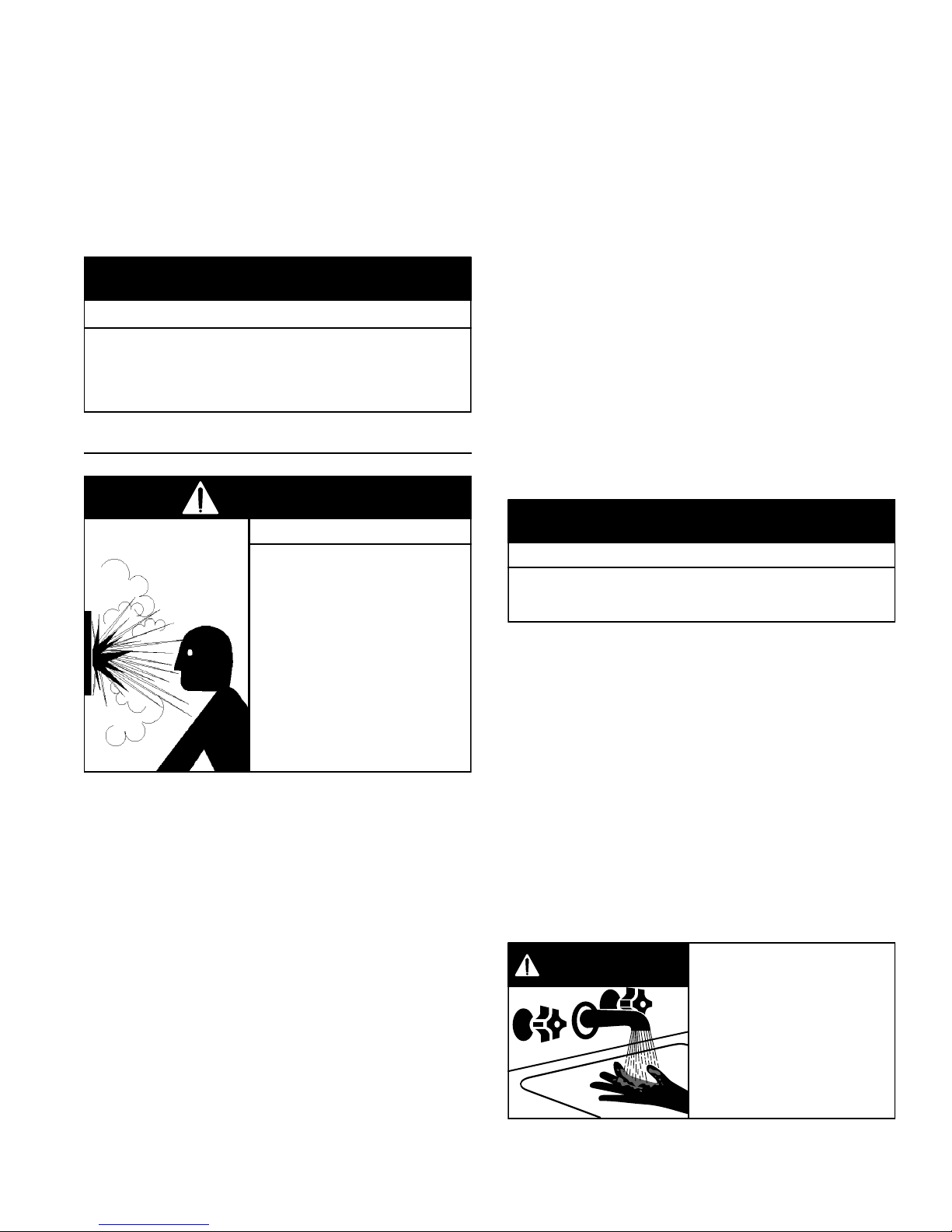
DANGER
HOT
HOT
BURN
• Burn hazard.
• Hot water discharge.
• Keep clear of
temperature-pressure
relief valve discharge.
The T&P valve must be manually operated at least once
a year. Caution should be taken to ensure
1. no one is in front of or around the outlet of the
discharge line, and
2. the water manually discharged will not cause any
bodily injury or property damage because the water
may be extremely hot.
If after manually operating the valve, it fails to completely
reset and continues to release water, immediately close
the cold water inlet to the water heater, follow the draining
instructions in this manual, and replace the temperaturepressure relief valve with a properly rated/sized new one.
Note: The purpose of a temperature-pressure relief valve
is to prevent excessive temperatures and pressures in
the storage tank. The T&P valve is not intended for the
constant relief of thermal expansion. A properly sized
thermal expansion tank must be installed on all closed
systems to control thermal expansion, see “Closed Water
Systems” and “Thermal Expansion” sections.
Temperature-Pressure Relief Valve And Pipe
Insulation
The T&P valve installed on this water heater is covered by
insulation to minimize heat loss. The insulation has a hole
on the bottom side to accommodate the valve outlet and
allow for the piping connection. Do not restrict the outlet
opening of the T&P valve.
1. Locate the hot water (outlet) and cold water (inlet)
pipes to the water heater.
2. Locate the slit running the length of a section of pipe
insulation.
3. Spread the slit open and slip the insulation over the
cold water (inlet) pipe. Apply gentle pressure along
the length of the insulation to ensure that it is fully
seated around the pipe. Also, ensure that the base
of the insulation is fl ush with the water heater. Once
seated, secure the insulation with duct tape, electrical
tape, or equivalent.
4. Repeat steps 2 and 3 for the hot water (outlet) pipe.
5. Add additional sections of pipe insulation as needed.
FILLING THE WATER HEATER
CAUTION
Property Damage Hazard
• Avoid water heater damage.
• Fill tank with water before operating.
• Never use this water heater unless it is completely full
of water. To prevent damage to the tank, the tank must
be fi lled with water. Water must fl ow from the hot water
faucet before turning “ON” gas to the water heater.
T&P Relief Valve Insulation
(Outlet opening on underside)
Manual Relief Lever
T&P Relief Valve
T&P Relief Valve
Drain Line
Figure 10
Locate the temperature and pressure relief valve on the
water heater (also known as a T&P relief valve) (see
Figure 10).
1. Locate the slit running the length of the T&P relief
valve insulation.
2. Spread the slit open and fi t the insulation over the T&P
relief valve (see Figure 10). Apply gentle pressure to
the insulation to ensure that it is fully seated on the
T&P Relief Valve. Once seated, secure the insulation
with duct tape, electrical tape, or equivalent.
Important: The insulation and tape must not block the
discharge opening or hinder access to the manual relief
lever (Figure 10). Ensure a discharge pipe is installed into
the T&P valve discharge opening per the instructions in
this manual.
To fi ll the water heater with water:
1. Close the water heater drain valve by turning handle
to the right (clockwise). The drain valve is on the lower
front of water heater (see Figure 9).
2. Important: If the heater is equipped with plumbing
side taps and they are not connected to piping, ensure
the side taps have been closed with pipe plugs.
3. Open all hot water faucets served by the water heater
to allow air to escape from the tank and the water
piping. Ensure any shut-off valves between the heater
and the faucets are in the open position.
4. Open the cold water supply valve to the water heater.
Notes:
• The cold water supply valve must be left open when
the water heater is in use.
• Avoid water leakage when fi lling the tank. Do not
allow the insulation of the water heater to get wet as
water can reduce the effectiveness of the insulation.
5. Allow water to run until a constant fl ow is obtained.
This will let air out of the water heater and the piping.
6. Check all water piping and connections for leaks.
Repair as needed.
www. gsw-wh .com 15
SPACE HEATING AND POTABLE WATER SYSTEMS
This appliance has been design certifi ed as complying
with American National Standard/CSA Standard for water
heaters and are considered suitable for Water (Potable)
Heating and Space Heating. Note: This water heater
may be used in combination potable water/space heating
system. Do not use in a space heating only application.
WARNING
Toxic Chemical Hazard
• Do not connect to non-potable water system.
Note: Ensure the water heater has been properly sized
to accommodate the needs of the hot water demand and
space heating load. Undersizing the water heater can
result in insuffi cient hot water, excessive condensation
and ineffi cient operation.
• This water heater should not be connected to any
heating systems or components previously used with
a non-potable water heating appliance.
• All piping components connected to this unit for space
heating applications should be suitable for use with
potable water.
• Pumps, valves, piping and fi ttings must be compatible
with potable water.
• Toxic chemicals, such as those used for boiler treatment
shall not be introduced into the potable water used for
space heating.
• When the system requires water for space heating at
temperatures higher than required for domestic water
purposes, a mixing valve must be installed. Please refer
to Figure 8 for suggested piping arrangement.
• Be sure to follow the manual(s) shipped with the air
handler or other type heating system.
• This water heater is not to be used as a replacement
for an existing boiler installation.
• Do not use with piping that has been treated with
chromates, boiler seal or other chemicals and do not
add any chemicals to the water heater piping.
• A properly installed fl ow control valve is required to
prevent thermosiphoning. Thermosiphoning is the
result of a continuous fl ow of water through the air
handler circuit during the off cycle. Weeping (blow off)
of the temperature-pressure relief valve (T&P) or higher
than normal water temperatures are the fi rst signs of
thermosiphoning.
• The hot water line from the water heater should be
vertical past any mixing valve or supply line to the
heating system to remove air bubbles from the system.
16 www. gsw-wh .com
COMBO HEATING
This section serves as a guide for the installation and use
of “Combo” heating systems utilizing a domestic water
heater that has been specifi cally approved for such use.
It is written for those knowledgeable in the required trades
and professionals involved in the design and installation
of Combo Heating Systems.
It is the responsibility of the installer/designer to follow all
applicable codes to ensure the effectiveness and safety
of the installation.
System Requirements
The following requirements must be met for the installation
of Combo Heating Systems:
1. All components used for the distribution of water in
the heating loop must be suitable for potable water.
These include all piping, fi ttings, solder and fl uxes,
pumps for circulation of water, valves, etc.
2. The water heater must not be connected to a hydronic
heating system that has been used previously.
3. No boiler treatment chemicals of any kind shall be
introduced into the system.
4. The Combo System components must be selected
and sized to meet and maintain the total calculated
demands for both domestic service hot water
and space heating requirement. The sizing and
installation must be performed in accordance with
good engineering practice such as “ASHRAE
Handbooks”, HRAI’s Unifi ed Combo Guidelines,
“Hydronics Institute Manuals”, ANSI Z223.1, CSA
F280, National/Provincial Building Codes, ANSI
and/or codes having jurisdiction.
5. The air handler (fan coil) and/or the circulating pump
in a baseboard hydronic loop will require a dedicated
120V circuit. This must be provided and identifi ed for
this purpose.
6. All piping between the water heater and the air handler
or hydronic baseboard loop must be adequately
insulated to reduce heat loss.
7. If the local jurisdiction requires a back-fl ow preventer
in the cold water line, an expansion tank of adequate
size must be installed.
8. “Combo” Heating Systems require higher water
temperatures than other applications. When the
system is used to supply water for Combo Heating
applications, a means, such as mixing valve, must be
installed to temper the water in order to reduce scald
hazard potential (see Figure 11 & Figure 12).
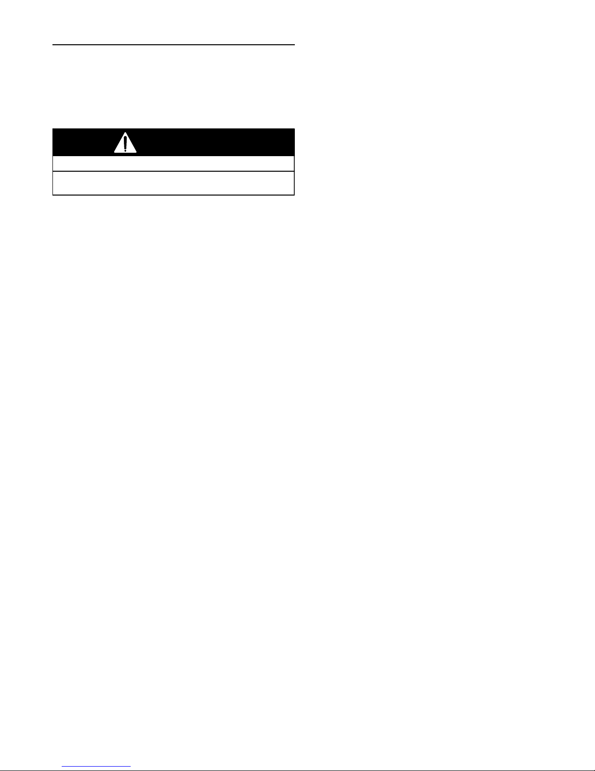
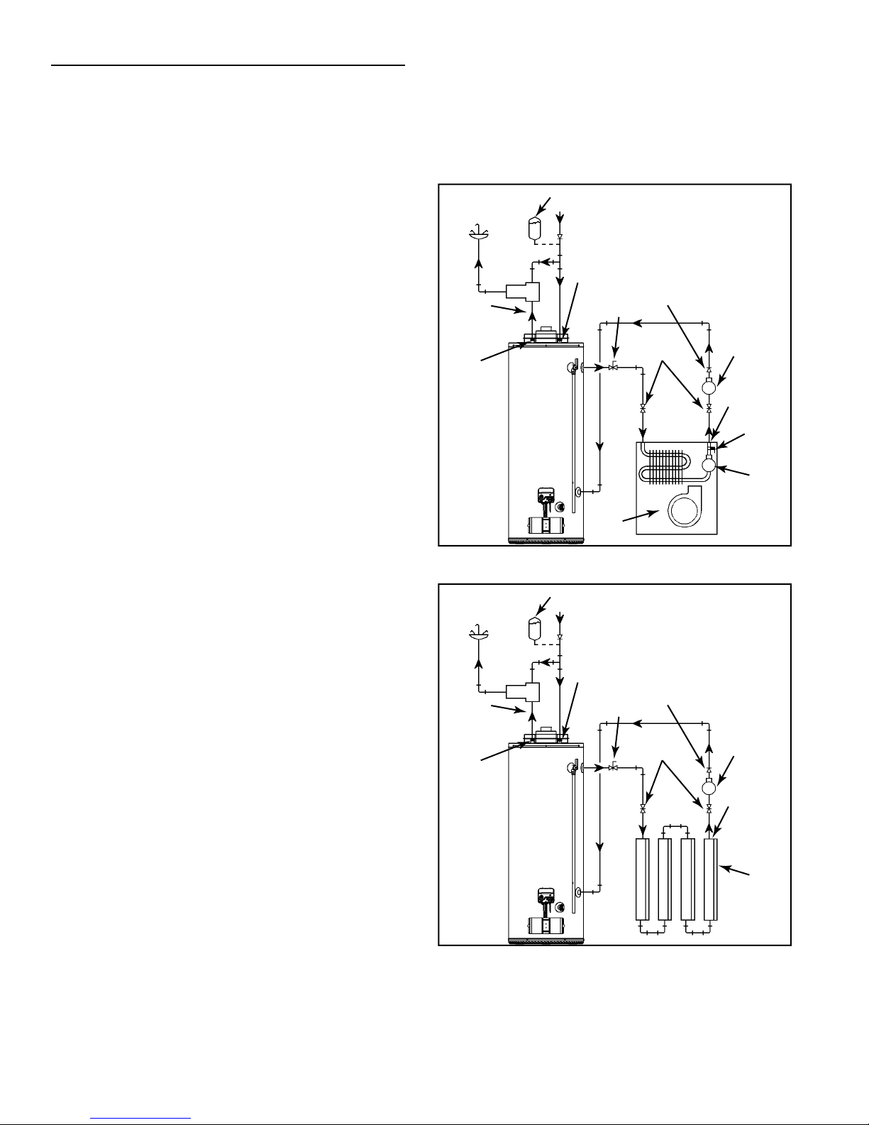
Installation
The heating mode may be one of the following options:
A. A fan coil/air handler (Figure 11).
B. A hydronic baseboard (fi nned tube) loop/In fl oor heating
(Figure 12).
The following is a list of requirements for the installation
of option A or B.
1. Install shut-off valves and unions so that the water
heater can be isolated from the heating module should
servicing of the water heater become necessary.
2. Install a drain valve at the lowest point of the heating
loop so that water can be drained from the heating
module without affecting the water heater.
3. If the air handler does not have a venting means at
the highest point of the piping arrangement, install
an air bleed at the highest point of the plumbing
arrangement.
HOT WATER
TO HOUSE
FIXTURE
8 in TO
12 in MAX.
HOT
OUTLET
EXPANSION TANK (OPTIONAL)
COLD SUPPLY
CHECK VALVE (IF USED
REQUIRES EXPANSION TANK)
MIXING
VALV E
M
C
H
WATER
HEATER
COLD INLET
FLOW
CONTROL
AIR
HANDLER
CHECK
VALV E
HOSE BIB
(OPT.)
SUPPLY
EXTERNAL
CIRCULATOR
RETURN
DRAIN/
PURGE
VALV E
INTERNAL
CIRCULATOR
Figure 11
HOT WATER
TO HOUSE
FIXTURE
8 in TO
12 in MAX.
HOT
OUTLET
EXPANSION TANK (OPTIONAL)
COLD SUPPLY
CHECK VALVE (IF USED
REQUIRES EXPANSION TANK)
MIXING
VALV E
M
C
H
WATER
HEATER
COLD INLET
FLOW
CONTROL
CHECK
VALV E
HOSE BIB
(OPT.)
SUPPLY
EXTERNAL
CIRCULATOR
RETURN
HYDRONIC
BASEBOARDS
(SERIES
CONNECTED
SHOWN)
Figure 12
www. gsw-wh .com 17

GAS PIPING
WARNING
Fire and Explosion Hazard
• Do not use water heater with
any gas other than the gas
shown on the rating plate.
• Excessive pressure to gas
control valve can cause serious
injury or death.
• Turn off gas lines during
installation.
• Contact qualified installer or
service agency.
WARNING
Explosion Hazard
Have a qualified technician make sure that the L.P.
gas operating pressure does not exceed 13" water
column.
Failure to do so can result in death, explosion, or
fire.
Make sure the gas supplied is the same type listed on the
model rating plate. The inlet gas pressure must not exceed
13 inch w.c. for natural gas and propane (LP) gas. The
minimum inlet gas pressure shown on the rating plate is
that which will permit fi ring at rated input.
All gas piping must comply with local codes and ordinances
or with the “Natural Gas and Propane Installation Code”
B149.1 . Copper or brass tubing and fi ttings (except that
which is certifi ed for gas usage) should not be used.
If the gas control valve/thermostat is subjected to
pressures exceeding 1/2 psi (14 inch w.c.), the damage
to the gas control valve/thermostat could result in a fi re or
explosion from leaking gas.
There must be:
• A readily accessible manual shut-off valve in the gas
supply line serving the water heater, and
• A sediment trap ahead of gas control valve/thermostat
to help prevent dirt and foreign materials from entering
the gas control valve/thermostat.
• A fl exible gas connector or a ground joint union between
the manual gas shut-off valve and gas control valve/
thermostat to permit servicing of the unit.
Be sure to check all the gas piping for leaks before lighting
the water heater. Use a soapy water solution, not a match
or open fl ame. Repair and retest as required. When
fi nished, rinse off soapy solution and wipe dry.
WARNING
Fire and Explosion Hazard
• Use joint compound or tape
compatible with propane.
• Leak test before operating
heater.
• Disconnect gas piping and
shut-off valve before pressure
testing system.
Use pipe joint compound or Tefl on tape marked as being
resistant to the action of gases.
The appliance and its gas connection must be leak tested
before placing the appliance in operation.
The appliance and its individual manual gas shut-off
valve should be disconnected from the gas supply piping
system during any pressure testing of that system at test
pressures in excess of 1/2 psi. It should be isolated from
the gas supply piping system by closing its individual
manual gas shut-off valve during any pressure testing of
the gas supply piping system at test pressures equal to
or less than 1/2 psi.
Connecting gas piping to the gas control valve/thermostat
of water heater can be accomplished by the method shown
in Figure 13.
If the main gas line shut-off serving all gas appliances is
used, also turn “OFF” the gas at each appliance. Leave
all gas appliances shut “OFF” until the water heater
installation is complete.
A gas line of suffi cient size must be run to the water
heater. Consult the current edition of the “Natural Gas
and Propane Installation Code” B149.1 and your gas
supplier concerning pipe size.
18 www. gsw-wh .com
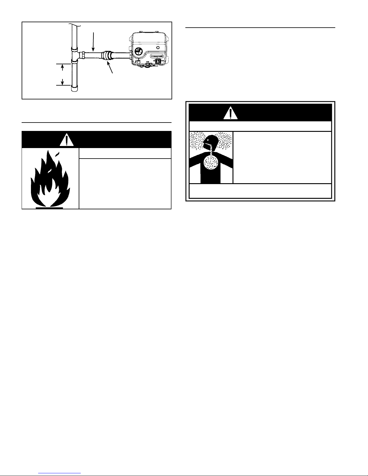
BLACK PIPE
Installations above 2,347m (7,700’). require replacement
of the burner orifice in accordance with the current
edition of the “Natural Gas and Propane Installation
Code” B149.1 . Failure to replace the orifi ce could result
in improper and ineffi cient operation of the appliance,
HIGH ALTITUDE INSTALLATIONS
76mm
(3”) MIN.
SEDIMENT
CAP
TRAP
GROUND
JOINT
UNION
(OPTIONAL)
GAS
CONTROL
VALV E
producing carbon monoxide gas in excess of safe limits,
which could result in serious personal injury or death.
Contact your gas supplier for any specifi c changes which
may be required in your area.
Figure 13
SEDIMENT TRAP
WARNING
Fire and Explosion Hazard
• Contaminants in gas lines can
cause fire or explosion.
• Clean all gas piping before
installation.
• Install sediment trap in accor-
A sediment trap should be installed as close to the inlet of
the water heater as practical at the time of water heater
installation. The sediment trap should be either a tee fi tting
with a capped nipple in the bottom outlet or other device
recognized as an effective sediment trap. If a tee fi tting is
used, it should be installed in conformance with the method
of installation shown in Figure 13.
Contaminants in the gas lines may cause improper
operation of the gas control valve/thermostat that may
result in fi re or explosion. Before attaching the gas line be
sure that all gas pipe is clean on the inside. To trap any
dirt or foreign material in the gas supply line, a sediment
trap (sometimes called a dirt leg) must be incorporated in
the piping. The sediment trap must be readily accessible.
Install in accordance with the “Gas Piping” section. Refer
to the current edition of the “Natural Gas and Propane
Installation Code” B149.1 .
dance with B149.1.
WARNING
Breathing Hazard - Carbon Monoxide Gas
• High altitude orifice must be
installed for operation above
2,347 metres (7,700 ft.).
• Contact a qualified installer or
service agency.
Breathing carbon monoxide can cause brain damage or death.
Always read and understand instruction manual.
www. gsw-wh .com 19

VENTING
This direct vent water heater uses a sealed venting
system to supply fresh combustion air to the heater and
to exhaust the products of combustion (fl ue gases) to the
outdoors. The venting is a “pipe in a pipe” system. The
inner (3”) piping carries out the exhaust fl ue gases while
the outer (6”) piping carries in fresh combustion air. The
corrugated end of the vent piping connects to the top of
the water heater and the opposite end connects to the vent
termination hood which will be mounted on the exterior wall
(see Figure 15). Figure 15 shows the hot exhaust gas exit
and the location of the combustion air intake.
Figure 18 thru Figure 25 show how to assemble and
connect the venting system.
Figure 27 thru Figure 29 show various installation options.
DO NOT STORE OR USE GASOLINE OR OTHER
FLAMMABLE VAPOURS AND LIQUIDS IN THE VICINITY
OF THE VENT TERMINATION HOOD.
WARNING
Breathing Hazard - Carbon Monoxide Gas
• Install vent system In accordance with codes.
• Do not operate water heater if flood damaged.
• Install water heater in accordance with the
instruction manual.
• Do not operate if soot buildup is present.
• Do not obstruct water heater air intake.
• Do not place chemical vapor emitting products near
water heater or vent terminal hood.
• Gas and carbon monoxide detectors are available.
• Never operate the heater unless it is vented to the
outdoors and has adequate air supply to avoid risks
of improper operation, fire, explosion or asphyxiation.
• Analyze the entire vent system to make sure that
condensate will not become trapped in a section of
vent pipe and therefore reduce the open cross
sectional area of the vent.
• Chemical corrosion of flue and vent system can
cause serious injury or death.
Breathing carbon monoxide can cause brain damage or death.
Always read and understand instruction manual.
NEVER OPERATE THE WATER HEATER UNLESS IT IS
VENTED TO THE OUTDOORS AND HAS ADEQUATE AIR
SUPPLY TO AVOID RISKS OF IMPROPER OPERATION,
FIRE, EXPLOSION OR ASPHYXIATION.
DO NOT OBSTRUCT THE FLOW OF COMBUSTION AND
VENTILATING AIR. ADEQUATE AIR FOR COMBUSTION
AND VENTILATION MUST BE PROVIDED FOR SAFE
OPERATION.
VENT TERMINAL CLEARANCES
The vent system must terminate so that proper clearances
are maintained as cited in local codes or the current edition
of the “Natural Gas and Propane Installation Code”
B149.1 as follows:
Figure 14
20 www. gsw-wh .com
FRESH
COMBUSTION
AIR IN
HOT
EXHAUST
GAS OUT
Figure 17
VENT CONNECTIONS
After the location for the vent terminal has been selected
as outlined in Figure 6 & Figure 14, use the following
illustrations for installation:
SCREW
Figure 15
Be sure venting is properly connected to prevent escape
of dangerous flue gases which could cause deadly
asphyxiation.
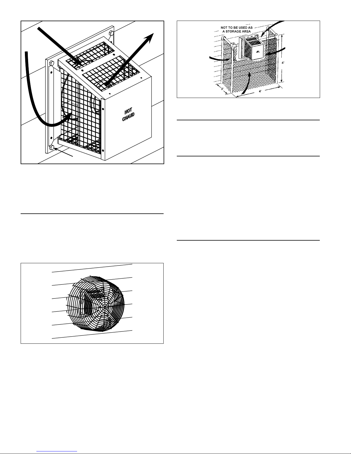
DV TERMINATION SAFETY COVER
When the heater is in operation the vent termination hood
will be hot (see Figure 15).
A Safety cover (see Figure 16) is available to prevent
accidental contact with the vent terminal. Contact your
Customer Service Department for ordering information.
LOCATING CLEARANCE HOLE FOR VENT
Cut a clearance hole, approximately 178mm (7”) in
diameter, through the exterior wall for the vent assembly.
The recommended height is 1.62m (64”) for 151l (40 gal.)
models, 1.85m (73”) for 189l (50 gal.) models and 1.88m
(74”) for 189l (50 gal.) Hi-Input models, as measured from
the hole center to bottom of water heater. Where the wall
is combustible and the wall thickness is over 356mm (14”),
25mm (1”) clearance to combustible surfaces around the
vent terminal is needed. The fi rst 356mm (14”) is zero
clearance (see Figure 20).
STANDARD VENT ARRANGEMENT
* If the horizontal length of the venting is less than 762mm
(30”) the restricter plate must be installed (see Figure 21,
Figure 27 thru Figure 29).
• Do not use the restricter plate in an offset installation
(see Figure 25).
• Do not use the restricter plate the horizontal length of
the venting is greater than 762mm (30”).
Note: The length of “unstretched” corrugated tube could
cause the length of the vent run to exceed the minimum. In
this case cut off a piece of the corrugated tube to achieve
the 432mm (17”) minimum vent length.
Figure 16
Alternatively, a wire mesh or louvered fencing guard can
be built around the termination as shown in Figure 17.
www. gsw-wh .com 21
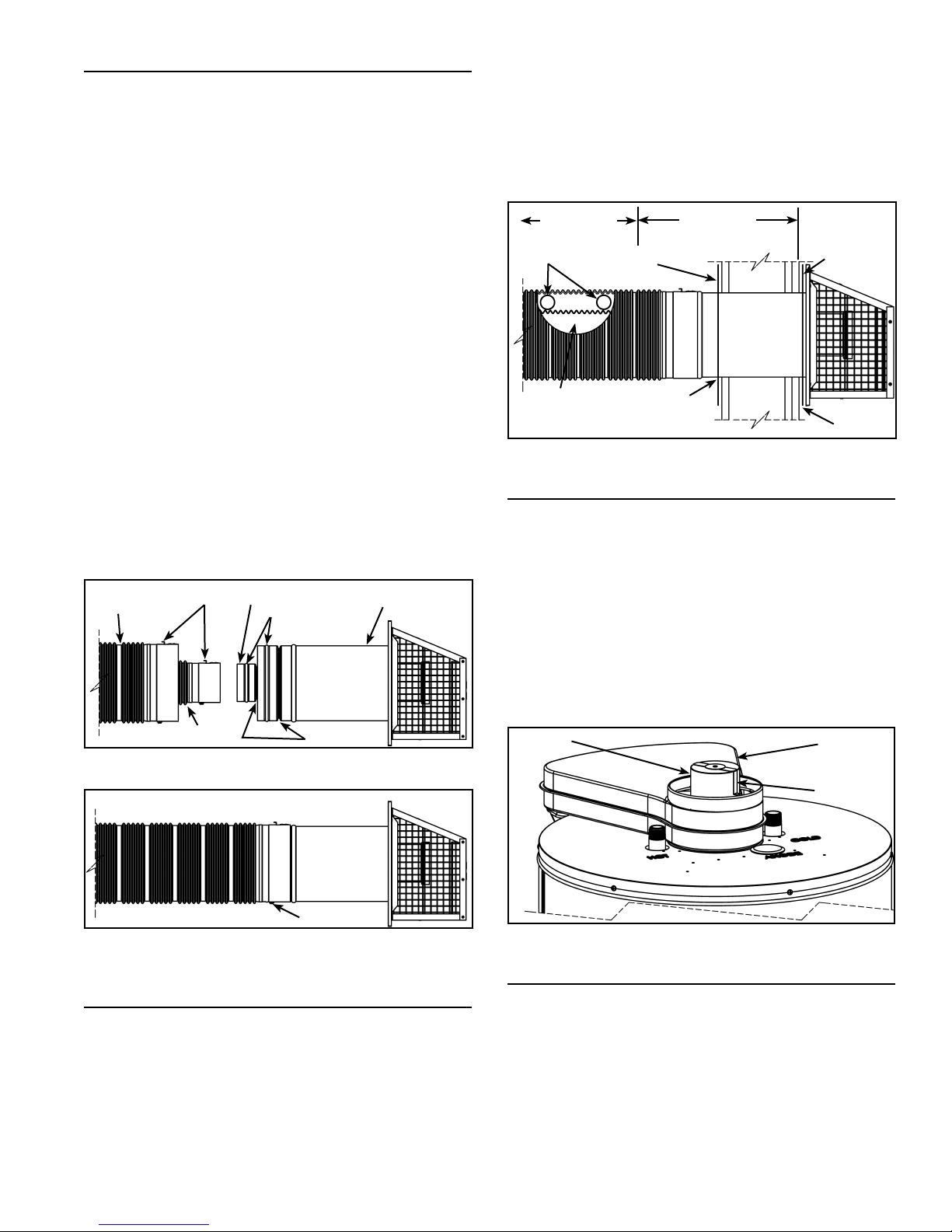
VENT ASSEMBLY
The vent piping and the vent termination hood are to be
connected as shown in Figure 19.
Maintain vent clearances to combustibles as shown in
Figure 20.
Depending on your access to where the vent termination
passes through the wall, you may wish to connect the
piping and vent termination hood together fi rst.
Inside the vent piping there are springs that hold the two
corrugated pipes in position. When the pipes are stretched
to the required length, the springs will remain properly
spaced.
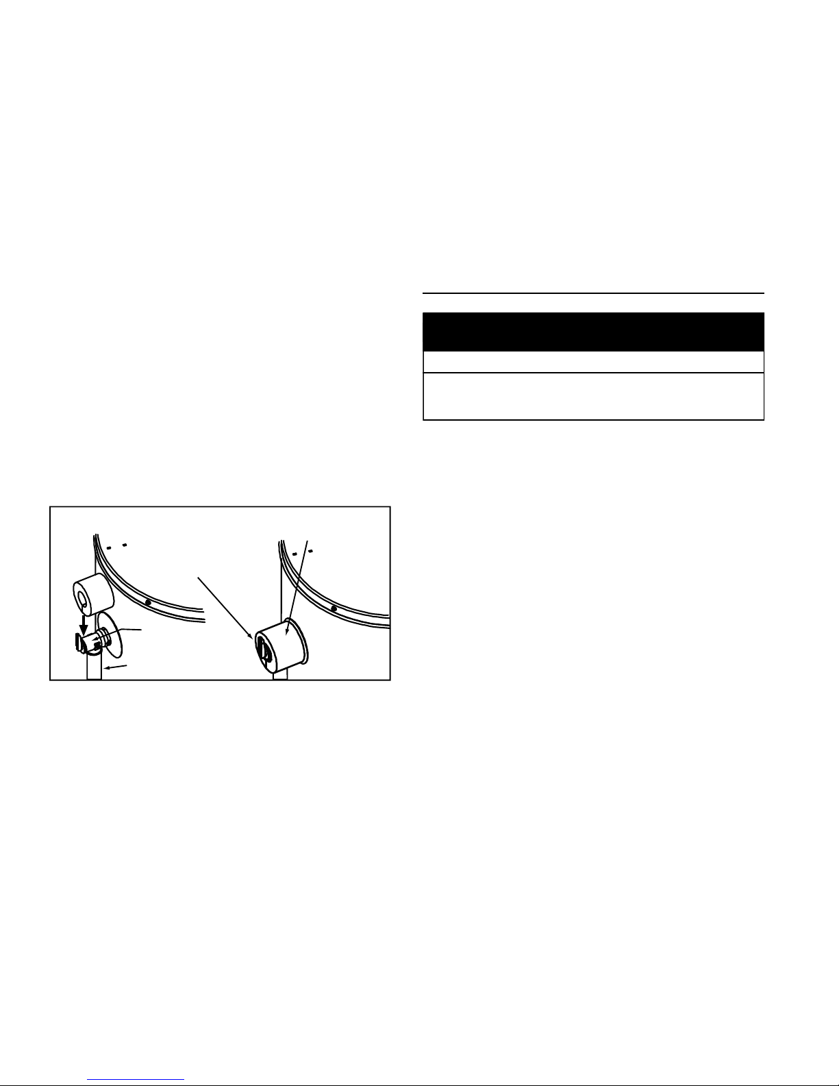
To connect the vent piping to the vent termination hood,
fi rst slide the inner (3”) corrugated pipe over the inner vent
termination pipe. Continue this action until the locking
clip on the corrugated pipe snaps into position in the
corresponding groove (see Figure 18). Secure corrugated
pipe with screw (supplied) inserted through hole opposite
the locking clip.
Repeat this process with the outer (6”) corrugated pipe and
lock it into position on the outer pipe on the vent termination
(see Figure 18). Secure corrugated pipe with screw
(supplied) inserted through hole opposite the locking clip.
Note: To reduce the friction between the corrugated pipe
and the O-rings, it is recommended to dampen the O-rings
with water.
The completed connection is shown in Figure 19.
OUTER
CORRUGATED
PIPE
LOCKING
CLIP
INNER VENT
TERMINATION PIPE
O-RING
OUTER VENT
TERMINATION PIPE
junction of the vent terminal base plate and the exterior
wall with exterior type sealant (not included). Slide the trim
plate (inside) over the outer corrugated tube and fasten the
trim plate to the interior wall. Caulk the junction of the outer
corrugated tube and the trim plate (inside) with suitable
sealant. The vent termination hood attaches to the vent
piping as shown in Figure 19.
25mm (1”)
CLEARANCE
SPRING
CUTAWAY TO
SHOW SPRING
PLACEMENT
TRIM PLATE
(INSIDE)
APPLY
SEALANT
356mm
(14”) ZERO
CLEARANCE
TRIM PLATE
(OUTSIDE)
APPLY
SEALANT
Figure 20
VENT RESTRICTER PLATE
The vent restricter plate (see Figure 21) is required for
short horizontal runs on low vent installations (see Figure
28) and high vent installations (see Figure 29).
For short horizontal vent runs (see Figure 28) place the
restricter plate over the fl ue tube reducer before connecting
the inner corrugated tube to the fl ue tube reducer. DO NOT
use the restricter plate if the horizontal run is greater than
762mm (30”).
For high vertical runs use the restricter plate only when
the vertical run of the venting above the heater is greater
than 1.21m (48”) (see Figure 29).
INNER
CORRUGATED PIPE
LOCKING CLIP
GROOVE
Figure 18
SCREW
Figure 19
SECURING VENT TERMINATION ASSEMBLY TO
THE EXTERIOR WALL
Some models are supplied with trim plates which may
be used to cover the holes in the wall (see Figure 1 and
Figure 20). Slide one trim plate (if supplied) over the outer
corrugated tube, then insert the outer corrugated tube
through the clearance hole from exterior wall. Secure
the trim plate to the exterior wall, then secure the vent
terminal to the exterior wall with 4 screw anchors (included)
appropriate for the type of wall construction. Caulk the
FLUE TUBE
REDUCER
UPPER AIR
INLET BOX
RESTRICTER
PLATE
Figure 21
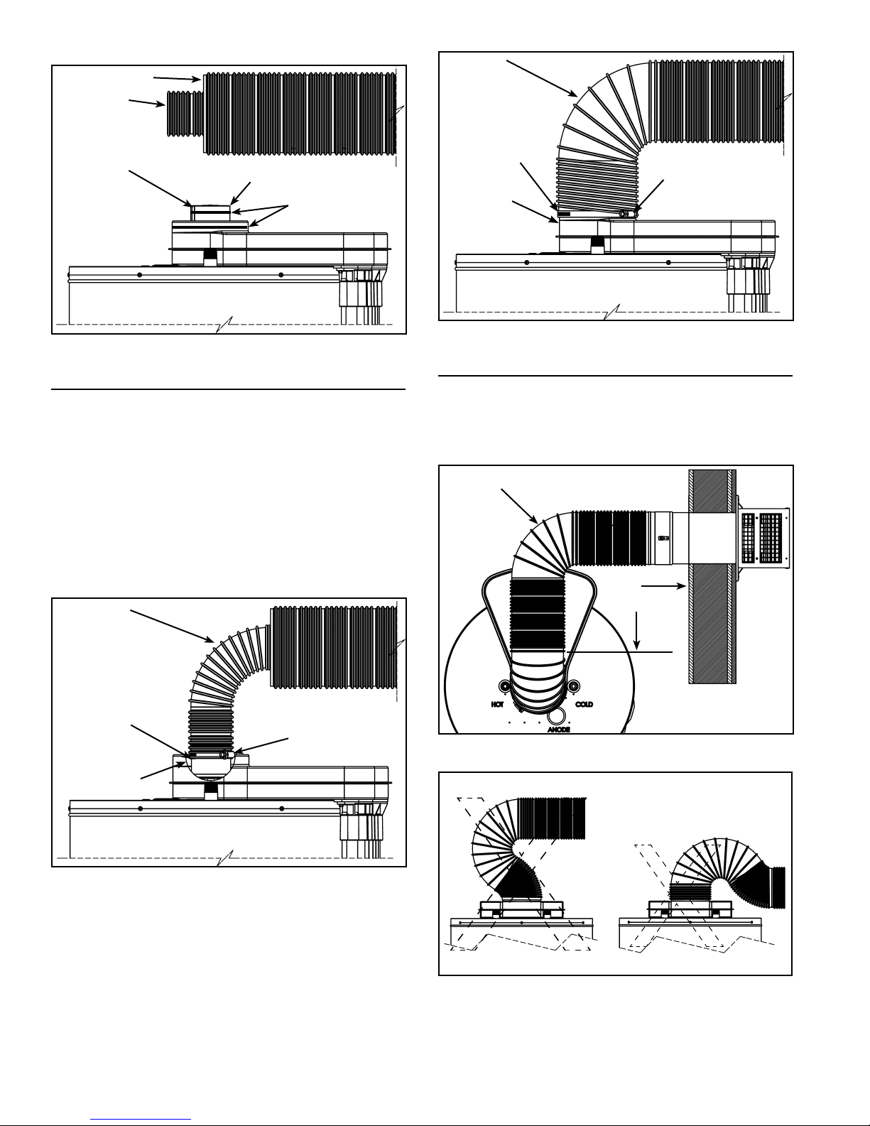
UNCOMPRESSING THE CORRUGATED TUBING
1. Pull the inner corrugated tube towards the water heater
and leave some length over the water heater’s center
for bending (see Figure 22).
2. Pull the outer corrugated tube toward the water
heater and leave it 50mm (2”) shorter than the inner
corrugated tube.
3. Make sure there are two springs evenly spaced at the
bend in the tube.
4. Use metal hangers to keep venting level or with a
slope upward from the heater to terminal.
22 www. gsw-wh .com
OUTER
CORRUGATED PIPE
INNER
CORRUGATED
PIPE
RESTRICTER
PLATE
FLUE TUBE
REDUCER
APPLY
SILICONE
SMOOTH,
EASY CURVE
APPLY
SILICONE
TO AIRBOX
BEFORE
ATTACHING
PIPING
SECURE
WITH A
SHEET METAL
SCREW
GEAR
CLAMP
Figure 22
VENT CONNECTION TO THE WATER HEATER
Bend both the corrugated pipes toward the fl ue connection
on the water heater. Pull and connect the inner corrugated
pipe to the water heater’s fl ue tube reducer with hi-temp
red silicone (included) and gear clamp. Make sure this
connection is tight and leak proof (see Figure 23).
*The sealant between the inner corrugated pipe and water
heater’s fl ue tube reducer must be hi-temp red silicone
or other material suitable for 315°C (600°F) continuous
service.
Note: If you are using the vent restricter plate, the inner
vent pipe is to go over the side legs and down the stops.
SMOOTH,
EASY CURVE
RESTRICTER
PLATE STOP
GEAR
CLAMP
Figure 24
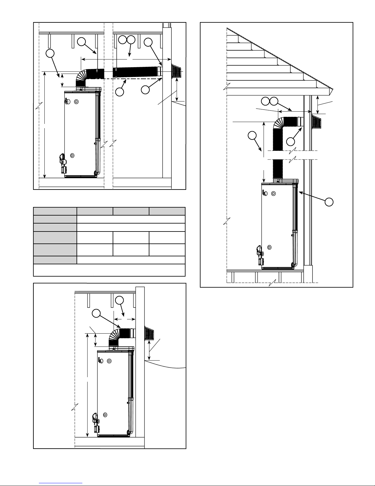
OFFSET VENT ARRANGEMENT
Where a straight vent arrangement is impossible, a
horizontal 90° maximum bend can be made. Use the
water heater casing outer diameter as a template to form
the corrugated tube.
SMOOTH,
EASY CURVE
90°
MAXIMUM
BEND
Figure 25
CUTAWAY TO
SHOW DETAILS
Figure 23
Apply hi-temp red silicone (included) around the collar on
air manifold box. Pull the outer corrugated pipe all the way
on to collar and secure with the gear clamp. Pull the free
end of the corrugated pipe past the gear clamp and secure
with one sheet metal screw (see Figure 24).
www. gsw-wh .com 23
Figure 26
Note: To ensure good exhaust gas fl ow, bend vent piping
using a smooth, easy curve as shown in Figure 23 thru
Figure 25. Do not use reverse or compound curves as
shown in Figure 26.
Low Vent installation
9
High Vent installation
1
5
6
1
A
B
7
C
8
ABOVE
ANTICIPATED
SNOW LEVEL
OR 305mm
(12”) ABOVE
GRADE
Figure 27
DIM. 4038 5040 5047
A 2.03m (80”) MAX.
B 228mm (9”) MIN.
C
(RECOMMENDED)
C
(MINIMUM)
D 362mm (14.25”) MIN.
NOTE: Dimension “C” is the height above to fl oor to the center of the
termination hole through the exterior wall.
1.62m (63.63”) 1.85m (73.00”) 1.88m (74.00”)
1.54 (60.75) 1.75 (69.50) 1.79 (70.50)
432mm
(17”)
MIN.
1
1.83m
(72”)
MAX.
51
305mm
(12”) MIN.
BELOW
SOFFIT
6
2
Minimum Vent installation
3
228mm
(9”)
C
Figure 28
Figure 29
4
NOTES: (applies to Figure 27 thru Figure 29)
1. In any installation the total of dimension “A” plus
ABOVE
D
ANTICIPATED
SNOW LEVEL
OR 305mm
(12”) ABOVE
GRADE
dimension “B” must not exceed 2.26m (89”).
2. This heater can be installed with 0mm (0”) clearance
to a wall.
3. Minimum vent pipe clearance to combustibles is 25mm
(1”) (see Figure 20).
4. Minimum distance from center of heater to wall is
362mm (14.25”).
5. Dimension “A” includes wall thickness.
6. Hole diameter in wall is 178mm (7”).
7. Venting must slope up away from the heater a
minimum of 6.4mm per 305mm (0.25” per foot) of
length to prevent condensation from collecting
and to provide suffi cient draft.
8. Distance above horizontal at full extension is 50mm
(2”).
9. Use support stays to hold the venting to avoid sags
or valleys.
24 www. gsw-wh .com

INSTALLATION CHECKLIST
Note: Use and complete this checklist before lighting the
heater. Correct any conditions that do not meet these
instructions.
Water Heater Location
Centrally located with the water piping system.
Located as close to gas piping and vent pipe system
as possible.
Located indoors and in a vertical position. Protected
from freezing temperatures.
Proper clearances from combustible surfaces
maintained and not installed directly on a carpeted
floor.
Provisions made to protect the area from water
damage. Metal drain pan installed and piped to an
adequate drain.
Installation area free of corrosive elements, flammable
material and flammable vapour emitting products.
Sufficient room to service the water heater.
Gas Supply and Piping
Gas supply is the same type as listed on the water
heater data plate.
Gas line equipped with shut-off valve, union and
sediment trap.
Adequate pipe size and of approved material.
Approved pipe joint compound or tape used.
Chloride-free soap and water solution or other
approved means used to check all connections and
fittings for possible gas leaks.
Vent Termination Hood
Securely fastened to exterior wall.
Above anticipated snow level or 305mm (12”) above
grade.
Proper clearances from windows, doors, corners,
other vent openings etc.
Area around vent termination hood clear and
unobstructed.
No flammable vapour emitting products stored nearby.
Safety covers in place (when applicable).
Water System Piping
Temperature-Pressure relief valve properly installed
with a discharge line run to an open drain and
protected from freezing.
All piping properly installed and free of leaks.
Heater completely filled with water.
Closed system pressure build-up precautions installed.
Mixing valve installed (when applicable).
After all actions on checklist are checked/
completed, read the Lighting Instructions and
proceed with lighting the heater.
Vent Pipe System
Evenly stretched out between water heater and vent
termination hood.
Smooth bend with adequate support to prevent
sagging, 6.4mm per 305mm (0.25” per foot).
Inside pipe (3”) and outside pipe (6”) securely
fastened to vent termination hood.
Vent restricter plate installed on heater flue outlet as
applicable.
Inside pipe (3”) and outside pipe (6”) securely fastened
to water heater with silicone and gear clamps.
Not obstructed in any way.
www. gsw-wh .com 25
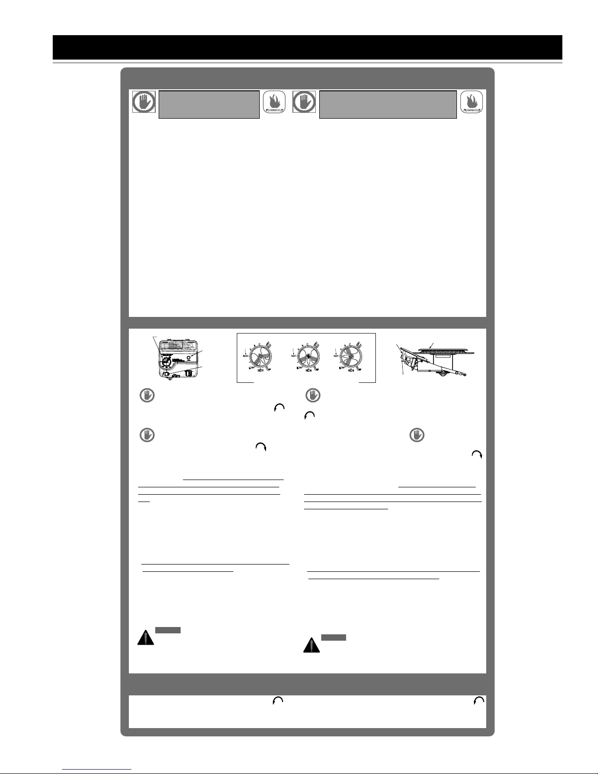
LIGHTING INSTRUCTIONS
FOR YOUR SAFETY READ
BEFORE LIGHTING
WARNING: If you do not follow these
instructions exactly, a fire or explosion
may result causing property damage,
personal injury or loss of life.
BEFORE LIGHTING: ENTIRE SYSTEM MUST BE FILLED
WITH WATER AND AIR PURGED FROM ALL LINES
A. This appliance has a pilot which is lit by a piezoelectric
spark gas ignition system. Do not open the inner door of the
appliance and try to light the pilot by hand.
B. BEFORE LIGHTING smell all around the appliance area for
gas. Be sure to smell next to the floor because some gas is
heavier than air and will settle on the floor.
WHAT TO DO IF YOU SMELL GAS
• Do not try to light any appliance.
• Do not touch any electric switch; do not use any phone in
your building.
• Immediately call your gas supplier from a neighbor's
phone. Follow the gas supplier's instructions.
• If you cannot reach your gas supplier, call the fire
department.
C. Use only your hand to push in or turn the gas control knob.
Never use tools. If the knob will not push in or turn by hand,
don't try to repair it, call a qualif ied service technician. Force
or attempted repair may result in a fire or explosion.
D. Do not use this appliance if any part has been under water.
Immediately contact a qualified installer or service agency to
replace a flooded water heater. Do not attempt to repair the
unit! It must be replaced!
LIGHTING INSTRUCTIONS
Gas Control & Temperature Knob /
Bouton réglage du gaz & temp.
GAS CONTROL / COMMANDE DU GAZ
1. STOP! It is imperative that you read all safety warnings
before lighting the pilot.
2. Turn the gas control/temperature knob counterclockwise to
the "OFF" position.
3. Wait ten (10) minutes to clear out any gas. If you then smell gas,
STOP! Follow “ B” in the safety information above on
this label. If you do not smell gas, go to the next step.
4. Turn the gas control/temperature knob clockwise to
“PILOT”. See Figure ‘B’.
5. Press the gas control/temperature knob all the way in and hold
it in. The knob should travel in about 6mm (1/4 inch) if it is set to
"PILOT" correctly. While holding the gas control/temperature
knob in, click the igniter button continuously (about once a
second) for up to 90 seconds or until Status Light begins to
blink. The pilot flame should envelop the thermopile. See Figure
‘D’.
6. When the status light starts blinking, release the gas
control/temperature knob. Set the gas control/temperature knob
to the desired setting. See Figure ‘C’.
• If the status light does not start blinking within 90 seconds,
repeat steps 2 through 5 up to THREE (3) times, waiting 10
minutes between lighting attempts.
• The circuitry in this advanced gas valve requires that you wait
10 minutes between lighting attempts.
• If the status light turns a solid color, release the gas
control/temperature knob and repeat steps 2 through 5
(waiting 10 minutes before attempting to relight the pilot). If
the status light does not start blinking after three lighting
attempts, turn the gas control/temperature knob to the "OFF"
position and call a qualified service technician or your gas
supplier.
DANGER:
DANGER: Hotter water increases the risk of scald injury.
Consult the instruction manual before changing the
temperature setting.
Refer to the Lighting Instructions in the Installation Manual for
more detailed troubleshooting information.
Status
Light /
Témoin
lumineux
Igniter
Button /
Bouton
allumeur
FIGURE 'A'
Repère
120°F
Mark
"OFF" POSITION
POSITION "OFF"
CONTROL KNOB / BOUTON DE RÉGLAGE DU GAZ
TO TURN OFF GAS TO APPLIANCE
1. Turn the gas control/temperature knob counterclockwise
to the "OFF" position. The status light will stop blinking and
stay on for a short time after the water heater is turned off.
See Figure ‘A’.
POUR VOTRE SÉCURITÉ, LISEZ
ATTENTIVEMENT AVANT L’ALLUMAGE
AVERTISSEMENT: Tout manquement aux présentes
directives peut causer un incendie ou une explosion
FLAMMABLE
entraînant des dommages matériels, des blessures ou la
mort.
AVANT L’ALLUMAGE: LE RÉSEAU D’ALIMENTATION EN EAU DOIT
ÊTRE ENTIÈREMENT REMPLI D’EAU ET L’AIR ENTIÈREMENT PURGÉ
A. L’allumage de la veilleuse de cet appareil au gaz est assuré par un système
d’allumage piézoélectrique à étincelles. Ne tentez pas d’ouvrir la porte
d’accès interne et d’allumer la veilleuse manuellement.
B. AVANT L’ALLUMAGE, humez l’air tout autour de l’appareil afin d’y déceler
une éventuelle odeur de gaz. Humez aussi l'air près du sol, car certains gaz
sont plus lourds que l’air et s’y accumulent.
SI VOUS DÉTECTEZ UNE ODEUR DE GA Z
• Ne mettez aucun appareil en marche.
• Ne touchez à aucun interrupteur; ne vous servez pas des téléphones se
trouvant dans le bâtiment.
• Appelez immédiatement votre fournisseur de service de gaz à partir du
téléphone d’un voisin et suivez ses directives.
• Si vous ne pouvez communiquer avec votre fournisseur de service de gaz,
appelez le service des incendies.
C. Le bouton de réglage du gaz ne doit être enfoncé ou tourné qu’à la main;
n’utilisez jamais d’outil. Si le bouton reste coincé, ne tentez pas une
réparation; appelez plutôt un technicien d'entretien qualifié. Si vous forcez
ou tentez de réparer le bouton, il a risque d’explosion ou d’incendie.
D. N’utilisez pas cet appareil même s’il n’a été que partiellement submergé par
de l’eau. Communiquez immédiatement avec un installateur qualifié ou un
centre de service afin de faire remplacer tout chauffe-eau ayant été
submergé lors d’une inondation. Ne tentez jamais de réparer l’appareil! Il
doit être remplacé!
DIRECTIVES D'ALLUMAGE
FIGURE 'B'
Repère
120°F
Mark
"PILOT" POSITION
POSITION "PILOT"
1. ARRÊTEZ! Il est essentiel de lire attentivement tous les messages
2. Tournez le bouton de réglage du gaz/température dans le sens antihoraire
jusqu'à la position "OFF".
3. Afin de laisser se dissiper tout gaz ayant pu s'accumuler, attendez dix (10)
minutes. Si vous détectez une odeur de gaz, ARRÊTEZ! Suivez la
directive de sécurité "B" au haut de cette étiquette. Si vous ne
détectez pas d’odeur de gaz, procédez à la prochaine étape.
4. Tournez le bouton de réglage du gaz/température dans le sens horaire
jusqu'à la position "PILOT" (Figure B).
5. Appuyez complètement sur le bouton de réglage du gaz/température et
maintenez-le enfoncé. Le bouton peut s'enfoncer d'environ 6 mm (1/4 po),
lorsqu'il est bien positionné à "PILOT". Tout en maintenant le bouton de
réglage du gaz/température enfoncé, appuyez de façon répétitive (une fois
par seconde) sur le bouton de l'allumeur (jusqu'à 90 secondes), ou jusqu'à
ce que le témoin lumineux s'allume. La flamme de la veilleuse devrait
envelopper la thermopile. Voir figure "D".
6. Lorsque le témoin lumineux se met à clignoter, relâchez le bouton de
réglage du gaz/température. Réglez le bouton à la position désirée (Figure
C).
• Si le témoin lumineux ne se met pas à clignoter en moins de 90 secondes,
reprenez les étapes 2 à 5 jusqu'à TROIS (3) reprises, en prenant une
pause de 10 minutes entre chaque essai d'allumage.
• Le processeur sophistiqué de cette commande du gaz force une période
d'attente de 10 minutes entre chaque essai d'allumage.
• Si le témoin lumineux passe au une couleur unie continue, relâchez le
bouton de réglage du gaz/température et reprenez les étapes 2 à 5, en
prenant une pause de 10 minutes entre chaque essai d'allumage. Si le
témoin lumineux ne se met pas à clignoter en trois essais d'allumage,
ramenez le bouton de réglage du gaz/température à la position "OFF" et
faites appel à un technicien d'entretien qualifié ou à votre fournisseur du
gaz.
Reportez-vous aux Directives d'allumage du manuel d'installation pour des
instructions de dépannage plus détaillées.
FIGURE 'C'
Repère
120°F
Mark
"ON" POSITION
POSITION "ON"
d’avertissement avant d’allumer la veilleuse.
DANGER:
DANGER: Plus l’eau est chaude, plus le risque d’ébouillantage est
élevé. Consultez les directives du manuel à ce sujet avant de régler
la température.
Pilot Flame /
Flamme de la veilleuse
Thermopile
FIGURE 'D'
COUPER L’ALIMENTATION
EN GAZ DE L’APPAREIL
1. Tournez le bouton de réglage du gaz/température dans le sens antihoraire
jusqu'à la position "OFF". Le témoin lumineux cesse de clignoter et reste
allumé un court moment après l'arrêt du chauffe-eau (Figure A).
FLAMMABLE
Main Burner / Brûleur
329353-000
26 www. gsw-wh .com
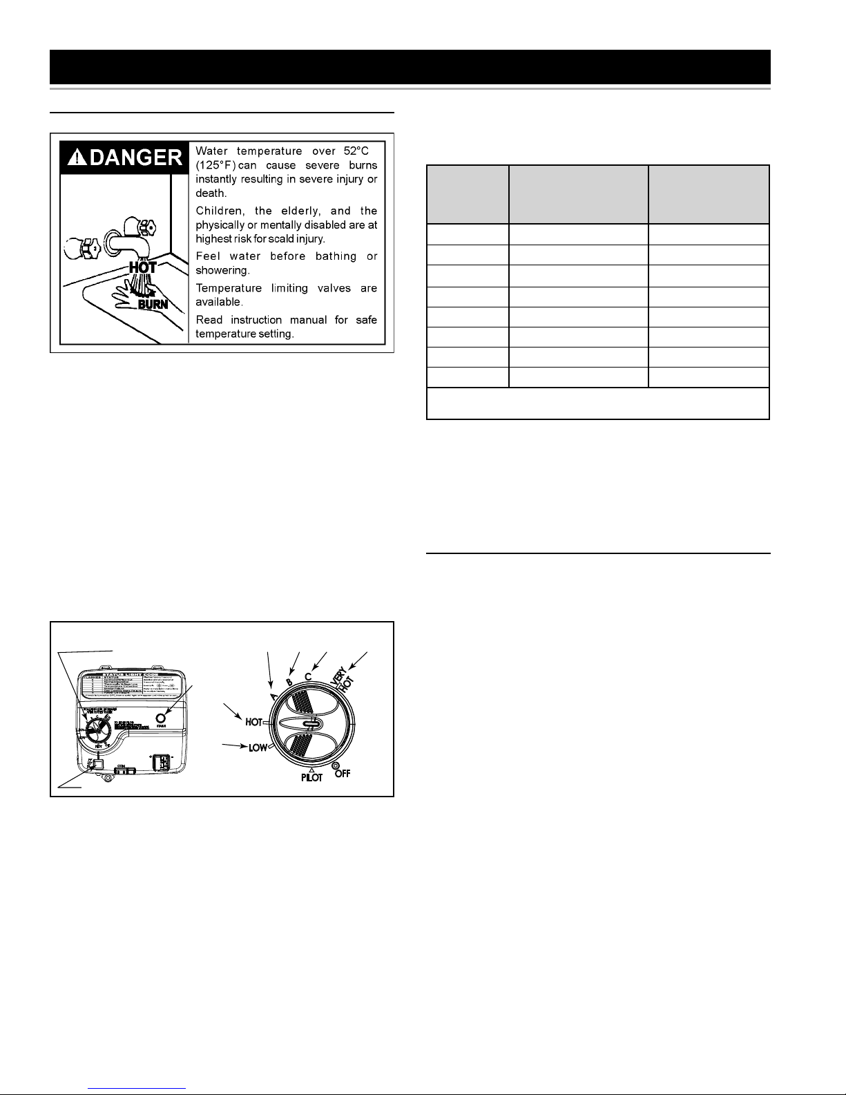
TEMPERATURE REGULATION
TEMPERATURE REGULATION
Temperature Adjustment
Valves for reducing the point-of-use temperature by mixing
cold and hot water are available (see Figure 8). Also
available are inexpensive devices that attach to faucets to
limit hot water temperatures. Contact a licensed plumber
or the local plumbing authority.
Note: During low demand periods, a lower thermostat
setting will reduce energy losses and may satisfy your
normal hot water needs. If hot water use is expected to
be more than normal, a higher thermostat setting may be
required to meet the increased demand. When leaving
your home for extended periods (e.g., vacations etc.) turn
the temperature dial to its lowest setting. This will maintain
the water at low temperatures with minimum energy losses
and prevent the tank from freezing during cold weather.
GAS CONTROL VALVE/THERMOSTAT
SETTINGS
GAS CONTROL/
TEMPERATURE KNOB
IGNITER
STATUS
LIGHT
49°C
(120°F)
MARK
33°C
(91°F)
MARK
55°C
(130°F)
MARK
(140°F)
MARK
(150°F)
MARK
(155°F)
MARK
68°C
65°C
60°C
Figure 30
The thermostat is adjusted to the “OFF” position when
it is shipped from the factory. Water temperature can be
regulated by moving the temperature dial to the preferred
setting. The preferred starting point is 49°C (120°F) at
the “HOT” setting. Align the knob with the desired water
temperature as shown in Figure 30. There is a hot water
scald potential if the thermostat is set too high.
Note: Temperatures shown on the gas control valve/
thermostat are approximates. The actual temperature of
the heated water may vary.
Important: Adjusting the thermostat past the 49°C (120°F)
mark on the temperature dial will increase the risk of scald
injury. Hot water can produce fi rst degree burns within:
Water
Temperature
°C (°F)
44 (110) (normal shower temp.)
47 (116) (pain threshold)
47 (116) 35 minutes 45 minutes
50 (122) 1 minute 5 minutes
55 (131) 5 seconds 25 seconds
60 (140) 2 seconds 5 seconds
65 (149) 1 second 2 seconds
68 (154) instantaneous 1 seconds
(U.S. Government Memorandum, C.P.S.C., Peter L. Armstrong,
Sept. 15,1978)
Time for 1st
Degree Burns
(Less Severe Burns)
Time for Permanent
Burns 2nd & 3rd
Degree (Most
Severe Burns)
Table 2
Should overheating occur or the gas supply fail to shut off,
turn “OFF” the manual gas shut-off valve to the appliance
(see Figure 1, item 18).
OPERATING THE TEMPERATURE CONTROL
SYSTEM
Water Temperature Adjustment
The water temperature setting can be adjusted from
33°C (91°F) to 68°C (155°F). Turn the Gas Control Valve/
Temperature Knob to the desired setting/temperature.
Note: The temperatures indicated are approximates. The
actual temperature of the heated water may vary.
Operating Modes And Settings
Standard Mode - The controller adjusts the water heater
to maintain the temperature set by the user.
Setting for vacation - The “LOW” position sets the
controller at approximately 33°C (91°F). This setting is
recommended for times when the water heater will not be
in use for an extended period of time. It effectively turns
the controller temperature setting down to a temperature
that prevents the water in the water heater from freezing
while still conserving energy.
www. gsw-wh .com 27
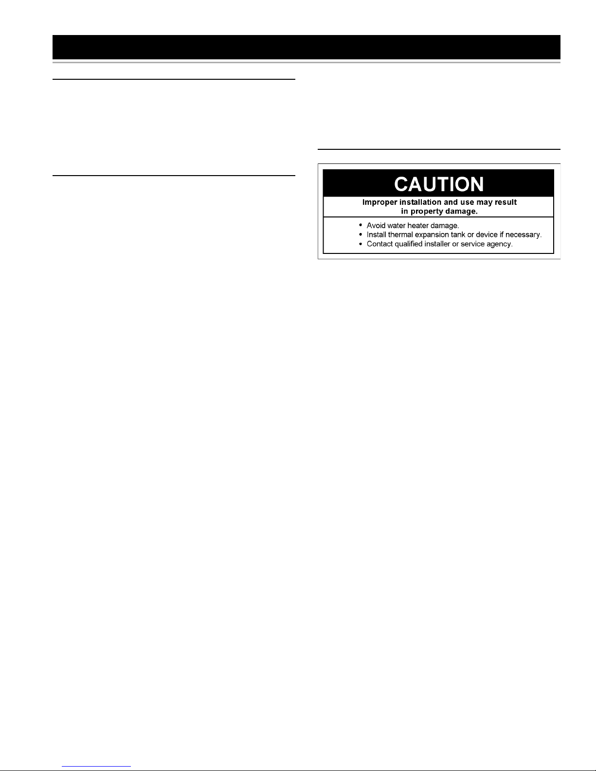
FOR YOUR INFORMATION
EXTERNAL DAMAGE
Do not operate the water heater until it has been fully
checked out by a qualifi ed technician, if the water heater:
• Has been exposed to fi re or damage.
• Displays evidence of sooting.
• Produces steam or unusually hot water.
If the water heater has been fl ooded it must be replaced.
START UP CONDITIONS
NEVER OPERATE THE HEATER WITHOUT FIRST
BEING CERTAIN IT IS FILLED WITH WATER AND A
TEMPERATURE AND PRESSURE RELIEF VALVE IS
INSTALLED IN THE RELIEF VALVE OPENING OF THE
HEATER. DO NOT ATTEMPT TO OPERATE HEATER
WITH COLD WATER INLET VALVE CLOSED.
Condensate
Whenever the water heater is fi lled with cold water, some
condensate will form while the burner is on. A water
heater may appear to be leaking when in fact the water is
condensate. This usually happens when:
a. A new water heater is fi lled with cold water for the
fi rst time.
b. Burning gas produces water vapour in water heaters,
particularly high efficiency models where flue
temperatures are lower.
c. Large amounts of hot water are used in a short time
and the refi ll water in the tank is very cold.
Moisture from the products of combustion condense on
the cooler tank surfaces and form drops of water which
may fall onto the burner or other hot surfaces to produce
a “sizzling” or “frying” noise.
Because of the suddenness and amount of water,
condensate water may be diagnosed as a “tank leak”.
After the water in the tank warms up (about 1-2 hours),
the condition should disappear.
Smoke/Odour
It is not uncommon to experience a small amount of
smoke and odour during the initial start-up. This is due to
burning off of oil from metal parts, and will disappear in
a short while.
THERMAL EXPANSION
Water supply systems may, because of such events as
high line pressure, frequent cut-offs, the effects of water
hammer among others, have installed devices such
as pressure reducing valves, check valves, back fl ow
preventers, etc. to control these types of problems. When
these devices are not equipped with an internal by-pass,
and no other measures are taken, the devices cause the
water system to be closed. As water is heated, it expands
(thermal expansion) and closed systems do not allow for
the expansion of heated water.
As water is heated, it expands (thermal expansion). As the
volume of water increases, there will be a corresponding
increase in water pressure due to thermal expansion.
Thermal expansion can cause premature tank failure
(leakage). This type of failure is not covered under the
limited warranty. Thermal expansion can also cause
intermittent temperature-pressure relief valve operation:
water discharged from the valve due to excessive pressure
build up. The temperature-pressure relief valve is not
intended for the constant relief of thermal expansion. This
condition is not covered under the limited warranty.
Do not assume the water heater is leaking until there has
been enough time for the water in the tank to warm up.
An undersized water heater will cause more condensation.
The water heater must be sized properly to meet the
family’s demands for hot water including dishwashers,
washing machines and shower heads.
Excessive condensate may be noticed during the
winter and early spring months when incoming water
temperatures are at their lowest.
Good venting is essential for a gas fi red water heater
to operate properly as well as to carry away products of
combustion and water vapour.
28 www. gsw-wh .com
A properly-sized thermal expansion tank should be
installed on all closed systems to control the harmful
effects of thermal expansion. Contact a plumbing service
agency or your retail supplier regarding the installation of
a thermal expansion tank.
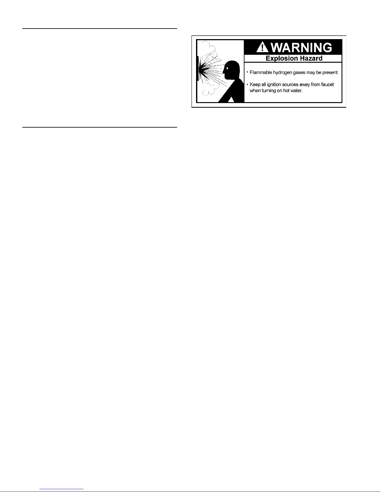
STRANGE SOUNDS
Possible noises due to expansion and contraction of some
metal parts during periods of heat-up and cool-down do
not necessarily represent harmful or dangerous conditions.
Condensation causes sizzling and popping within the
burner area during heating and cooling periods and should
be considered normal. See “Condensate” in this section.
Sediment collecting over time in the bottom of the tank
can result in “rumbling” or “percolating” sounds. Follow
the directions given in “Draining, Refi lling And Flushing”.
OPERATIONAL CONDITIONS
Smelly Water
In each water heater there is installed at least one anode
rod (see Figure 1, item 22) for corrosion protection of the
tank. Some models will have an additional anode which
is connected to the hot water outlet nipple (see Figure 1,
item 23). Certain water conditions will cause a reaction
between the anode rod and the water. The most common
complaint associated with the anode rod is one of a “rotten
egg smell” in the hot water. The smell is a result of four
factors which must all be present for the odour to develop:
“Air” In Hot Water Faucets
HYDROGEN GAS: Hydrogen gas can be produced in
a hot water system that has not been used for a long
period of time (generally two weeks or more). Hydrogen
gas is extremely fl ammable and explosive. To prevent the
possibility of injury under these conditions, we recommend
the hot water faucet, located farthest away, be opened for
several minutes before any electrical appliances which
are connected to the hot water system are used (such
as a dishwasher or washing machine). If hydrogen gas is
present, there will probably be an unusual sound similar
to air escaping through the pipe as the hot water faucet
is opened. There must be no smoking or open fl ame near
the faucet at the time it is open.
1. A concentration of sulfate in the supply water.
2. Little or no dissolved oxygen in the water.
3. A sulfate reducing bacteria which has accumulated
within the water heater (this harmless bacteria is
nontoxic to humans).
4. An excess of active hydrogen in the tank. This is
caused by the corrosion protective action of the anode.
For certain water conditions, setting the gas control valve/
thermostat at 60°C (140°F) can reduce the smell generated
in the water heater.
Note: Under these conditions install a mixing valve to limit
the temperature of the water delivered to the system (see
“Water Piping” section).
Smelly water may be eliminated or reduced in some water
heater models by replacing the anode(s) with one of less
active material, and then chlorinating the water heater tank
and all water lines. Contact the local water heater supplier
or service agency for further information concerning an
Anode Replacement Kit and this chlorination treatment.
If the smelly water persists after the anode replacement
and chlorination treatment, we can only suggest that
chlorination or aeration of the water supply be considered
to eliminate the water problem.
High Water Temperature Shut Off System
This water heater is equipped with an automatic gas
shut-off system. This system works when high water
temperatures are present. Turn “OFF” the entire gas supply
to the water heater. The high temperature shut-off is built
into the gas control valve. It is non-resettable. If the high
temperature shut-off activates, the gas control valve must
be replaced. Contact your gas supplier or service agency.
Do not remove the anode leaving the tank unprotected. By
doing so, all warranty on the water heater tank is voided.
www. gsw-wh .com 29
 Loading...