

GSW 73992 User Manual
GSW WATER HEATING
599 Hill Street West
Fergus, ON, Canada N1M 2X1
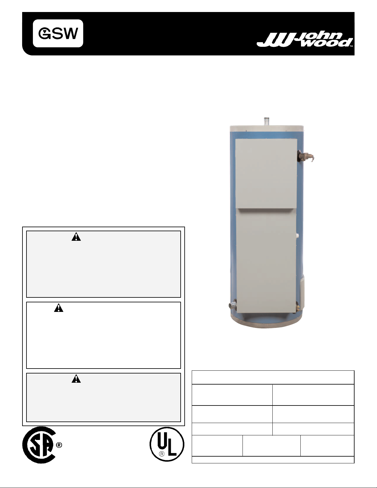
COMMERCIAL ELECTRIC WATER HEATER
INSTALLATION AND OPERATING INSTRUCTIONS
Read and understand these instructions thoroughly before attempting
any installation or service.
TABLE OF CONTENTS
I) Introduction . . . . . . . . . . . . . . . . . . . . . . . . . . . .2
II) Component Identification . . . . . . . . . . . . . . . . . .3
III) Recovery Rates . . . . . . . . . . . . . . . . . . . . . . . . .4
IV) Installation . . . . . . . . . . . . . . . . . . . . . . . . . . . .5-9
V) Electrical . . . . . . . . . . . . . . . . . . . . . . . . . . .10-17
VI) Operation . . . . . . . . . . . . . . . . . . . . . . . . . . . . .18
VII) Maintenance . . . . . . . . . . . . . . . . . . . . . . . .19-21
VIII) Leakage Checkpoints . . . . . . . . . . . . . . . . . . . .22
IX) Floor Sealing . . . . . . . . . . . . . . . . . . . . . . . . . .23
Warranty . . . . . . . . . . . . . . . . . . . . . . . . . . . . . .24
PLEASE RETAIN THESE INSTRUCTIONS IN A
SAFE LOCATION FOR FUTURE REFERENCE
WARNING:
Improper installation, adjustment, alteration, service, or maintenance can cause
injury or property damage. Refer to this
manual. For assistance or additional information, consult a qualified installer, service agency, or the electric utility.
FOR YOUR SAFETY
• Do not store or use gasoline or other
flammable vapors and liquids in the
vicinity of this or any other appliance.
• Installation and service must be performed by a qualified installer, service
agency or the electric utility.
WARNING:
If the information in these instructions is
not followed exactly, a fire or explosion
may result causing property damage, personal injury or death.
This water heater is protected by a three (3) year warranty against
leaks plus a one (1) year warranty on parts.
Record key data here for future reference and prompt service:
Installed By / Purchased From:
Installation Date:
Model Number
INSTALLATION RECORD
Location of Electrical Switch
or Circuit Protector:
Serial Number
All models are listed
by Underwriters’
Laboratories, Inc.
GSW Water Heating is a division of GSW Water Products Inc.
Volts
Watts/Element
Technical Support Line: 1-888-479-8324
Number of Elements
Volume
PART NO. 73992 REV. A (05-03)
Watts-Total
Your safety and the safety of others is very important.
We have provided many important safety messages in this manual and on your appliance.
Always read and obey all safety messages.
This is the safety alert symbol.
This symbol alerts you to potential hazards that can kill or hurt you and others.
All safety messages will follow the safety alert symbol and either the word
“DANGER” or “WARNING”.
DANGER
You can be killed or seriously injured if you don’t immediately follow
instructions.
WARNING
You can be killed or seriously injured if you don’t follow instructions.
All safety messages will tell you what the potential hazard is, tell you how to reduce the
chance of injury, and tell you what can happen if the instructions are not followed.
I) INTRODUCTION
Thank you for purchasing this water heater. Properly
installed and maintained, it will provide years of trouble free
service. This manual gives instructions for the proper installation, safe operation and maintenance of this water heater.
It is your responsibility to ensure that your water heater is
properly installed and cared for.
Important Consumer Notice
The warranty on this water heater is in effect only when the
water heater is installed and operated in accordance with
these instructions. The manufacturer of this water heater
will not assume any liability for any injury or property damage resulting from failure to comply with these instructions.
Protect your warranty: Regularly maintain your water
heater as detailed in the service and maintenance section
of this manual.
Installation Code Requirements
In addition to the installation instructions found in this manual, the water heater must be installed in accordance with
all local and provincial or state codes or, in the absence of
local and provincial or state codes, with the latest edition of
“Canadian Electrical Code” (in Canada) available from:
THE ELECTRICAL SUPPLY TO THE WATER HEATER
MUST BE TURNED OFF WHEN WORKING ON, OR
NEAR, THE ELECTRICAL SYSTEM OF THE HEATER.
NEVER TOUCH THE ELECTRICAL COMPONENTS
WITH WET HANDS OR WHILE STANDING IN WATER.
TO ENSURE CONTINUED SAFETY PROTECTION,
REPLACE FUSES WITH SAME SIZE, TYPE AND RATING ONLY.
listings for the local authorities having jurisdiction over your
installation.
Important: All supply equipment, installation, approvals,
permits, inspections, etc. are the responsibility of the owner
of this water heater. Consult your local authorities for regulations specific to your area.
Refer to Figure 1 to identify the major components and the
optional equipment installed on this water heater.
Familiarize yourself with all the controls and components
identified to help with checking the operation of this heater.
WARNING
Canadian Standards Association
5060 Spectrum Way,
Mississauga, Ontario, Canada
L4W 5N6
or
“National Electrical Code” (in USA) available from:
American Standards Institute,
1430 Broadway,
New York, NY 10018
The requirements of these documents must be carefully followed in all cases. Authorities having jurisdiction shall be
consulted before installations are made. Check your phone
- 2 -
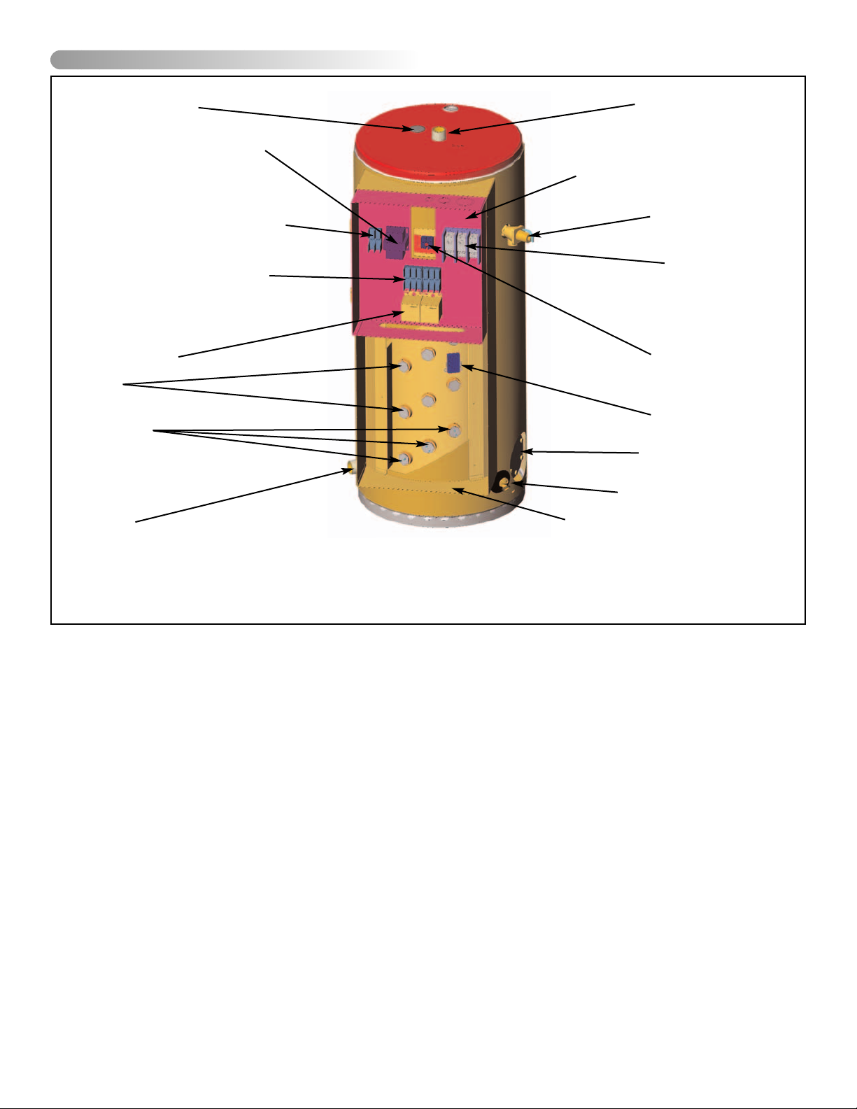
II) COMPONENT IDENTIFICATION
ANODE (UNDER
PLASTIC CAP)
POWER TRANSFORMER
(IF APPLICABLE)
FUSES (CONTROL CIRCUIT)
FUSES (POWER CIRCUIT)
(IF APPLICABLE)
CONTACTORS
PLUGS
HEATING
ELEMENTS
COLD
WATER
INLET
FIGURE 1: Parts Locations
HOT WATER
OUTLET
CONTROL COMPARTMENT
T&P VALVE
INPUT
TERMINAL
BLOCK
MANUAL
HIGH LIMIT
RESET
CONTROL
THERMOSTAT
CLEANOUT
DRAIN VALVE
ELEMENT COMPARTMENT
NOTES:
1. COVERS REMOVED FOR CLARITY.
2. 3 ELEMENT CONFIGURATION SHOWN.
3. COMPONENT LOCATION IN CONTROL COMPARTMENT
MAY VARY DEPENDING ON CONFIGURATION.
- 3 -
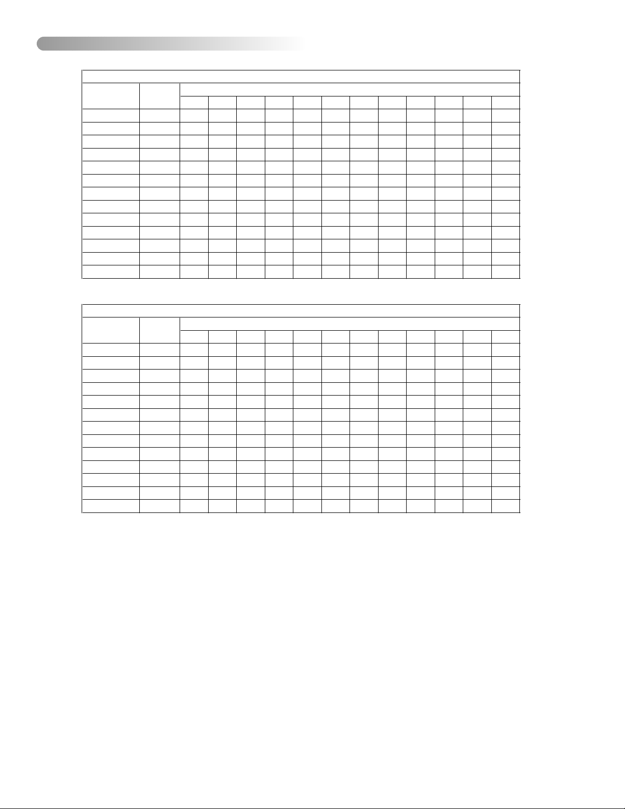
17° 22° 28° 33° 39° 44° 50° 56° 61° 67° 72° 78°
6 20,478 310 235 185 155 132 117 102 95 83 79 72 68
9 30,717 466 348 280 235 201 174 155 140 129 117 106 98
12 40,956 621 466 371 310 265 231 208 185 170 155 144 132
13.5 46,075 697 522 420 348 299 261 235 208 189 174 163 1518
15 51,195 776 583 466 386 333 291 257 231 212 193 178 167
18 61,434 931 697 560 466 397 348 310 280 254 231 216 201
24 81,912 1242 931 746 621 530 466 413 371 337 310 288 265
27 92,151 1397 1045 837 697 598 522 466 420 382 348 322 299
30 102,390 1552 1162 931 776 666 583 519 466 424 386 360 333
36 122,868 1862 1397 1117 931 799 697 621 560 507 466 428 397
40.5 138,226 2097 1582 1257 1049 897 787 700 628 572 522 485 450
45 153,585 2328 1745 1397 1162 996 871 776 697 636 583 538 500
54 184,302 2794 2093 1677 1397 1196 1049 931 837 761 697 644 598
30° 40° 50° 60° 70° 80° 90° 100° 110° 120° 130° 140°
6 20,478 82 62 49 41 35 31 27 25 22 21 19 18
9 30,717 123 92 74 62 53 46 41 37 34 31 28 26
12 40,956 164 123 98 82 70 61 55 49 45 41 38 35
13.5 46,075 184 138 111 92 79 69 62 55 50 46 43 401
15 51,195 205 154 123 102 88 77 68 61 56 51 47 44
18 61,434 246 184 148 123 105 92 82 74 67 61 57 53
24 81,912 328 246 197 164 140 123 109 98 89 82 76 70
27 92,151 369 276 221 184 158 138 123 111 101 92 85 79
30 102,390 410 307 246 205 176 154 137 123 112 102 95 88
36 122,868 492 369 295 246 211 184 164 148 134 123 113 105
40.5 138,226 554 418 332 277 237 208 185 166 151 138 128 119
45 153,585 615 461 369 307 263 230 205 184 168 154 142 132
54 184,302 738 553 443 369 316 277 246 221 201 184 170 158
RECOVERY RATE IN GALLONS PER HOUR
Standard
KW Input
BTU/Hr
Temperature rise in °F
RECOVERY RATE IN LITRES PER HOUR
Standard
KW Input
BTU/Hr
Temperature rise in °C
III) RECOVERY RATES
TABLE 1: Recovery Rates
- 4 -
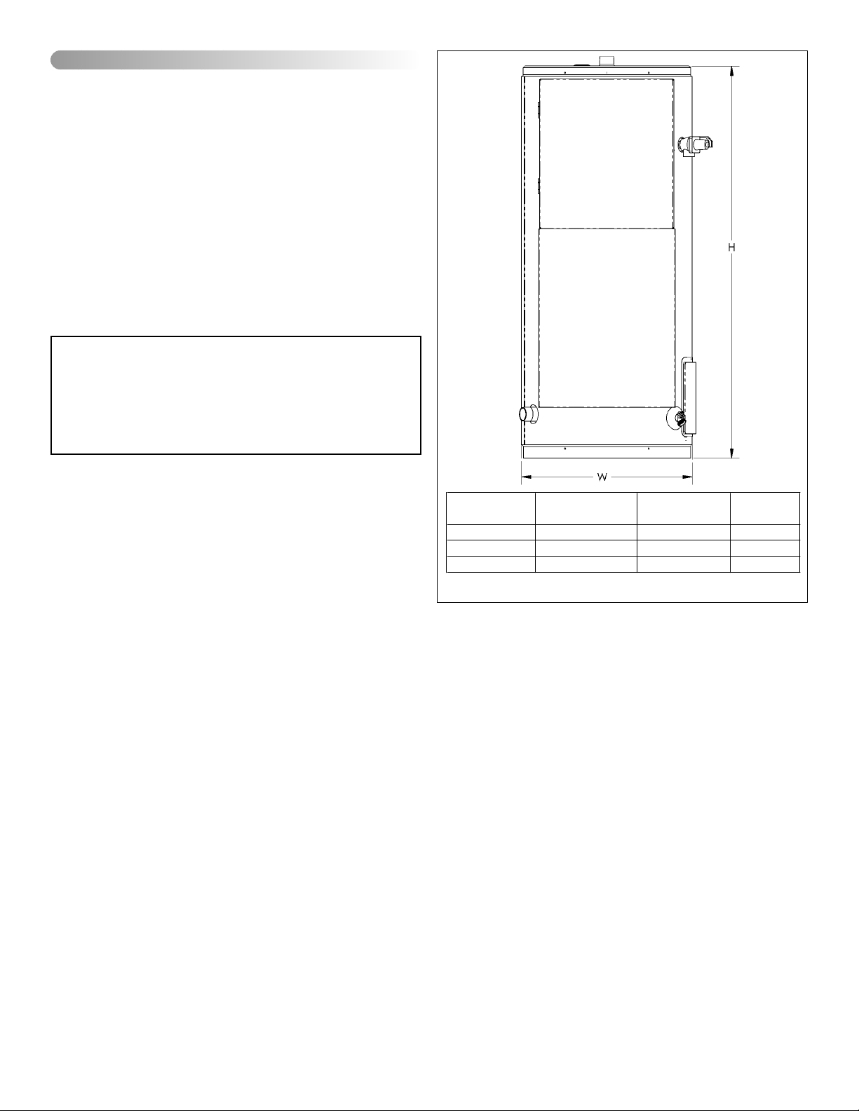
Capacity
(litres/USG)
Height
(meters/inches)
Width
(meters/inches)
Nipple Size
(inches)
184 / 50 1.31 / 51.5 0.57 / 22.25 1.5
280 / 80 1.56 / 61.5 0.62 / 24.25 1.5
420 / 119 1.65 / 64.75 0.73 / 28.5 1.5
IV) INSTALLATION
General
Applicable Codes
In addition to the installation instructions found in this manual, the water heater must be installed in accordance with
all local and provincial or state codes or, in the absence of
local and provincial or state codes, with the latest edition of
“Canadian Electrical Code” (in Canada) or NFPA-70
“National Electrical Code” (in USA).
The requirements of these documents must be carefully followed in all cases. Authorities having jurisdiction shall be
consulted before installations are made. Check your phone
listings for the local authorities having jurisdiction over your
installation.
Important: Installation and service must be performed by
a qualified service technician.
State of California
Note: The water heater must be braced,
anchored, or strapped to avoid moving during an earthquake. Contact local utilities for
code requirements in your area.
FAILURE TO FOLLOW THE INSTRUCTIONS IN
THIS MANUAL MAY RESULT IN DEATH, SERIOUS
BODILY INJURY AND/OR PROPERTY DAMAGE.
THOROUGHLY READ ALL INSTRUCTIONS
BEFORE YOU ATTEMPT TO INSTALL, OPERATE
OR MAINTAIN THIS HEATER.
Location Requirements
Refer to Figure 2 to determine the size of the various models of the water heater.
1. A clear space of 457mm (18 in.) should be allowed in
front of the heater to allow access to the controls and
elements.
2. A clearance of 305mm (12 in.) is sufficient clearance
from the top of the heater to adjacent surfaces.
3. It is suggested that the heater be located in the center of
the water system or close to the point-of-use requiring
the most hot water.
4. The water heater should be located in an area not subject to freezing temperatures.
5. Water heaters located in unconditioned spaces (i.e.,
attics, basements, etc.) may require insulation of the
water piping and drain piping to protect against freezing.
6. The drain and controls must be easily accessible for
operation and service.
This water heater is not intended for space heating
applications.
Temperature and Pressure (T&P) Relief
Valve
All water heaters must be installed with a proper temperature and pressure relief valve. In the United States this valve
must be design certified by a nationally recognized testing
laboratory that maintains periodic inspection of the produc-
FIGURE 2: Rough-in Dimensions
tion of listed equipment or materials as meeting the requirements for Relief Valves and Automatic Shut-off Devices for
Hot Water Supply Systems, ANSI Z21.22.
Important: Only a new temperature and pressure relief
valve should be used with your water heater. Do not use an
old or existing valve as it may be damaged or not adequate
for the working pressure of the new water heater. Do not
place any valve between the relief valve and the tank.
The T&P Valve:
• Must be connected to an adequate discharge line.
• Must not be rated higher than the working pressure
shown on the data plate of the water heater.
The Discharge Line:
• Must not be smaller than the pipe size of the relief valve
or have any reducing coupling installed in the discharge
line.
• Must not be capped, blocked, plugged or contain any
valve between the relief valve and the end of the discharge line.
• Must terminate a maximum of 152mm (6 in.) above a
floor drain or external to the building.
• Must be capable of withstanding 121°C (250°F) without
distortion.
- 5 -
• Must be installed to allow complete drainage of both the
valve and discharge line.
• Must not discharge so as to come in contact with any
electrical part or wiring.
Under no circumstances is the manufacturer to be held
responsible for any water damage in connection with
this water heater.
IMPORTANT:
This water heater must be installed strictly in accordance
with the instructions enclosed, and local electrical, fuel
and building codes. It is possible that connections to the
water heater, or the water heater itself, may develop
leaks. IT IS THEREFORE IMPERATIVE that the water
heater be installed so that any leakage of the tank or related water piping is directed to an adequate drain in such a
manner that it cannot damage the building, furniture, floor
covering, adjacent areas, lower floors of the structure or
other property subject to water damage. This is particularly important if the water heater is installed in a multi-story
building, on finished flooring or carpeted surfaces. GSW
WILL NOT ASSUME ANY LIABILITY for damage caused
by water leaking from the water heater, pressure relief
valve, or related fittings. Select a location as centralized
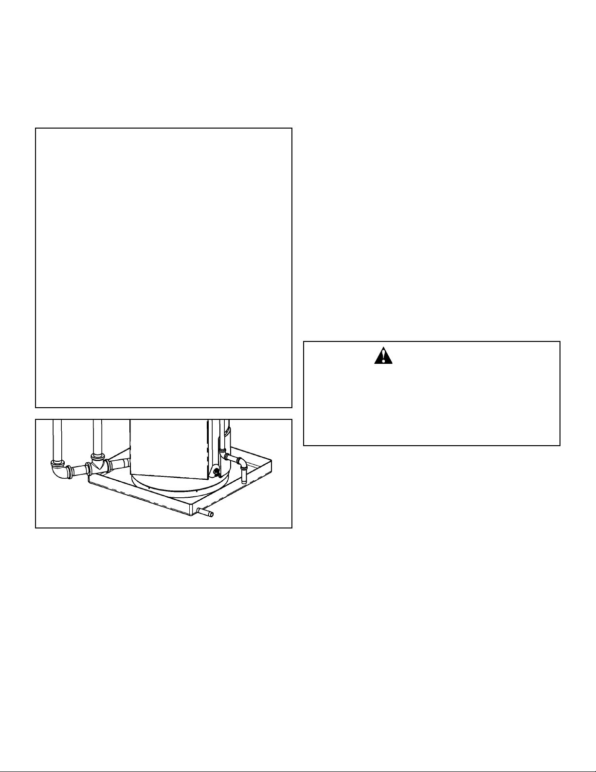
within the piping system as possible. In any location
selected, it is recommended that a suitable drain pan be
installed under the water heater. This pan must limit the
water level to a MAXIMUM depth of 45mm (1 3/4 in.) and
have a diameter that is a minimum of 50mm (2 in.) greater
than the diameter of the water heater. Suitable piping shall
connect the drain pan to a properly operating floor drain.
Closed System/Thermal Expansion
During the heating cycle of the water heater, the water
expands causing pressure inside the water heater to
increase. The water utility supply meter may contain a
check valve. This will create a closed water system. If the
pressure in a closed water system exceeds 1034kPa (150
PSI), water will discharge from the temperature and pressure (T&P) relief valve. This is the normal safety function of
a relief valve and indicates the proper functioning of the
valve. Only if the discharge from the relief valve is continuous or for an extended period of time does this indicate a
malfunction of some sort. Should this occur, have the operation of the heater checked by a technician qualified to do
so. Frequent operation of the T&P valve can result in a build
up of natural mineral deposits on the valve seat, rendering
the valve inoperative. Should this happen, the valve needs
to be replaced. To prevent this from happening install a
diaphragm-type expansion tank, that is suitable for potable
water, on the cold water supply line. The expansion tank
must have a minimum capacity of 6 litres (1.5 USG.) for
every 190 litres (50 USG) of stored water and be rated for
1034kPa (150 PSI) or the working pressure of the water
heater. NEVER PLUG OR REMOVE the T&P valve.
Important: Do not plug or remove the temperature
and pressure relief valve.
WARNING
Excessive Weight Hazard
Use two or more people to move and install
water heater.
Failure to do so can result in back or other
injury.
FIGURE 3: Drain Pan
WARNING!
Closets without drains and carpeted areas are examples of
unsuitable locations for any water heater. Select a location
as centralized within the piping system as possible. The
heater should be located in an area not subject to freezing
temperatures. If this heater is to be installed directly on carpeting, the carpeting must be protected by a metal or wood
panel beneath the heater, extending beyond the full width
and depth of the heater by a minimum 80mm (3 in.). If the
heater is installed in a closet or alcove, the entire floor must
be covered by the panel. This panel must be strong enough
to support the weight of the heater full of water without
breaking. Failure to heed this warning may result in a fire
hazard.
Unpacking the Water Heater
Important: Do not remove any permanent instructions,
labels, or the data label from the outside of the water heater
or on the inside of panels. Remove exterior packaging and
place installation components aside. Inspect all parts for
damage prior to installation and start-up. Completely read
and understand all instructions before attempting to assemble and install this product. After installation, dispose of
packaging material in the proper manner.
Important: Strictly follow the installation instructions
before making electrical connections.
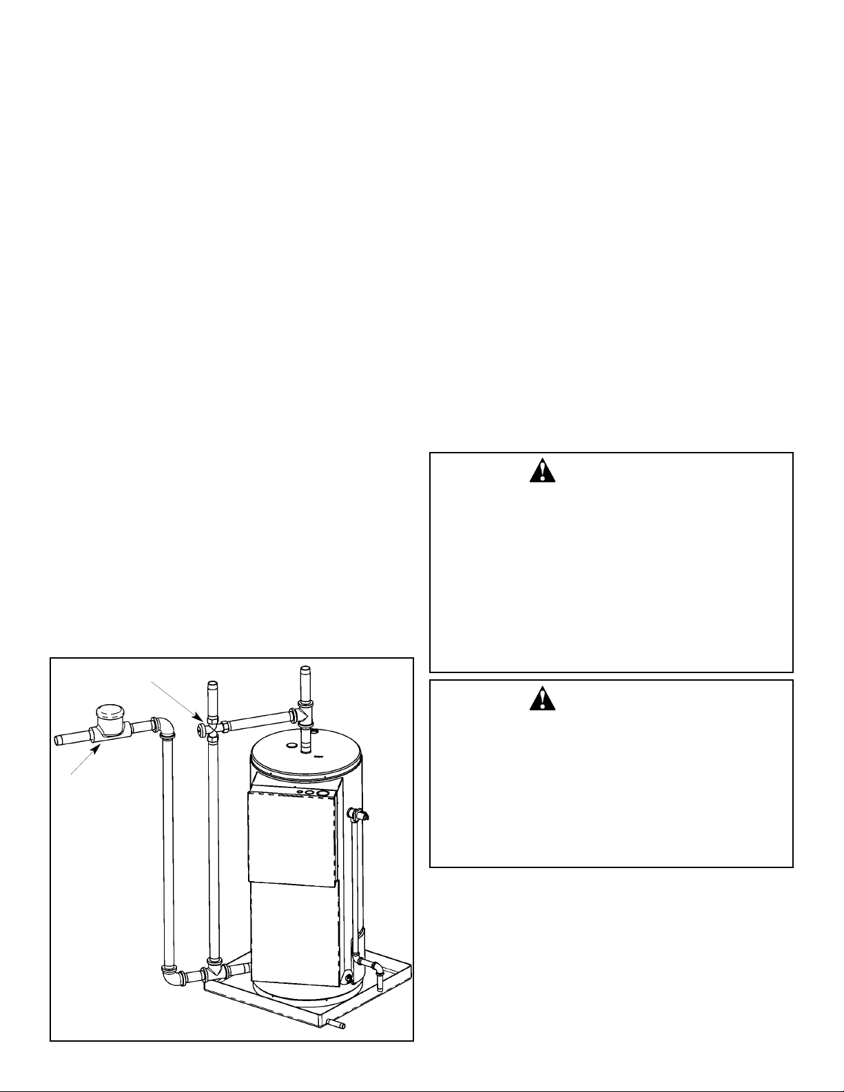
Piping Installation
Piping, fittings, and valves should be installed according to
the installation drawing (Figure 4). If the indoor installation
area is subject to freezing temperatures, the water piping
must be protected by insulation. Water supply pressure
should not exceed 80% of the working pressure stated on
the water heater’s data plate. If the supply pressure is higher than this limit, a pressure limiting valve with a bypass
must be installed in the cold water inlet line. This should be
placed on the supply to the entire building in order to maintain equal hot and cold water pressures.
- 6 -
Important: Heat must not be applied to the water fittings
on the heater as they may contain nonmetallic parts. If solder connections are used, solder the pipe to the adaptor
before attaching the adaptor to the hot and cold water fittings.
Important: Always use a good grade of joint compound
that is compatible with potable water and be certain that all
fittings are drawn up tight.
1. Install the water piping and fittings as shown in Figure 4.
Connect the cold water supply (1 1/2 in. NPT) to the fitting marked “Cold Water Inlet”. Connect the hot water
supply (1 1/2 in. NPT) to the fitting marked “Hot Water
Outlet”.
2. The installation of unions in both the hot and cold water
supply lines is recommended for ease of removing the
water heater for service or replacement.
3. The manufacturer of this water heater recommends
installing a tempering valve in the domestic hot water
line as shown in Figure 4. These valves reduce the pointof-use temperature of the water by mixing cold and hot
water and are readily available for use. Contact a
licensed plumber or the local plumbing supplier.
4. If installing the water heater in a closed water system,
install an expansion tank in the cold water line as specified under “Closed System/Thermal Expansion”.
5. Install a shut-off valve in the cold water inlet line. It
should be located close to the water heater and be easily accessible. Show the user the location of this valve
and how use it to shut off the water to the heater.
6. A temperature and pressure relief valve is installed in the
opening marked ”Temperature and Pressure (T&P)
Relief Valve” on the water heater. Add a discharge line to
the opening of the T&P relief valve. Follow the instructions under “Temperature and Pressure (T&P) Relief
Valve”.
7. After piping has been properly connected to the water
Tempering valve
heater, close the shut-off valve in the cold water inlet
line.
Please note the following:
DO NOT install this water heater with iron piping. The system should be installed only with piping that is suitable for
potable (drinkable) water such as copper, CPVC, or polybutylene. DO NOT use PVC water piping.
DO NOT use any pumps, valves, or fittings that are not
compatible with potable water.
DO NOT use valves that may cause excessive restriction to
water flow. Use full flow ball or gate valves only.
DO NOT use 50/50 tin-lead solder (or any lead based solder) in potable water lines. Use 95/5 tin-antimony or other
equivalent material.
DO NOT tamper with the temperature and pressure relief
valve. Tampering voids all warranties. Only qualified service
technicians should service these components.
DO NOT use with piping that has been treated with chromates, boiler seal, or other chemicals.
DO NOT add any chemicals to the system piping that will
contaminate the potable water supply.
DO NOT apply electrical power before the tank is filled with
water and you have confirmed that there are no leaks in the
piping and connections.
WARNING
TO REDUCE RISK OF ELECTRIC SHOCK OR POSSIBLE ELECTROCUTION THE WATER HEATER MUST
BE ELECTRICALLY GROUNDED. The electrical supply
to the water heater should be a separately grounded
branch circuit having overcurrent protection and a disconnect switch. Refer to the rating plate attached to the
heater to determine the correct ratings for voltage and
amperage. To ensure proper operation, the supply voltage
should be within +5% and -10% of the rated voltage of the
heater. The water heater should be grounded in accordance with national and local codes.
Water meter or
anti-siphoning
device
FIGURE 4: Piping Installation
WARNING
WATER HEATER EQUIPPED FOR LIMITED VOLTAGE
RANGE. This water heater is designed to operate within a
specific voltage range. Check rating plate mounted on the
heater for the correct voltage. DO NOT connect this water
heater to any voltage supply other than that indicated on
the rating plate. Failure to use the correct voltage may
result in unsafe operation and personal injury or property
damage. If you have any questions or doubts consult your
electric company.
Electrical Connections
CAUTION! TO PREVENT DAMAGE TO THE TANK AND
HEATING ELEMENT(S), THE TANK MUST BE FILLED
WITH WATER BEFORE TURNING "ON" POWER. SEE
"FILLING THE WATER HEATER".
The information in Table 3 may be used as a guide to determine the wire size of the branch circuit. It is recommended
the branch circuit wiring be 125% of the amperage rating of
- 7 -

the water heater. If the heater is located a long distance
away from the electrical supply, the wire size of the branch
circuit should be increased. The voltage measured at the
heater should not be less than 3% lower than what is measured at the supply. If your calculated value does not appear
in the table, substitute the next highest rating listed in the
table.
1. Ensure the element marking and rating plate data correspond with the electric service available.
2. Install a branch circuit directly from the main service
panel to the water heater. The wiring of this circuit must
be of adequate size for the length of run and the load
(see Table 3).
3. A ground wire must run from the green ground screw
provided at the electrical connection point in the heater
junction box to the ground connection at the service
panel.
4. Final connections are made in the control panel box on
the heater.
5. The heater you have received is internally wired. A specific wiring diagram for each heater is located inside the
control panel. All internal wiring is colour-coded and connections must be made as shown in the wiring diagrams
(Figures 5-10 for Canada, Figures 11-16 for USA).
Installation Check List
Check Here
1. Are the fuse and wire sizes correct?
2. Is the certified relief valve installed?
3. Were steps taken to prevent water damage in
case of leaks?
4. Has the relief valve been piped to a suitable
drain point?
5. Is the relief valve discharge unobstructed?
6. Is the heater completely filled with water?
7. Is the cold water supply valve open?
If the answer to the above are yes, turn on the
power and enjoy all the hot water you need, all the
time.
Fuses
Components in the power circuit are protected by fuses. For
voltage supplies up to 480V, the fuses are rated for 30
amperes, class G. For voltage supplies of 600V, the fuses
are rated for 15 amperes, class G. Replace fuses with same
size, type and rating only.
Note: These fuses are not required or installed in water
heaters sold in Canada.
Phase Conversion (USA only)
To Single Phase
If the heater is shipped for connection to a three-phase electrical service, it may be connected to a single-phase electrical service of the same voltage by making the following
changes:
1. Disconnect all the blue wires and all the yellow wires
from Terminal Block L3.
2. Reconnect all the blue wires to Terminal Block L1 (with
the black wires).
3. Reconnect all the yellow wires to Terminal Block L2 (with
the red wires).
4. Connect incoming power to Terminal Blocks L1 and L2.
To Three Phase
If the heater is shipped for connection to a single-phase
electrical service it may be connected to a three-phase electrical service of the same voltage by making these changes:
1. Disconnect all the blue wires from Terminal Block L1.
2. Disconnect all the yellow wires from Terminal Block L2.
3. Reconnect the blue wires and the yellow wires to
Terminal Block L3.
4. Connect incoming power to Terminal Blocks L1, L2, and
L3.
- 8 -
 Loading...