


GSW 70999 User Manual
GSW WATER HEATING
A GSW Company
599 Hill Street West
Fergus, ON, Canada N1M 2X1
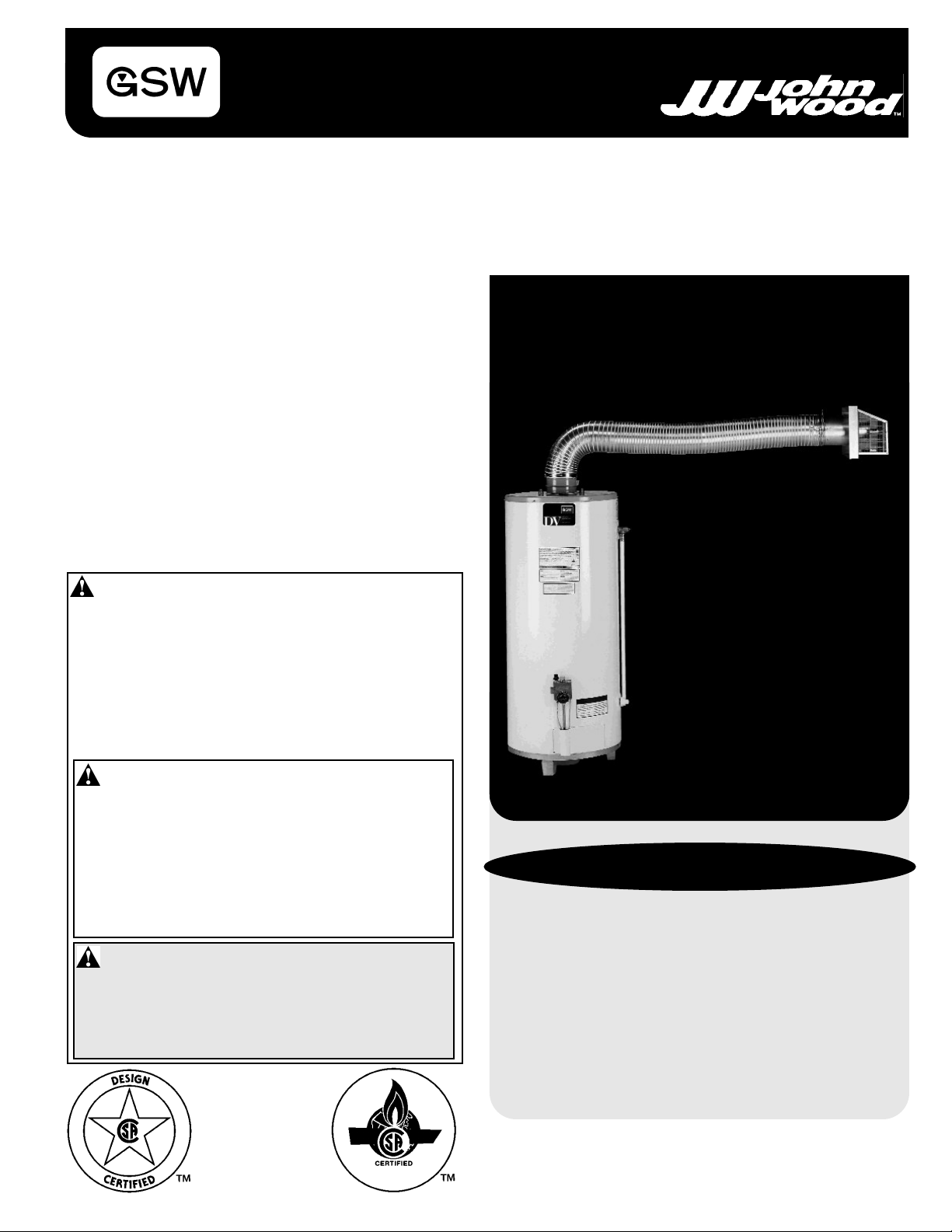
DIRECT VENT GAS FIRED WATER HEATER
INSTALLATION AND OPERATING INSTRUCTIONS
Read these instructions thoroughly before starting
TABLE OF CONTENTS
I) Installation & Location ............................................1
II) Replacement Parts Listing ....................................2
III) Vent Connections................................................3-5
IV) Gas Connections....................................................5
V) Water Pipe Connections ........................................5
VI) Temperature & Pressure ....................................5-6
VII) Lighting & Operating Instructions........................7-9
VIII) Service And Maintenance ....................................10
IX) Combo Heating ....................................................11
X) Warranty ..............................................................12
PLEASE RETAIN THESE INSTRUCTIONS IN A
SAFE LOCATION FOR FUTURE
FOR YOUR SAFETY
• Do not store or use gasoline or other
flammable vapours and liquids in the
vicinity of this or any other
appliance.
• Installation and service must be
performed by a qualified installer,
service agency or the gas supplier.
WARNING: Improper installation,
adjustment, alteration, service, or
maintenance can cause injury or
property damage. Refer to this
manual. For assistance or additional
information, consult a qualified
installer, service agency, or the gas
supplier.
WARNING: If the information in
these instructions is not followed
exactly, a fire or explosion may
result causing property damage,
personal injury or death.
WHAT TO DO IF YOU SMELL GAS?
• Do not try to light any appliance.
• Do not touch any electrical switch; do
not use any phone in your building.
• Immediately call your gas supplier
from a neighbor’s phone. Follow the
gas supplier’s instructions.
• If you cannot reach your gas supplier,
call the fire department.
PART NO. 70999 REV. G (03-12)
WARNING
This water heater must be installed strictly in
accordance with the detailed instructions
enclosed and local building codes. It must be
installed with a proper pressure relief valve
which may release water in operation. It is also
possible that connections to the water heater,
or the water heater itself, may develop leaks. It
is therefore IMPERATIVE that the water heater
be installed so that any water is directed to an
adequate drain in such a way that it cannot
damage the building, furniture, carpeting or
other property subject to water damage. GSW
CANNOT BE HELD RESPONSIBLE for
damage caused by water from the water
heater, pressure relief valve, or related fittings
where adequate provision to drain such water
has not been made. Closets without drains and
carpeted areas are examples of unsuitable
locations for any water heater.
These instructions have been written as a guide for the
proper installation and operation of your water heater.
The manufacturer will not be liable for any damages
caused by failure to comply with the installation and
operation instructions outlined in the following pages.
INSTALLATION
This heater must be installed by a qualified, licensed
gas fitter and according to CAN/CGA-B149 Installation
Code or ANSI Z223.1 National Fuel Gas Code and/or
local codes. If in doubt, consult your local utility.
The water heater should be located so that the controls
and drain are easily accessible. The heater should be
located in an area where leakage of tank or connections
will not result in damage to the area adjacent to the water
heater or to the lower floors of the structure. When such
locations cannot be provided, it is recommended that a
suitable drain pan be installed under the heater. Such
pans should be a maximum of 1 1/2 inches deep and
have a minimum length and width of at least 2 inches
greater than the diameter of the water heater and should
be piped to an adequate drain.
Under no circumstances is the manufacturer to be held
liable for any water damage in connection with this water
heater.
CAUTION: When this water heater is installed directly on
carpeting, carpeting must be protected by a metal or
wood panel beneath the appliance extending beyond the
full width and depth of the appliance by at least three
inches in any direction, or if the appliance is installed in
an alcove or closet, the entire floor must be covered by
the panel. The panel must be strong enough to carry the
weight of the heater when full of water. Failure to heed
this warning may result in a fire hazard.
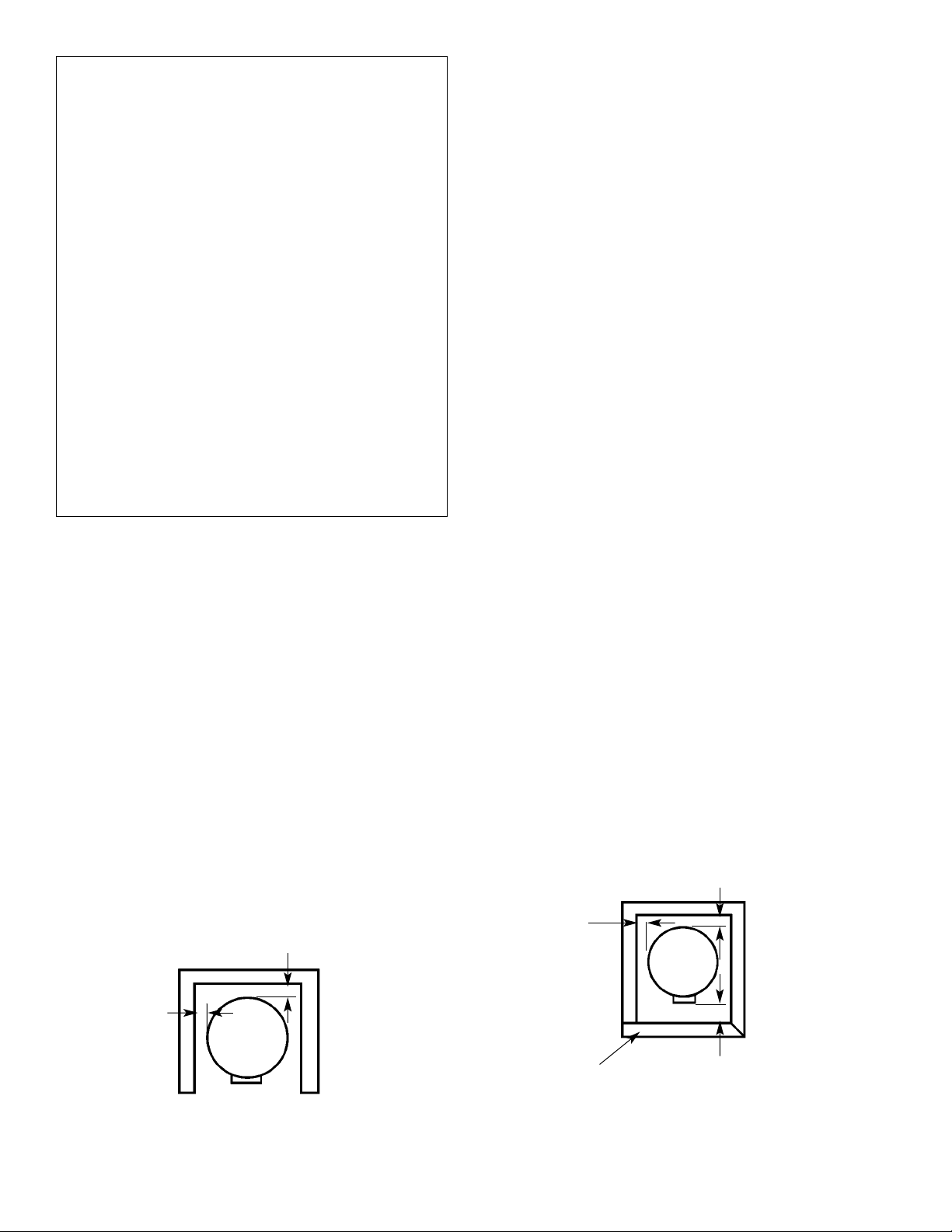
Minimum clearances between the heater and
combustible/non combustible materials are 1 inch at the
sides and rear; 20 inches from the top of water heater
and 1 inch around the vent pipe. A minimum of 3 feet of
clearance is required at the front (control) side of the
heater for service.
For a closet installation, the door at burner side should be
openable and a minimum of 4 inches clearance is
needed. Water heater is certified for installation on a
combustible floor. (See figure 1.)
LOCATION
Generally, the location selected should be as close to the
wall as practical and as centralized with the piping system
as possible. Heater should be located in an area not
subject to freezing temperatures.
1”
1”
ALCOVE INSTALLATION
– 1 –
1”
1”
CLOSET DOOR
CLOSET INSTALLATION (TOP VIEW)
4”
Figure 1
10
14
OPTION 2
13
OPTION 1
SEAL TIGHTLY
1
2
7
3
11
12
9
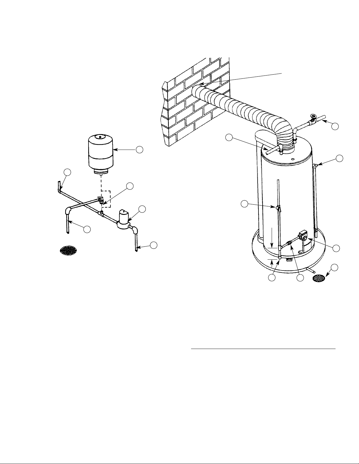
Location of pressure relief and/or expansion tank if a check
valve or pressure reducing valve is in the cold water supply to
the house.
Use OPTION 1 or 2 whichever is more convenient. If pressure
relief valve is used, select one with a setting 25 psi below valve
rating at tank.
6”
4
1. COLD WATER INLET
2. HOT WATER OUTLET
3. GAS SUPPLY MANUAL SHUT-OFF VALVE
4. SEDIMENT TRAP
5. UNION - GROUND JOINT TYPE
6. FLOOR DRAIN
7. TEMPERATURE & PRESSURE RELIEF VALVE
8. GAS CONTROL
9. WATER SUPPLY TO METER
10. WATER SUPPLY TO HOME
11. WATER METER WITH BACKFLOW PREVENTER
12. OVERFLOW
13. PRESSURE RELIEF VALVE
14. EXPANSION TANK
5
8
6
Figure 2
– 2 –
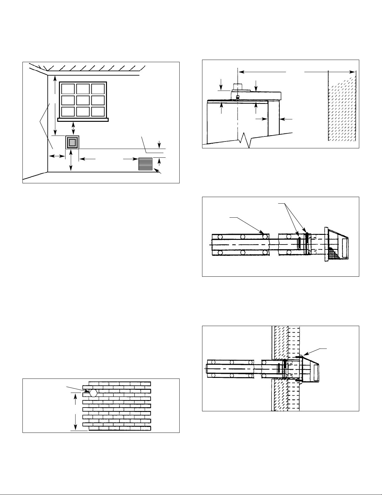
Specially For Direct Vent Water Heater:
Make certain to observe the vent location limitations
complying with the CAN/CGA-B149 Installation Code or
ANSI Z223.1 National Fuel Gas code and/or local codes.
There are some important issues shown in Figure 3.
recommended is 90” or in compliance with figure 3M.
*Where the wall is combustible and the wall thickness is
over 14”, 1 inch clearance to combustible materials around
the terminal pipe is needed. The first 14” is zero clearance.
Vent Terminal must be located at
least 12” from Windows, Doors,
or any other Opening through
18”
Min.
12” Min.
18”
Min.
Vent Terminal must be located at least 18”
from any overhang or building corner or
other irregularity.
12” Min. above grade. Higher
in Areas of Heavy Snowfall
which flue gases could enter the
building.
Vent terminal must be
located at least 36” above
any Forced Air Inlet into the
building within 10 feet of
the Vent Terminal
Within 10 feet
36”
Min.
Any Forced Air Inlet
into the building
Figure 3 - Vent Location Limitations
For a second or more direct vent unit, the distance
between vent terminals must have a minimum of 1 foot.
INSPECT SHIPMENT –– There may be hidden damage
caused by transit. Check to be certain all parts of the
venting system, as shown in Figures 3A through 3M, are
present. Inspect the upper and lower air inlet boxes, rear
air tube and all parts of the venting system.
CAUTION
If there are any damaged parts, DO NOT install this water
heater. Report any shortage to your distributor or damage
to your carrier.
Note: The four fasteners that are required to secure the
vent terminal to the exterior wall are not provided. These
should be screw type (not nails) chosen for the type of
construction and obtained locally.
CAUTION
Cut edges of corrugated (flex) pipe are extremely sharp.
Wear gloves when handling.
VENT CONNECTIONS - After the location for the vent
terminal has been selected as outlined in Figure 3, use
the following illustrations for installation:
MAX. 90”
4”
3”
4”
WALL
Figure 3 B - Moving Water Heater To Its Final
Installed Location.
Move the water heater to its final installed location. Make
certain clearances from combustible material are
observed. The maximum distance from center of water
heater to outside wall should not be longer than 90”.
CLAMP
SPRING
Figure 3 C - Vent Assembly.
The vent pipe and terminal are assembled by the
manufacturer as shown in figure 3C. There are springs
fastened inside the corrugated pipe. When the vent pipes
are pulled to a required length, the distances between the
springs will still be equally spaced.
SEALANT
7” DIAMETER
MIN.
68”
BOTTOM OF HEATER
Figure 3 A - Locating Clearance Hole for Vent.
Cut a clearance hole, approximately 7 inches in diameter,
through the exterior wall for the vent assembly. The
minimum height should not be less than 68” from the hole
center to bottom of water heater. The maximum height
Figure 3 D - Securing Vent Termination Assembly To
The Exterior Wall.
Introduce the 6” pipe through the clearance hole from
exterior wall then secure the vent terminal to the exterior
wall with 4 screw anchors appropriate for the type of
wall construction. Caulk the junction of the vent terminal
base plate and the exterior wall with exterior type
silicone sealant.
– 3 –