


GSW 319594-000 User Manual
PART NO. 319594-000 REV. 01 (10-11)
WARNING:
If the information in these instructions is
not followed exactly, a fire or explosion
may result causing property damage, personal injury or death.
WARNING:
Improper installation, adjustment, alteration, service, or maintenance can cause
injury or property damage. Refer to this
manual. For assistance or additional information, consult a qualified installer, service agency, or the gas utility.
FOR YOUR SAFETY
• Do not store or use gasoline or other
flammable vapours and liquids in the
vicinity of this or any other appliance.
• Installation and service must be performed by a qualified installer, service
agency or the gas utility.
• Do not try to light any appliance.
• Do not touch any electrical switch; do
not use any phone in your building.
• Immediately call your gas supplier from
a neighbor’s phone. Follow the gas
supplier’s instructions.
• If you cannot reach your gas supplier,
call the fire department.
WHAT TO DO IF YOU SMELL GAS
GSW Water Heating is a division of
A. O. Smith Enterprises Ltd.
POWER VENTED WATER HEATER
INSTALLATION AND
OPERATING INSTRUCTIONS
Read these instructions thoroughly before starting
– 2 –
TABLE OF CONTENTS
I) INTRODUCTION . . . . . . . . . . . . . . . . . . . . . . . . . . . 4
User Responsibilities 4
II) SAFETY. . . . . . . . . . . . . . . . . . . . . . . . . . . . . . . . . . 5
For Installations in Canada: 5
For Installations in the United States: 5
Safety Warning (Flammable Vapours) 5
Safety Warning (Scalding) 5
Safety Warning (Carbon Monoxide) 5
Relief Valve Requirements (T&P) 6
Flooding/Freezing 6
III) INSTALLATION. . . . . . . . . . . . . . . . . . . . . . . . . . . . 6
Unpacking the Water Heater 6
Location Requirements 6
In Earthquake Zones
Closet Installation & Floor Surfaces
Clearances and Accessibility 7
Gas Supply 7
Gas Supply Pressure
Gas line purging
Gas Leak Testing
Gas Operating Pressures
Air Requirements 9
Ventilated Space Air Requirements for Canadian
Installations 9
Ventilated Space Air Requirements for U.S.
Installations 10
Exhaust Venting 11
Important Notes and Warnings
Venting terminations and sizing
Venting instructions
Vent pipe connection to blower
Water Supply 15
Piping Installation
Filling the Water Heater
Closed System/Thermal Expansion
Temperature and Pressure (T&P) Relief Valve 16
The Temperature and Pressure Relief Valve:
The Discharge Line/Driptube:
Electrical Supply 17
Flammable Vapour Sensor 18
Resettable Lockout 19
Water Heater Operation 19
Installation Checklist 20
IV) OPERATING INSTRUCTIONS . . . . . . . . . . . . . . . 21
Temperature Regulation 21
Mixing Valves 21
Lighting Instructions (Robertshaw) 22
Gas Control/Thermostat
Putting the Heater into Service
Temperature Adjustment
Heater Shutdown
System Error Codes
Lighting Instructions (White-Rodgers) 24
Gas Control/Thermostat
Putting the Heater into Service
Temperature Adjustment
Heater Shutdown
System Error Codes
Intelli-Vent
TM
System Error Codes
V) OPERATION . . . . . . . . . . . . . . . . . . . . . . . . . . . . . 28
Burner Flames 28
Operational Conditions 28
Condensation
Water Heater Sounds
Smoke/Odour
Anode Rod/Water Odour
VI) MAINTENANCE . . . . . . . . . . . . . . . . . . . . . . . . . . 28
Draining and Flushing 28
Anode Rod Replacement 29
Routine Preventative Maintenance 29
Gas Control 29
Temperature and Pressure Relief Valve 29
Venting System and Blower 30
VII) COMBO HEATING . . . . . . . . . . . . . . . . . . . . . . . . 31
System Requirements 31
Installation 31
VIII) TROUBLESHOOTING GUIDE . . . . . . . . . . . . . . . 32
Robertshaw 2000WDER and
White-Rodgers Intelli-Vent
TM
32
IX) REFERENCE PARTS . . . . . . . . . . . . . . . . . . . . . . 33
Reference Parts Listing 33
Parts Reference Illustration 34
LIMITED WARRANTY. . . . . . . . . . . . . . . . . . . . . . 35
RETAIN THESE INSTRUCTIONS IN A SAFE LOCATION FOR FUTURE REFERENCE

– 3 –
This page intentionally left blank. May be used for notes or to record other installation information.
– 4 –
Your safety and the safety of others is very important.
We have provided many important safety messages in this manual and on your appliance.
Always read and obey all safety messages.
All safety messages will tell you what the potential hazard is, tell you how to reduce the
chance of injury, and tell you what can happen if the instructions are not followed.
This is the safety alert symbol.
This symbol alerts you to potential hazards that can kill or hurt you and others.
All safety messages will follow the safety alert symbol and either the word
“DANGER” or “WARNING”.
DANGER
WARNING
You can be killed or seriously injured if you don’t immediately follow
instructions.
You can be killed or seriously injured if you don’t follow instructions.
I) INTRODUCTION
Thank you for purchasing a Flammable Vapour Ignition
Resistant Power Vented Water Heater. This water heater
is designed to reduce the risk of flammable vapour related
fires by shutting the burner down before flammable vapours
get into the water heater combustion chamber. This is
achieved by the means of the flammable vapour sensor.
Properly installed and maintained, it will provide years of
trouble free service.
This gas-fired water heater has been developed to produce
potable hot water for normal residential demands and may
also be used in combination with space heating applications. Any deviation from these applications could affect
your warranty.
User Responsibilities
This manual has been prepared to acquaint you with the
installation, operation and maintenance of your gas fired
water heater and provide important safety information in
these areas. It is your responsibility to ensure that your
water heater is properly installed and cared for.
FAILURE TO FOLLOW THE INSTRUCTIONS IN THIS
MANUAL MAY RESULT IN SERIOUS BODILY INJURY
AND/OR PROPERTY DAMAGE. THOROUGHLY READ
AND UNDERSTAND ALL INSTRUCTIONS BEFORE YOU
ATTEMPT TO INSTALL, OPERATE OR MAINTAIN THIS
HEATER.
Installation and service requires trade knowledge in the
areas of plumbing, electricity, venting, air supply and gas
supply. If you lack these skills or have difficulty understanding these instructions, you should not proceed. Enlist the
help of a qualified service technician to install this water
heater.
Examples of qualified service technicians include those
trained in the plumbing and heating industry, local gas utility personnel or an authorized service person.
Service to the Power Vent System should only be performed by a qualified service technician.
The manufacturer and seller of this water heater will not
assume any liability for any property damage, personal
injury or death resulting from improper sizing, installation or
failure to comply with these instructions.
The warranty on this water heater is in effect only when the
water heater is installed and operated in accordance with
these instructions. Adata plate identifying your water heater
can be found above the gas control/thermostat. When referring to your water heater, always have the information listed
on the data plate readily available.
Protect your warranty: Regularly service your water
heater as directed in the "Maintenance" section of this manual.
Retain your original receipt as proof of purchase.
Do not discard this manual. You or future users of this
water heater will need it for reference.
II) SAFETY
This water heater is design-certified by CSAInternational as
a Category III, non-direct vented water heater that takes its
combustion air either from the installation area or from air
ducted to the unit from the outside.
In addition to the installation instructions found in this manual, the water heater must be installed in accordance with
all local and provincial or state codes or, in the absence of
such, with the latest editions of the following specifications.
For Installations in Canada:
"Natural Gas and Propane Installation Code" CAN/CSAB149.1 and "Canadian Electrical Code (CAN/CSA
C22.1), Part I" available from:
Canadian Standards Association,
5060 Spectrum Way,
Mississauga, Ontario, Canada
L4W 5N6
For Installations in the United States:
"National Fuel Gas Code" ANSI Z223.1 (NFPA 54) and
"National Electrical Code" (NFPA 70)" available from:
American National Standards Institute,
25 West 43rd Street,
New York, NY 10036
Massachusetts code requires this water heater to be
installed in accordance with Massachusetts Plumbing and
Fuel Gas Code 248 CMR Section 2.00 and 5.00.
Check your phone listings for the local authorities having
jurisdiction over your installation.
Safety Warning (Flammable Vapours)
There is a risk of property damage, personal injury or death
from the by-products of combustion (e.g., flue gases), in
using fuel-burning appliances such as water heaters. Areas
that may not be suitable for water heater installation include
those where flammable liquids, gasoline, solvents, adhesives etc. are stored, or where engine-driven equipment or
vehicles are stored, operated or repaired. These, and simi-
lar products, should not be stored or used near the water
heater or air intake. Due to the nature of air movement,
flammable vapours can be carried some distance from the
point of storage. The gas-fired water heater igniter or burner flame can ignite these vapours causing a flashback, fire
or explosion, which may result in severe property damage,
serious personal injury or death. If flammable liquids or
vapours have spilled or leaked in the area of the water
heater, leave the area immediately and call the fire department from a neighbor's home. Do not attempt to clean the
spill until all ignition sources have been extinguished.
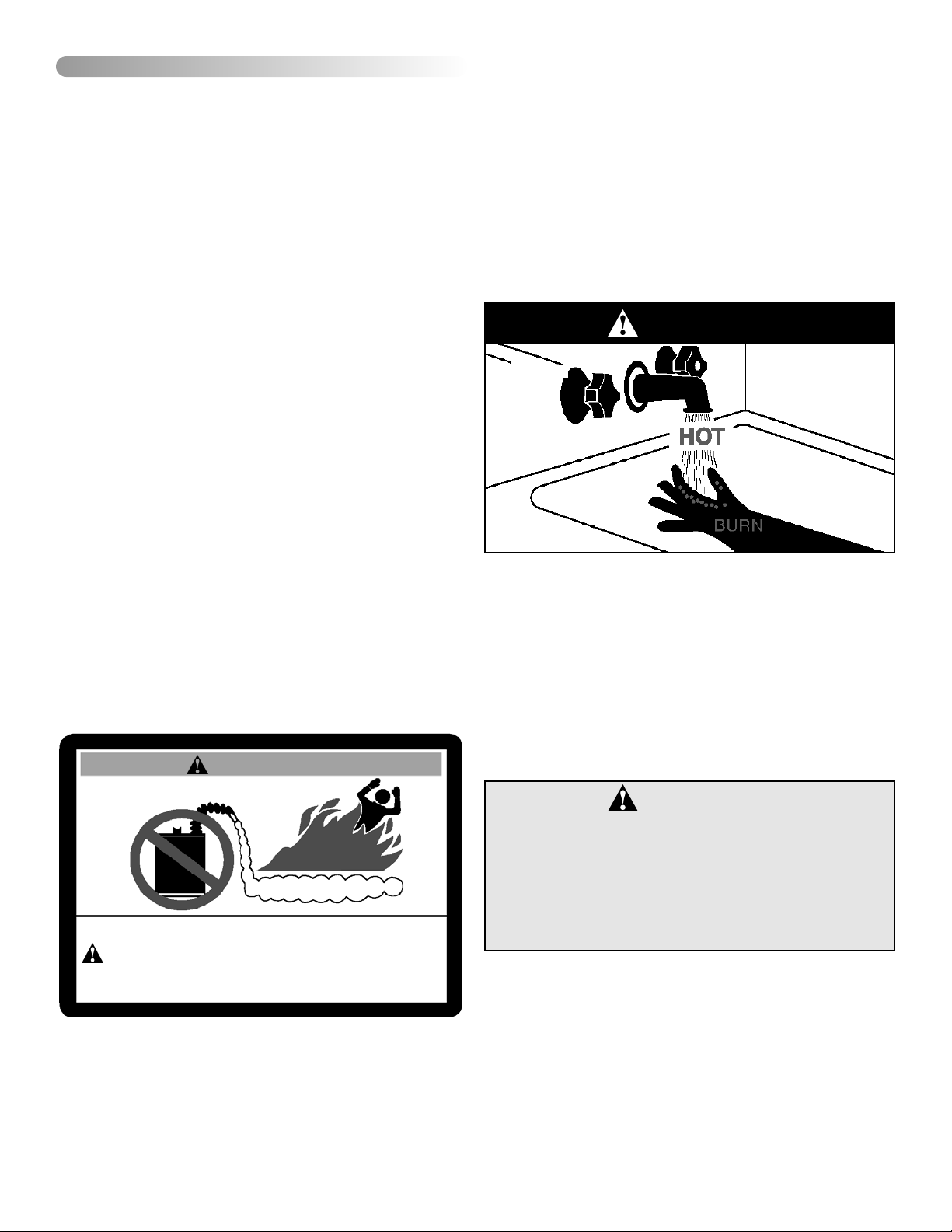
Safety Warning (Scalding)
Hot water produced by this appliance can cause severe
burns due to scalding. The hazard is increased for young
children, the aged or the disabled when water temperatures
exceed 52°C (125°F). Use tempering valves, also known as
mixing valves, in the hot-water system to reduce the risk of
scalding at point-of-use such as lavatories, sinks and
bathing facilities (see Figure 17). Such precautions must be
followed when this heater is operated in combination with
dishwashing or space heating applications.
Safety Warning (Carbon Monoxide)
As with all fuel burning equipment, this heater requires an
adequate supply of air for combustion and ventilation. An
insufficient air supply can result in poor combustion or the
re-circulation of the flue gases. Such a condition can cause
soot build-up and present a fire hazard. Flow reversal of flue
gases can cause an increase of carbon monoxide inside of
the dwelling that could result in serious bodily harm or death
from asphyxiation.
MAKE SURE THE FLOW OF COMBUSTION AND VENTILATION AIR IS NOT RESTRICTED.
WARNING
Flammable Vapours
FLAMMABLES
FIRE AND EXPLOSION HAZARD
Can result in serious injury or death
Do not store or use gasoline or other flammable vapours and liquids
in the vicinity of this or any other appliance. Storage of or use of gasoline
or other flammable vapours or liquids in the vicinity of this or any other
appliance can result in serious injury or death.
DANGER
DANGER
Carbon Monoxide Warning
• Follow all vent system requirements by
the local authorities having jurisdiction
over your installation.
• Failure to do so can result in death, explosion or carbon monoxide poisoning.
– 5 –
Relief Valve Requirements (T&P)
All water heaters must be fitted with a proper temperature
and pressure relief valve. These valves must be certified as
meeting the requirements of the "Standard For Relief
Valves For Hot Water Supply Systems, ANSI
Z21.22/CSA 4.4".
Flooding/Freezing
If this water heater has been exposed to flooding, freezing,
fire or any unusual condition, do not put it into operation until
it has been inspected and approved by a qualified service
technician. THESE CONDITIONS CAN RESULT IN
UNSEEN INTERNAL DAMAGE and are not subject to warranty coverage.
III) INSTALLATION
Unpacking the Water Heater
Important: Do not remove any permanent instructions,
labels, or the data label from outside of the water heater or
on the inside of panels.
• Remove exterior packaging and place installation components aside.
• Inspect all parts for damage prior to installation and
start-up.
• Completely read all instructions before attempting to
assemble and install this product.
If you observe damage to the water heater or any of its components, DO NOT ASSEMBLE OR INSTALL IT OR MAKE
ANY ATTEMPT TO FIX THE DAMAGED PART(S). Contact
the place of purchase for further instructions.
• After installation, dispose of packaging material in the
proper manner.
Location Requirements
The water heater must be installed indoors in an area not
subject to freezing temperatures and in a vertical position
on a level surface. Water heaters located in unconditioned
spaces (e.g., attics, basements etc.) may require insulation
of the water piping, drain piping and venting to protect
against condensation. The power vented series of water
heaters are designed to vent the products of combustion
horizontally through the wall or vertically through the roof.
The blower expels the products of combustion by means of
plastic piping to the outdoors without the need for a conventional chimney.
Select a location as centralized within the piping system as
possible. The heater should be located in an area where
leakage of the tank or connections will not result in damage
IMPORTANT:
This water heater must be installed strictly in accordance
with the instructions enclosed, and local electrical, fuel
and building codes. It is possible that plumbing connections to the water heater, or the water heater itself, may
develop leaks. IT IS THEREFORE IMPERATIVE that the
water heater be installed so that any leakage of the tank
or related water piping is directed to an adequate drain in
such a manner that it cannot damage the building, furniture, floor covering, adjacent areas, lower floors of the
structure or other property subject to water damage. This
is particularly important if the water heater is installed in a
multi-story building, on finished flooring or carpeted surfaces. GSW WILL NOT ASSUME ANY LIABILITY for
damage caused by water leaking from the water heater,
pressure relief valve, or related fittings. Select a location
as centralized within the piping system as possible. In any
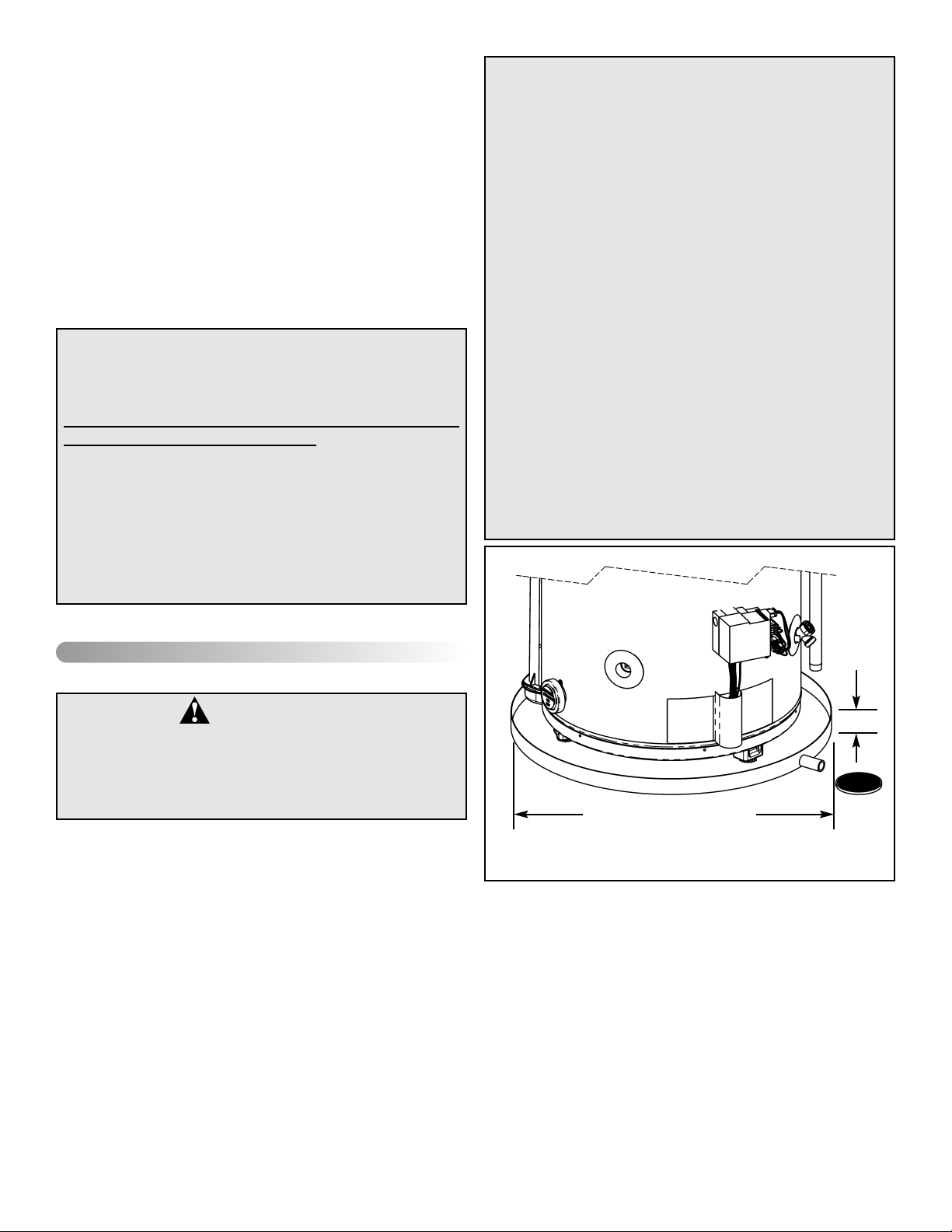
location selected, it is recommended that a suitable drain
pan be installed under the water heater. This pan must
limit the water level to a MAXIMUM depth of 45mm (1 3/4
in.) and have a diameter that is a minimum of 50mm (2 in.)
greater than the diameter of the water heater. Suitable
piping shall connect the drain pan to a properly operating
floor drain. When used with a fuel-fired heater, this drain
pan must not restrict combustion air flow.
WARNING
Excessive Weight Hazard
Use two or more people to move and install
water heater. Failure to do so can result in
back or other injury.
CAUTION
Hydrogen gas can be produced in a hot water system
served by this heater that has not been used for a long
period of time (generally two (2) weeks or more).
Hydrogen gas is extremely flammable and can ignite
when exposed to a spark or flame. To reduce the risk of
injury under these conditions, it is recommended that the
hot water faucet be opened for several minutes at the
kitchen sink before using any electrical appliance connected to the hot water system. Use caution in opening
faucets. If hydrogen is present, there will probably be an
unusual sound such as air escaping through the pipe as
the water begins to flow. There should be no smoking or
open flame near the faucet at the time it is open.
45mm MAX
(1 3/4 in.)
AT LEAST 50mm (2 in.)
GREATER THAN THE DIAMETER
OF THE WATER HEATER.
PIPE TO
ADEQUATE
DRAIN
Figure 1 Drain Pan Installation
– 6 –
– 7 –
to the area adjacent to the water heater or to lower floors of
the structure (see "IMPORTANT" notice on the previous
page). Before installing this water heater, consideration and
planning must be given to the following details:
• Proximity to walls and other objects (see "Clearance
and Accessibility").
• Access to gas supply (see "Gas Supply").
• Routing and support of the vent piping and termination
(see "Venting").
• Position of water supply and placement of water piping
and floor drain (see "Water Supply").
In Earthquake Zones
The water heater must be braced, anchored, or strapped to
avoid moving during an earthquake. Contact local utilities
for code requirements in your area.
Closet Installation & Floor Surfaces
The water heater may be installed in a closet with a door off
a bedroom or bathroom providing the units are installed and
vented per the manufacturer's instructions.
Important: If installing over carpeting, the carpeting must
be protected by a metal or wood panel beneath the water
heater. The protective panel must extend beyond the full
width and depth of the water heater by at least 76mm (3 in.)
in each direction or if in an alcove or closet installation, the
entire floor must be covered by the panel.
Clearances and Accessibility
• The minimum clearances between the heater and com-
bustible materials are:
Top 200mm (8 in.)
Front 100mm (4 in.)
Rear and Sides 25mm (1 in.)
Note: These requirements are also listed on the data plate
located on the front of the water heater.
• The water heater is certified for installation on a com-
bustible floor.
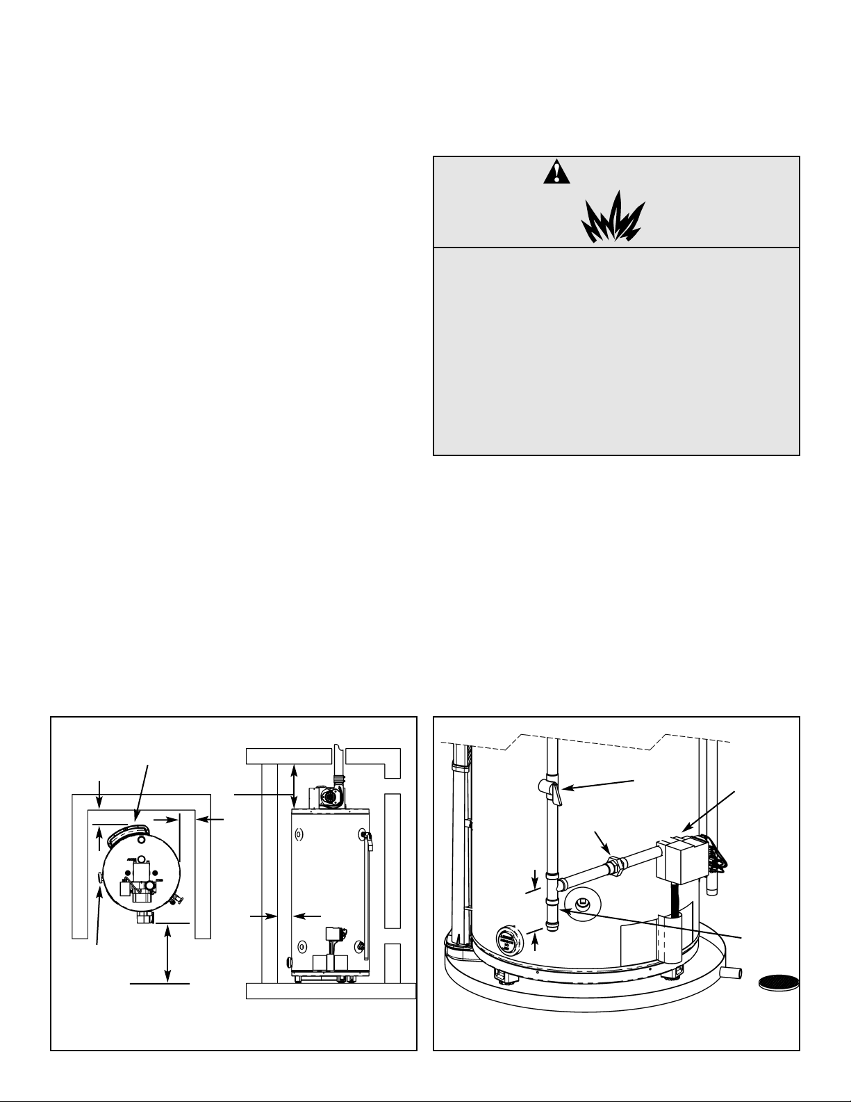
Figure 2 may be used as a reference guide to locate the
specific clearance locations. A minimum of 600mm (24 in.)
of front and top clearance and 100mm (4 in.) on each side
should be provided for inspection and service.
Gas Supply
Read the data plate to be sure the water heater is made
for the type of gas you will be using in your home. This
information will be found on the data plate located above the
gas control valve. If the information does not agree with the
type of gas available, do not install or attempt to start. Call
your dealer.
Note: An odourant is added by the gas supplier to the gas
used by this water heater. This odourant may fade over an
extended period of time. Do not depend upon this odourant
as an indication of leaking gas.
FRONT 600mm
(24 in.) MIN.
FOR SERVICE
BACK
AIR INTAKE *
SENSOR *
SIDES
SIDES
VENT
VENT
TOP TO
CEILING
* DO NOT BLOCK AIR INTAKE OR SENSOR ACCESS. ENSURE ADEQUATE
CLEARANCE FOR AIR SUPPLY
Figure 2 Minimum Clearance Locations
DANGER
Explosion Hazard
• Use a CSA approved gas supply line.
• Install a gas supply shut-off valve.
• Do not connect a natural gas water heater
to a L.P. gas supply.
• Do not connect a L.P. gas water heater to
a natural gas supply
• Failure to follow these instructions can
result in death, an explosion or carbon
monoxide poisoning.
Figure 3 Gas Piping (typical)
DRIP LEG
MANUAL
GAS
SHUT-OFF
GAS
CONTROL/
THERMOSTAT
76mm
(3 in.)
GROUND-
JOINT UNION
ALCOVES
CLOSETS

This gas piping must be installed in accordance with all local
and provincial or state codes or , in the absence of such, the
latest edition of "Natural Gas and Propane Installation
Code" CAN/CSA-B149.1 (Canada), or "National Fuel Gas
Code" ANSI Z223.1 (NFPA 54) (U.S.A.).
Use properly sized gas piping to ensure full gas input and a
properly sized gas supply regulator to ensure adequate gas
supply pressure. The supply piping and regulator must be
large enough to satisfy the requirements of all appliances
connected to the gas service when all appliances are operating simultaneously. Undersized piping and insufficient
pressure can restrict the gas flow causing the water heater
to perform poorly. Improperly sized piping may pose a safety hazard.
Note: When installing gas piping, apply sealing compounds
approved for use with natural and propane gas.
1. Install a readily accessible manual shut-off valve in the
gas supply line as recommended by the local utility . The
owner/operator must be shown the location of this valve
and be given instructions on how to use it to shut off the
gas to the heater.
2. Install a drip leg (if not already incorporated as part of
the water heater) as shown. The drip leg must be no
less than 76mm (3 in.) long for the accumulation of dirt,
foreign material, and water droplets.
3. Install a ground joint union, or other approved gas disconnect, between the gas control/thermostat and the
manual shut-off valve. This is to allow easy removal of
the gas control/thermostat.
4. Turn the gas supply on and check for leaks. Use a chloride-free soap and water solution (bubbles forming indicate a leak) or other approved method.
Gas Supply Pressure
Important: The gas supply pressure must not exceed the
maximum supply pressure as stated on the water heater's
data plate.
Gas line purging
Air may be present in the gas lines and could prevent the
burner from lighting on initial start-up. The gas lines should
be purged of air by a qualified service technician after installation of the gas piping system.
Gas Leak Testing
Important: This water heater and its gas connection must
be leak tested before placing the appliance in operation.
• If the code requires the gas lines to be tested at a pressure exceeding 14 in. w.c. (3.5 kPa), the water heater
and its manual shut-off valve must be disconnected
from the gas supply piping system and the line capped.
• If the gas lines are to be tested at a pressure less than
14 in. w.c. (3.5 kPa), the water heater must be isolated
from the gas supply piping system by closing its manual shut-off valve.
Gas Operating Pressures
The gas supply pressure and burner manifold pressure is
listed on the data plate located on the front of the heater
above the gas control/thermostat. Ensure the gas supply
pressure to the water heater and the burner manifold pressure are properly adjusted while all appliances are in operation. Refer to Figure 22 (Robertshaw) or Figure 24 (WhiteRodgers) for Gas Control/Thermostat Details.
U.L.and CSA recognized fuel gas and Carbon Monoxide
(CO) detectors are recommended in all applications and
should be installed using the manufacturer's instructions
and local codes, rules or regulations.
WARNING
Exposure to a higher gas supply pressure
may cause damage to the control, resulting
in explosion or fire. Consult your local gas
supplier and gas authorities. DO NOT PUT
INTO SERVICE IF OVER-PRESSURIZATION
HAS OCCURRED.
– 8 –
Air Requirements
Important: Air for combustion and ventilation must not
come from a corrosive atmosphere. Any failure due to corrosive elements in the atmosphere is excluded from warranty coverage.
Installations in or for certain places including, but not limited
to, those listed below may require outdoor air for combustion to reduce the risk of chemical exposure:
• Beauty shops, Photo processing labs
• Buildings with indoor pools
• Water heaters installed in laundry, hobby or craft rooms
• Water heaters installed near chemical storage areas
In such circumstances, outdoor combustion air may reduce,
but will not eliminate the presence of corrosive chemicals in
the air. Combustion air must be free of acid-forming chemicals such as sulfur, fluorine and chlorine. These elements
are found in aerosol sprays, detergents, bleaches, cleaning
solvents, air fresheners, paint and varnish removers, refrigerants and many other commercial and household products. When burned, vapours from these products form highly corrosive acid compounds. These products should not be
stored or used near the water heater or air inlet.
The area in which the heater is located is classified as either
"an unconfined sp
ace" or "a ventilated space."
An unconfined space
is defined as a space having a volume not less than 50 cubic feet per 1000 BTU/hour (4.8
cubic metres per kilowatt) of combined input rating of all
appliances using the space. Adjacent open rooms may be
included as part of the unconfined space, provided there
are no closeable doors between these rooms. An example of this is an open basement.
A ventilated sp
ace is one smaller than described above.
For buildings using tight construction (newer and renovated
structures), the air supply shall be introduced from the outdoors, regardless of whether the space is confined or
unconfined. CHECK LOCAL CODES.
Ventilated Space Air Requirements for
Canadian Installations
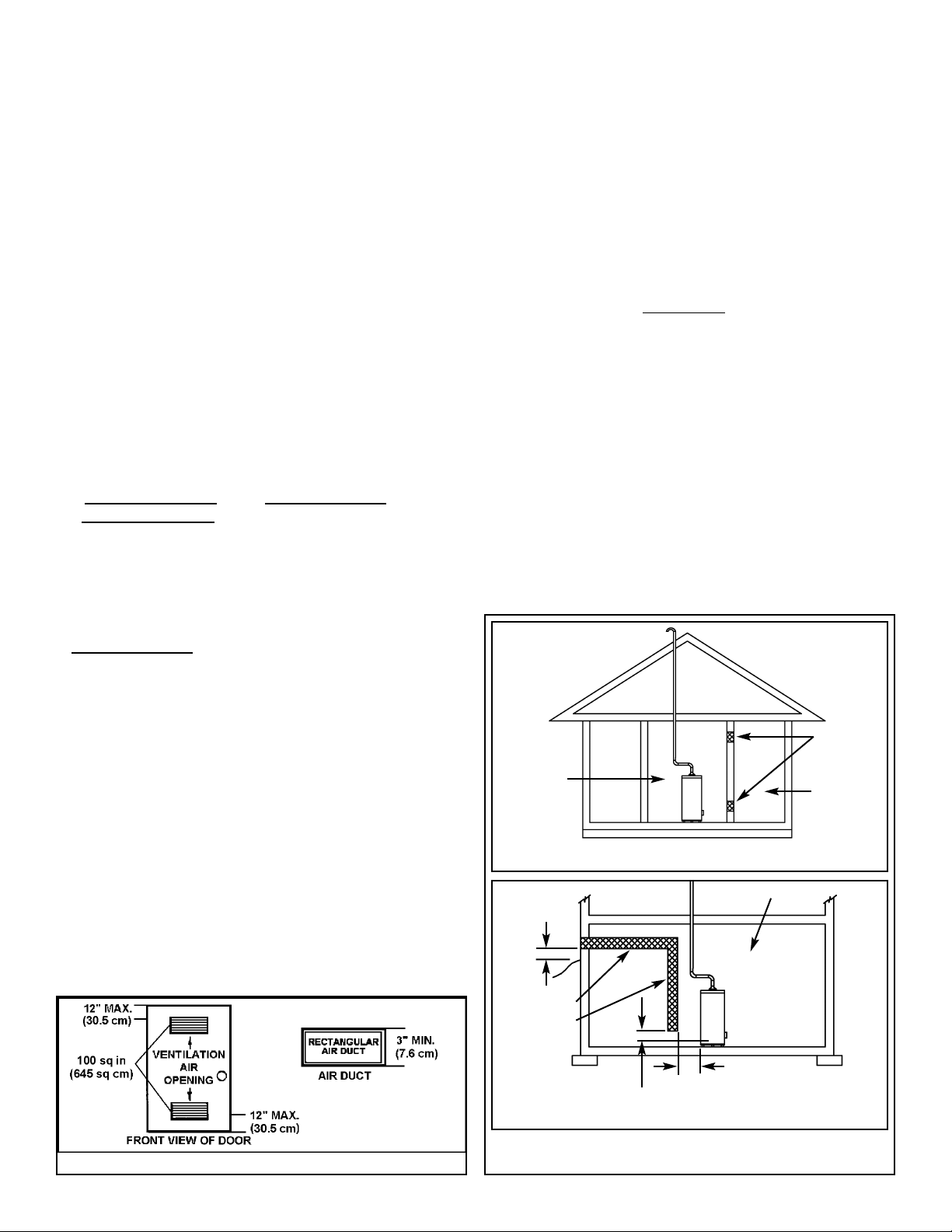
Refer to Figure 4 (a), or (b), for proper sizing and location of
combustion air ducts and openings. CHECK LOCAL
CODES.
a). Two permanent openings shall be provided connecting
to ventilated space (e.g. closet, small room) with the
unconfined space. Each opening shall be equal or
greater than 645cm
2
(100 in2.) with a width to height
ratio of 2:1. The top opening shall be located close to
the ceiling.
Note: The top opening shall not be lower than the top of the
heater. The location of the bottom opening shall be 150450mm (6-18 in.) above floor level.
Note: Ensure sufficient ventilation air to prevent elevated temperatures in closets and ventilated spaces.
When an exhaust fan is installed in the same room as the
water heater, the supply air openings must be of sufficient
capacity to prevent a backflow of air through the water
heater exhaust venting.
b). When using a single air supply, the duct shall terminate
within 300mm (12 in.) above and within 600mm (24 in.)
horizontally of the burner level
of the appliance having
the largest input.
Refer to latest edition of the "Natural Gas and Propane
Installation Codes" CAN/CSA-B149-1 for air supply duct
sizes.
– 9 –
Figure 4a Air Opening Locations
VENTILATED
SPACE
PERMANENT
OPENINGS
EQUIPMENT LOCATED IN VENTILATED
SPACES; ALL AIR FROM INSIDE THE BUILDING.
(a)
UNCONFINED
SPACE
BASEMENT INSTALLATION, EQUIPMENT LOCATED
IN VENTILATED SPACES; ALLAIR FROM OUTDOORS
(b)
VENTILATED
SPACE
GRADE
COMBINATION
COMBUSTION/
VENTILATION
AIR DUCT
300mm
(12 in.)
(MIN)
300mm (12 in.)
600mm (24 in.)
Figure 4 Combustion Air Supply Openings And Ducts
(Can.)
Ventilated Space Air Requirements for
U.S. Installations
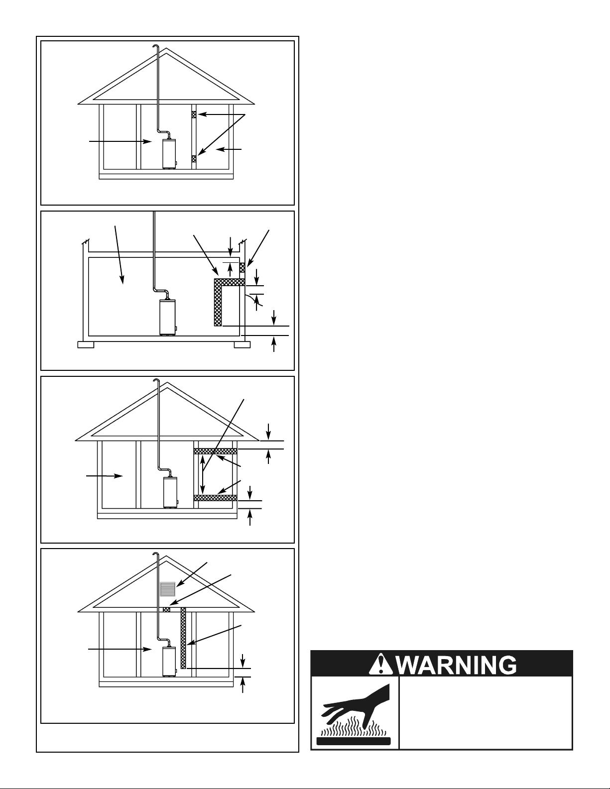
Refer to Figure 5 (a), (b), (c) or (d) for proper sizing and
location of combustion air ducts and openings. CHECK
LOCAL CODES.
a) Equipment located in ventilated spaces; all air from
inside the building.
Two permanent openings shall be provided connecting
to ventilated space (e.g. closet, small room) with the
unconfined space. Each opening shall be equal or
greater than 645cm
2
(100 in2.) with a width to height
ratio of 2:1. The top opening shall be located close to
the ceiling.
Note: The opening shall not be lower than the top of the
heater. The location of the bottom opening shall be 150450mm (6-18 in.) above floor level.
b) Basement installation, equipment located in ventilated
spaces; all air from outdoors.
Refer to the latest edition of the "National Fuel Gas
Code" ANSI Z223.1 for air supply duct sizes and
restrictions.
c) Equipment located in ventilated spaces; all air from out-
doors.
Refer to the latest edition of the "National Fuel Gas
Code" ANSI Z223.1 for air supply duct sizes and
restrictions.
d) Equipment located in ventilated spaces; all air from out-
doors through ventilated attic.
Refer to the latest edition of the "National Fuel Gas
Code" ANSI Z223.1 for air supply duct sizes and
restrictions.
Note: Ensure sufficient ventilation air to prevent elevated temperatures in closets and ventilated spaces.
When an exhaust fan is installed in the same room as the
water heater, the supply air openings must be of sufficient
capacity to prevent a backflow of air through the water
heater exhaust venting.
Burn Hazard
Do not touch vent.
Doing so can result in
burns.
– 10 –
VENTILATED
SPACE
PERMANENT
OPENINGS
EQUIPMENT LOCATED IN VENTILATED
SPACES; ALL AIR FROM INSIDE THE BUILDING.
(a)
UNCONFINED
SPACE
VENTILATED
SPACE
ATTIC LOUVERS TO OUTDOORS
EQUIPMENT LOCATED IN VENTILATED SPACES; ALL
AIR FROM OUTDOORS THROUGH VENTILATED ATTIC.
(d)
INLET AIR
DUCT
OUTLET
AIR
BASEMENT INSTALLATION, EQUIPMENT LOCATED
IN VENTILATED SPACES; ALLAIR FROM OUTDOORS
(b)
VENTILATED
SPACE
GRADE
300mm
(12 in.)
300mm
(12 in.)
Figure 5 Combustion Air Supply Openings And Ducts
(U.S.A.)
COMBUSTION
AIR DUCT
PERMANENT
VENTILATION
AIR.
300mm
(12 in.)
ABOVE
GRADE
OR
SNOW
LINE
EQUIPMENT LOCATED IN VENTILATED
SPACES; ALL AIR FROM OUTDOORS.
(c)
VENTILATED
SPACE
COMBUSTION
300mm (12 in.)
300mm (12 in.)
300mm (12 in.)
OUTDOORS
AIR DUCT
VENTILATION
Exhaust Venting
This heater is designed to exhaust the products of combustion (flue gases) to the outdoors using a sealed piping system. Table 2 lists the allowable vent materials and sizing
information. Figure 8 shows the general venting layout while
Figures 9-11 show various end termination details and
clearances. Connection of the venting piping to the blower
is shown in Figures 13-15.
Correct installation of the venting system is essential to the
safe and efficient operation of this water heater. Vent piping
must be installed in accordance with all applicable local and
provincial or state codes. In the absence of such codes, all
installation shall meet the requirements as stated in the latest edition of the "Natural Gas and Propane Installation
Codes" CAN/CSA-B149-1 (Canada) or "National Fuel
Gas Code" ANSI Z223.1 (NFPA 54) (U.S.A.).
Note: The information provided in Figure 6 is intended as a
guideline for good vent installation practices only and is not
intended to restrict venting options beyond those restrictions established by the latest edition of the "Natural Gas
and Propane Installation Codes" CAN/CSA-B149-1 or
any applicable local and provincial codes.
Important Notes and Warnings
• This heater is certified to be installed using Schedule 40
PVC or CPVC plastic vent material. In Canada some
jurisdictions require that this material is approved to
ULC S636. ULC S636 mandates that components from
different systems must not be mixed in the same vent
runs. Check local codes to determine which materials
are allowed in your area and only use approved material. All venting material and components must be joined
with the approved primer/cleaner and solvent cement.
• Do not common vent this heater with any other appliance.
• During operation the plastic piping will expand as it
heats up and contract as it cools down. This is normal
for this type of venting. Rigidly fastening the vent piping
can cause undue stress that may result in the cracking
or fracturing the vent piping material. A fracture of the
venting pipe poses a serious safety hazard. To prevent
stressing of the vent system, all hangers and supports
must allow the vent piping freedom to move.
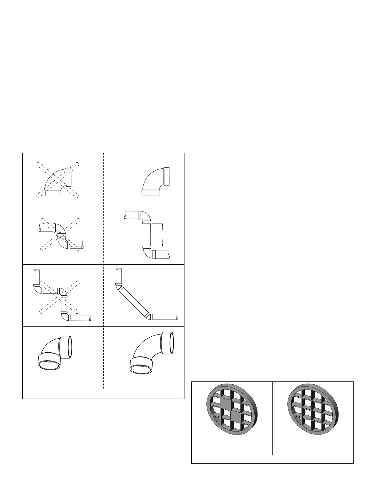
• Use long sweep elbows wherever possible. Closelycoupled elbows and short radius elbows can reduce the
venting capacity.
• All power vented water heaters generate a certain
amount of operational noise. In order to minimize noise
transmission to the support structure, use isolation pads
between the pipe hangers and the vent pipe.
• Most power vent installations develop some condensation in the vent piping. When using long runs of venting
or when the venting passes through cold or unheated
areas, considerable amounts of condensate from the
flue gases can develop. Provision must be made for the
condensate to drain freely from the system or to be collected in a condensate trap(s) that can be drained.
Damage or fracture of the vent piping may occur if the
condensate is allowed to collect and freeze. Pooling of
condensate can restrict airflow and can cause nuisance
failures of the system.
• Be aware of any concealed wiring or piping inside the
walls.
• Ensure sufficient ventilation air to prevent elevated temperatures in closets and ventilated spaces.
– 11 –
VENT LENGTH LESS THAN OR
EQUAL TO 6.1 EQUIVALENT METRES
(20 FT.) USE THIS SCREEN.
VENT LENGTH GREATER THAN 6.1
EQUIVALENT METRES (20 FT.) USE
THIS SCREEN.
Figure 7 Rodent Screens
150mm
(6 in.) min.
STREET ELBOW NORMAL ELBOW
BACK TO BACK ELBOWS
Figure 6 Pipe Fittings And Practices
90° LONG SWEEP ELBOW
(LESS RESTRICTIVE)
90° SHORT SWEEPELBOW
(MORE RESTRICTIVE)
NOT RECOMMENDED: PREFERRED PRACTICE: