


GSV GPS Silicon Valley
GSV4004B
GPS IONOSPHERIC SCINTILLATION & TEC MONITOR
(GISTM)
USER'S MANUAL
(1 August 2007)
1131 Seena Avenue, Los Altos, CA 94024, USA 1-650-961-8250
1-650-961-7461 (FAX)

TABLE OF CONTENTS
Getting Started .................................... 1
Installation .................................... 2
Running GSV4004B
GSV4004B Scintillation/TEC Logs
GSV4004B Specific Commands .................................... 8
Tracking SBAS (WAAS, EGNOS, MSAS) SVs ………………………… 9
C/A-To-P Biases ………………………… 10
SLOG Details .................................... 11
Off-Line Utility Programs .................................... 14
Suggested Scintillation Analysis Procedures ………………………… 17
Directions For Loading New Firmware 23
Appendix A – EuroPak-3M and L1/L2 Antenna
Data Sheets
Appendix B – Example SLOG Script for
Periodic Files for 60-Second Logs
Appendix C – Example SLOG Script for
Recording High-Rate (50-Hz) Logs
Appendix D – ISMVIEW4 Off-Line Utility
Program
Appendix E – SBAS PRN Assignments ………………………… E-1
.................................... 3
.................................... 3
A-1
………………………… B-1
………………………… C-1
................................... D-1
LIST OF TABLES
I. Specific GSV4004B Data Logs .................................... 3
II. RAWSINB Data Log - Message ID = 327 .................................... 5
III. ISMRB Data Log - Message ID = 274
IV. C/A-to-P SV Biases (May 2003)
V. Threshold Parameters Specified in
ScintRaw Script
VI. PARSEISMR Extracted Data Fields ………………………… 14
VII. PARSESIN Extracted Data Fields ………………………… 15
D.1. Key-Stroke Commands
D.2. Extracted Data Fields .................................... D-4
.................................... 6
………………………… 11
.................................... 12
.................................... D-3
ii

LIST OF FIGURES
1. GSV4004B GPS Ionospheric Scintillation and TEC Monitor ......... 2
2. Example Phase Sigma Plots in a Non-Scintillation
Environment for GPS PRNs
3. Example Phase Sigma Plots in a Non-Scintillation
Environment for an SBAS GEO
4. Example Corrected S4 Plots in a Non-Scintillation
Environment for GPS PRNs
5. Example Corrected S4 Plots in a Non-Scintillation
Environment for an SBAS GEO
6. Example Estimated Multipath Error Plotted Against Corrected
S4 in a Non-Scintillation Environment for GPS PRNs
7. Example Estimated Multipath Error Plotted Against Corrected
S4 in a Non-Scintillation Environment for an SBAS GEO
8. Example Detrended Raw Amplitude and Phase Data in a
Non-Scintillation Environment for GPS PRN 2 Where S4
Exceeded 0.3
D.1. ISMVIEW4 Main Menu ......... D-1
D.2. ISMVIEW4 Display ......... D-2
D.3. ISMVIEW SV ISMR Data Extraction
......... 18
......... 19
......... 19
......... 20
......... 20
......... 21
......... 22
......... D-3
iii

GSVGPS Silicon Valley
GETTING STARTED
INTRODUCTION
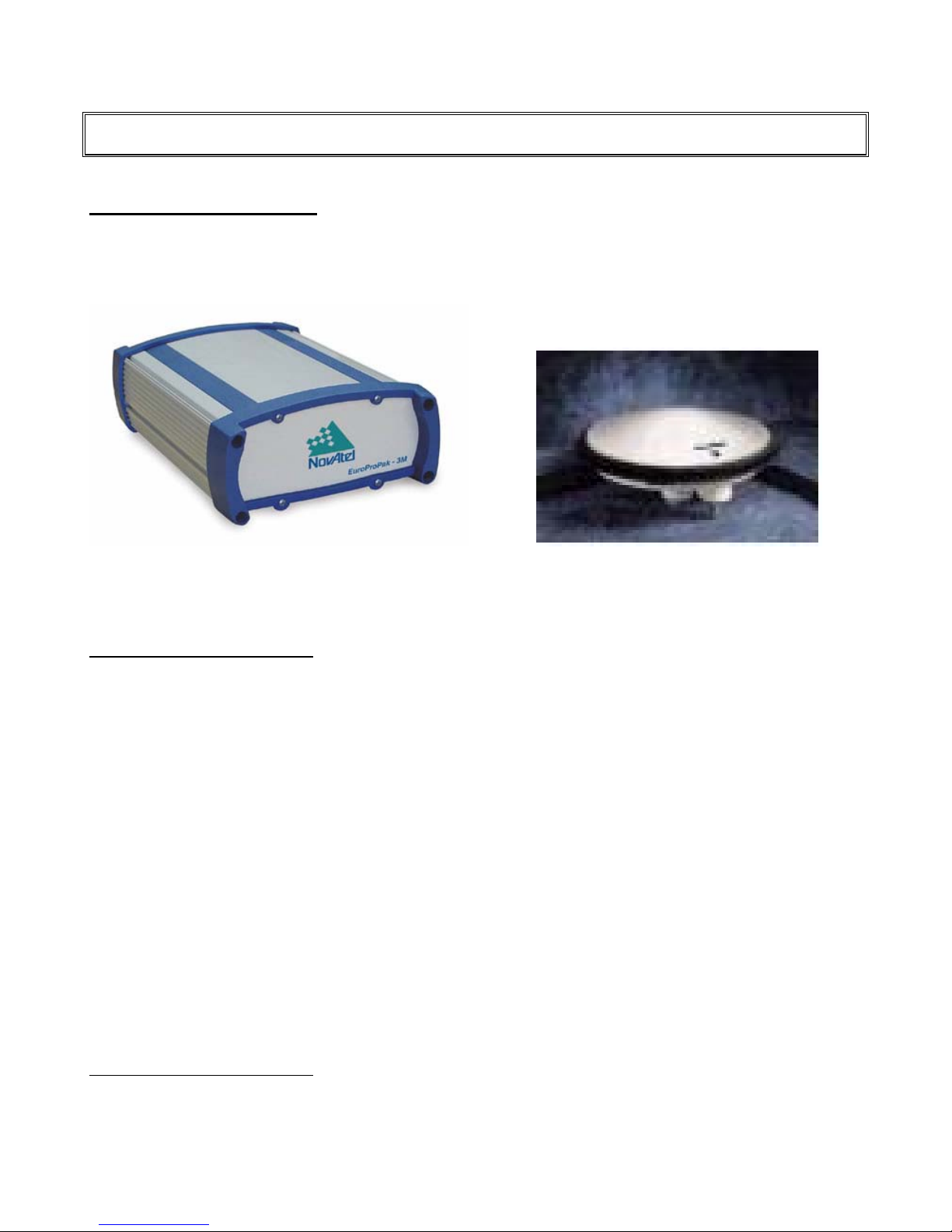
This manual covers the operation of GPS Silicon Valley’s GPS Ionospheric Scintillation and TEC Monitor
(GISTM) system Model GSV4004B. The GSV4004B, with its optional antenna, consists of three major
components: an L1/L2 GPS Antenna (NovAtel’s Model 532, 533 or GPS702), a GPS receiver (NovAtel’s
EuroPak-3M) and a power supply with various interconnecting cables. The EuroPak-3M enclosure houses the
GPS receiver and a low phase noise oven-controlled crystal oscillator (OCXO) that is required for monitoring
phase scintillation. The GPS receiver, the Euro-3M, with modified software (firmware), can track up to 11 GPS
signals signal at the L1 frequency (1575.42 MHz) and the L2 frequency (1227.6 MHz). It measures phase and
amplitude (at 50-Hz rate) and code/carrier divergence (at 1-Hz rate) for each satellite being tracked on L1, and
computes TEC from combined L1 and L2 pseudorange and carrier phase measurements. The 11
dual channels are configured as SBAS satellite tracking channels, and to measure a noise floor for C/N
correction computations. The 11
designated as Channel 12. The last half of the 12
GPS channels (Channel 0 through Channel 9) and 3 SBAS-GEO channels (Channels 10, 11 and 12).
Scintillation measurements are also available on all 3 SBAS-GEO channels. However, the phase scintillation
parameters are somewhat degraded because the SBAS networks are steering the phase of the signal.
Older optional firmware loads assigned only one SBAS-GEO channel with 11 GPS channels. That option is no
longer available.
See Appendix A for specifications for the EuroPak-3M receiver and the L1/L2 antennas. Two CDROMs are
distributed with the GSV4004B – a NovAtel CDROM and a GSV Utilities CDROM. A preliminary manual for the
EuroPak-3M is included on the GSV Utilities CDROM. However, this EuroPak-3M manual should only be used
for the hardware and installation descriptions. The NovAtel data logs from the GSV4004B are based upon
NovAtel’s OEM4 receiver, as the GSV4004B firmware is based upon OEM4 firmware. The OEM4 manuals are
also included on the GSV Utilities CDROM. This GSV4004B manual only augments the NovAtel manuals.
The primary purpose of the GSV4004B GISTM is to collect ionospheric scintillation and TEC data for all visible
GPS satellites (up to 10), and up to 3 SBAS-GEO satellites, and output data logs, called ISMRB or ISMRA, to a
serial port in either binary or ASCII format. Either of two (NovAtel GPSolution4 or SLOG) programs can be used
to control the GSV4004B operations, but SLOG is recommended for collecting scintillation logs. The
GSV4004B’s Data Logging operation can be controlled to collect the ISMR data logs that are generated every
minute. Details of the ISMR data are presented in the GSV4004B Scintillation/TEC Log section. Another offline PC-based program, ISMVIEW4.EXE, may be used to review the ISMR data. Raw 50-Hz phase and
amplitude data logs are also available.
In addition, data extraction programs are supplied for extracting records from the binary files. They are
described within. Example source C++ code is also supplied so the users can write their own extraction
programs.
This manual augments the NovAtel manuals provided with the GSV4004B. Minimum PC requirements are
specified in those manuals. If the high-speed phase and amplitude data logs are to be collected, GSV
recommends using an external high-speed serial port device as a buffer between the GSV4004B and the PC.
The GSV4004B can have serial port output rates as high as 230 kBaud. An example of such a high-speed
serial device is the Inside Out Networks Edgeport USB Expansion Module (www.ionetworks.com
have indicated that certain PC serial ports cannot cope with the high-speed logs.
From time-to-time, there may be GSV4004B firmware upgrades. If there is an upgrade, it will be distributed free
of charge, most likely via email. A section in the manual is devoted to instructions for loading the upgraded
firmware.
th
dual channel is designated as Channels 10 and 11. The 12th dual channel is
th
dual channel is the noise floor channel. Thus, there are 10
th
and 12th
and S4
0
). Test results
1 August 2007
1
GSVGPS Silicon Valley
INSTALLATION
INSTALLING HARDWARE
Figure 1 presents the GSV4004B and an optional antenna (GPS-702 or GPS-702GG)
Panel is described in the NovAtel manual for the EuroPak-3M enclosure. See the applicable NovAtel manuals
for hardware installation instructions.
1
. The GSV4004B Rear
GSV4004B GPS-702 or GPS-702GG L1/L2 Antenna
Figure 1. GSV4004B GPS Ionospheric Scintillation and TEC Monitor and Optional Antenna
INSTALLING SOFTWARE
The NovAtel GPSolution4 software program is distributed on the NovAtel CDROM provided with the
GSV4004B. It can be installed using the “autorun” feature on the CDROM. Then, simply execute the program
from Windows and follow instructions. Consult the NovAtel manuals for operating instructions.
After installation, set up GPSolution4 to recognize the special GISTM logs as follows:
1. Open GPSolution4, and open the appropriate GSV4004B serial port (computer port, not the receiver
port).
2. Select "Update All Convert4 Log Definitions" from the main menu.
3. “Updating Convert4 Conversion Definitions” will appear in the status bar. Once updated, GPSolution4
and Convert4 will be aware of the ISM logs.
4. These procedures are not necessary for subsequent execution of GPSolution4 and Convert4.
GPSolution4 is no longer supported by NovAtel, so it is recommended that SLOG and the parsing utilities
defined herein be used (or other programs developed by the user). The SLOG and other utility programs are
distributed on the second utilities CDROM provided with the GSV4004B. For SLOG and the utility programs,
simply copy all files from the CDROM to a sub-directory you have selected on your hard disk. The SLOG
program manual and example script files used by SLOG are provided on the CDROM, as is this manual.
1
The GSV-702 antenna has been discontinued by NovAtel. The GSV-702GG replaces it and covers the GLONASS band.
However, GLONASS satellites are not tracked by the GSV4004B.
1 August 2007
2

GSVGPS Silicon Valley
RUNNING THE GSV4004B
INITIALIZING THE GSV4004B
The GSV4004B initializes itself upon power-up and begins to acquire satellites using default information. It
automatically locks to the 10 MHz OCXO internal to the enclosure. However, the following non-factory
configuration command should be sent to the receiver to ensure that the GSV4004B provides valid low-phase
noise scintillation parameters:
CLOCKADJUST DISABLE
to disable receiver hardware clock adjustments (to GPS time). These clock adjustments could cause jumps in
the phase data. The downside to this is that clock drift over a very long period of time could cause the
receiver’s time offset from GPS to exceed its limits, but unlikely. Since the clock adjustments should be very
small, the user may chose to not use this command.
Other specific GSV4004B commands controlling filter bandwidths are described later. Default values are set in
the GSV4004B.
RECORDING DATA ON HARD DISK
Either NovAtel’s GPSolution4 or SLOG programs can be used to select data logs from the GSV4004B. These
logs will be continuously recorded to a specified disk file. (It is recommended that SLOG be used to avoid
possible Windows crashes. However, GPSolution4 is excellent for monitoring general receiver performance in
a Windows GUI environment, especially during installation. SLOG is a Windows based program as well that is
executed using the Command Prompt; it does not have a Windows GUI.) The use of SLOG is described in the
SLOG Details Section.
GSV4004B SCINTILATION/TEC LOGS
In addition to the data logs described in the NovAtel manuals, the GSV4004B supports the scintillation/TEC data
logs listed in Table I. For each selected data log, you may also select one the following trigger methods:
Table I. Specific GSV4004B Data Logs
LOG ID BYTE COUNT DESCRIPTION
RAWSINB 327 H + 4 + (n * 420) GISTM 50-Hz phase and amplitude data, and 1-Hz TEC data
(rate = 1 per sec)
DETRSINB 326 H + 4 + (n * 420) GISTM detrended RAWSINB data (rate = 1 per sec)
ISMRB 274 H + 4 + (n*152) GISTM main data record (rate = 1 per 60 sec)
Note: n is the number of SVs being tracked.
RANGEB and RANGEA Data Logs. These NovAtel logs will be slightly different that specified in the
OEM4 manual in that there will be an odd number of observations when a GEO is tracked in the 12th channel
(Channel 11a). Nothing is reported for the noise-floor half of the 12
DATA LOG FORMATS
1 August 2007
3
th
channel (Channel 11b).

GSVGPS Silicon Valley
These three data logs, ISMRB, RAWSINB and DETRSINB, are peculiar to the GSV4004B. Please refer to
NovAtel's GPS OEM4 Receiver User Manuals for detailed descriptions of other data logs.
BINARY LOG STRUCTURE
The structure of the binary messages is given in the NovAtel manuals.
RAWSINB Data Log. The receiver collects raw phase measurements and raw amplitude measurements at
50 Hz rate (i.e. 50 sets of measurements a second) and stores them in the binary RAWSINB data log every
second on the second. Continuous data will be recorded when the ONTIME trigger is specified with 1.0 second
period. Each log contains data blocks for all the satellites being tracked. Each data block contains 50 sets of
data; the first set is at time specified in Time of Week (TOW), the second set at TOW+0.02 seconds, and so on.
The ADR (phase) in this log is that of the tracking model. It contains frequencies up to the tracking loop
bandwidth (default at 10 Hz). This log also includes raw 1-second TEC and ΔTEC data. The format of the
RAWSINB data logs is given in Table II.
The scale factor of the raw power measurements is meaningless. This is because the actual receiver and
antenna gains are unknown. In the end, this does not matter because subsequent detrending and forming of
S4 will normalize the measurements.
The raw phase measurements include satellite motion, the rate of change of the ionosphere and satellite and
receiver oscillator drift. Thus, observation scintillation in the measurements without detrending is not possible,
although the use of FFT programs with windowing may be used without detrending.
DETRSINB Data Log. The DETRSINB data log has the Message ID of 326. The data log is the same
format as the RAWSINB log, with the exception that the data it contains is the receiver-detrended scintillation
data, and the scale of the power measurements is Ratio * 1048576 (ratio of raw to low-pass filtered). The
DETRSINB data logs should not be requested at the same time the RAWSINB data logs are requested to
prevent port overload. The GSV4004B will ignore the second request unless the original request is canceled
(un-logged).
DETRSINB data logs are different if the “60-second averaging” amplitude detrending is selected. If this 60second averaging is selected, the detrended data is simply the raw data divided by the previous 1-minute raw
data average. See more detail on this below under the discussions of the Filter Bandwidth command. Further
detrending (by averaging) is recommended to remove the ambiguity between 60-second intervals.
1 August 2007
4

GSVGPS Silicon Valley
Table II. RAWSINB Data Log - Message ID = 327
Message byte count = H + 4 + (n * 420) (n = the number of SVs being tracked)
Field # Data Bytes Format Units Offset
1 header H 0
2 Number of SV observations 4 integer H
For First SV observation
3 PRN 2 integer H+4
4 reserved 2 H+6
5 L1 TEC at TOW 4 float TECU H+8
6
L1 ΔTEC (1-sec) at TOW
7 First L1 ADR 8 double cycles H+16
8
L1 ΔADR for TOW + 0.00
9 L1 Power for TOW + 0.00 4 unsigned integer (nbp-wbp)*
10
L1 ΔADR for TOW + 0.02
11 L1 Power for TOW + 0.02 4 unsigned integer (nbp-wbp)*
...
107
L1 ΔADR for TOW + 0.98
108 L1 Power for TOW+ 0.98 4 unsigned integer (nbp-wbp)*
109... For Next SV Observation
* See text regarding scale factor (units) for detrended power.
ISMRB Data Log. Both the RAWSINB and the DETRSINB data logs described above contain only raw or
detrended-raw measurements (TEC, TEC-phase, phase and amplitude). They are available for diagnostic or
analytical purposes. The user must supply data analysis programs to process this raw data. A data reduction
program is supplied with the GSV4004B ISM to convert the data to a convenient ASCII format. However, the
receiver automatically reduces these raw measurements every minute on the minute and stores the results in
the ISMRB data log. The GSV4004B provides continuous data at the specified ONTIME (or ONNEW) trigger
with a 60 second period. Each log contains data blocks for the all satellites being tracked, including an SBAS
GEO, if one has been assigned and is visible. The format of the ISMRB data log is given in Table III.
TEC Calculations
the satellite and is reported in TEC Units (TECU = Electrons *10
ionospheric delay between L1 and L2 signals.
TEC = [9.483 * (PR
where:
PR
L2
PR
L1
Δ
C/A-P,PRN
TEC
TEC
TEC (Total Electron Content) is a measure of the number of electrons along the path from
L2
– PR
L1
- Δ
C/A-P,PRN
is the L2 pseudo-range in meters
is the L1 pseudo-range in meters
is the input bias between SV C/A- and P-code code chip transitions in meters (see below)
is the TEC result due to internal receiver L1/L2 delay
RX
is the user defined TEC offset
CAL
4 float TECU H+12
4 signed integer millicycles H+24
/10000
4 signed integer millicycles H+32
/10000
4 signed integer millicycles H+41
/10000
-16
). The number is proportional to the
) + TEC
+ TEC
RX
CAL
] TECU
H+28
H+36
8
H+42
0
1 August 2007
5

GSVGPS Silicon Valley
Table III. ISMRB Data Log - Message ID = 274
Message byte count = H + 4 + (n * 152) (n = number of SVs being tracked)
Field #
Data
1 Header H 0
2 Number of SV observations 4 integer N/A H
For First SV observation
3 PRN 2 integer N/A H+4
4 SV Azimuth angle
5 SV Elevation angle
6 C/N0 8 double dB-Hz H+16
7 Total S4 8 double dimensionless H+24
8 Correction to total S4 8 double dimensionless H+32
9 1-second phase sigma 8 double radians H+40
10 3-second phase sigma 8 double radians H+48
11 10-second phase sigma 8 double radians H+56
12 30-second phase sigma 8 double radians H+64
13 60-second phase sigma 8 double radians H+72
14 Average of Code/Carrier
divergence
15 Sigma of Code/Carrier Divergence 8 double meters H+88
16 TEC at TOW - 45 4 float TECU H+96
17
ΔTEC from TOW - 60 to TOW - 45
18 TEC at TOW - 30 4 float TECU H+104
19
ΔTEC from TOW - 45 to TOW - 30
20 TEC at TOW - 15 4 float TECU H+112
21
ΔTEC from TOW - 30 to TOW - 15
22 TEC at TOW 4 float TECU H+120
23
ΔTEC from TOW - 15 to TOW
24 L1 Lock time 8 double seconds H+128
25 Channel status 4 integer H+136
26 L2 Lock Time 8 double seconds H+140
27 L2 C/N0 8 double dB-Hz H+148
28... For Next SV Observation
Note 1: Data may also be included for SVs that are unhealthy. However, the Azimuth and Elevation may be set
to 0. All scintillation data will still be valid. The TEC values may be set to 0 because of the
unavailability of the Tau_GD value.
is the nominal L1/L2 receiver delay (converted to TECU) hard-coded as a data base parameter, and
TEC
RX
TEC
is an input parameter supplied by the user, since the receiver differential delay may change slightly with
CAL
time, and will be different from unit-to-unit. The units are calibrated against WAAS prior to shipment and the
TEC
value is indicated on the bottom of the unit and on its shipping carton (for shipments after 1 July 2002).
CAL
The TEC is also corrected for satellite inter-frequency biases (Tau_GD – see ICD-GPS-200D), but not for the
SV C/A-to-P biases. These biases are available on a JPL website (see a later section in this document) and
can be input to the GSV4004B during initialization (see below). As an alternative, the values of these biases
can be converted to TECU and added to the logged TEC values.
ΔTEC is based upon carrier phase measurements at L1 and L2. For an ionospheric delay measured in L1
carrier cycles, the total electron content becomes
1
1
Bytes Format Units Offset
4 float degrees H+8
4 float degrees H+12
8 double meters H+80
4 float TECU H+100
4 float TECU H+108
4 float TECU H+116
4 float TECU H+124
1 August 2007
6

GSVGPS Silicon Valley
ΔTEC = (1.1723 ΔPR
over the 1-second interval, where
ΔPR
measured over the 1-second interval (RAWSINB and DETRSINB) or over a 15-second interval (ISMRB).
= 1.54573 (ΔADRL1 – ΔADRL2) cycles
L1,carrier
L1,carrier
) TECU
Phase. As mentioned above for the RAWSINB data log, the receiver collects 50 raw phase measurements a
second. The raw phase measurements are first detrended with a 6th-order Butterworth high-pass filter (with a
user-specified cutoff frequency). Then, for every minute on the minute, the statistics of the residuals (of the
previous 3,000 detrended phase measurements) are computed over periods of 1 second, 3 seconds, 10
seconds, 30 seconds and 60 seconds. Thus, for every 60 seconds, 5 values (1-sec, 3-sec, 10-sec, 30-sec
and 60-sec phase sigma’s) are stored in ISMRB data log along with the time tag (in w eek number and time
of week).
Amplitude. The raw amplitude measurements are detrended (by normalization), either with a 6th-order
Butterworth low-pass filter output (with a user-specified cutoff frequency), or with the measurement average
over the 60-second interval (if the user-specified cutoff frequency is 0). The latter method is the default method
if no cutoff frequency is specified. Then, the total S4, which includes S4 due to the effects of ambient noise
(and multipath), is computed over the same 60-second interval as the phase parameters. The receiver also
computes the correction to the total S4, which is the effect of ambient noise, based upon the average of the
raw 1-Hz C/N
values over the same 60-second intervals.
0
Code/Carrier Divergence. The receiver also collects raw code/carrier divergence (difference between
code and carrier pseudorange) every second. The average and standard deviation of the code/carrier
divergence are then computed every minute on the minute. These values are indicative of multipath (and noise)
activity and can be used to distinguish between S4 due to multipath (and noise) and S4 due to scintillation,
since there is no code/carrier divergence due to scintillation. A method for using the code/carrier divergence
standard deviation is provided below.
L1 Lock Time. The L1 Lock Time indicates how long the receiver has been locked to the carrier phase on
the L1 signal. Since the phase-detrending high-pass filter has to be reinitialized whenever lock is lost, all phase
parameters (sigmas) should be discarded for any Lock Time less than 180-240 seconds (for a 0.1 Hz
bandwidth) to allow the detrending filter to re-settle. For other bandwidths, this time may vary inverseproportionally to the bandwidth. For the S4 parameters, it suffices to only discard data for any Lock Time less
than 60 seconds. S4 may also be valid for Lock Time less than 60 seconds since the power measurements are
non-coherent measurements that do not require phase lock. However, on rare occasions, total signal lock could
have been lost, so the use of S4 for Lock Time less than 60 seconds should be used with caution. However, in
those cases, the code/carrier divergence measurements could be used to discard the data.
L2 Lock Time. The Lock Time indicates how long the receiver has been locked to the carrier phase on the
L2 signal. It is an indicator of the validity of the TEC measurements. As with the L1 phase data, short Lock
Time data should be discarded.
1 August 2007
7

GSVGPS Silicon Valley
GSV4004B SPECIFIC COMMANDS
COMMANDS
The following commands are those in addition to standard NovAtel OEM4 commands:
Filter Bandwidth
This command is used in defining the bandwidths of the phase and amplitude de-trending filters, with default
values of 0.1 Hz and 0 Hz for phase and amplitude data, respectively. These default values may be changed
using the command:
SinBandWidth <PhaseFilterBW> <AmplitudeFilterBW>
This command allows the user to modify the bandwidths of the 6th-order Butterworth filters: a high-pass filter for
detrending raw phase measurements and a low-pass filter for detrending raw amplitude measurements. The
bandwidths may be individually varied between 0.01 to 1.0 Hz (phase) and 0 to 1.0 Hz (amplitude). A 0 Hz
value for the phase filter bandwidth is not valid. If 0 Hz (default value) is input for the amplitude filter bandwidth,
the amplitude detrending is accomplished using a straight 60-second average of the amplitude. This is the most
desirable method with long-fade amplitude scintillation is present, since the Butterworth detrending of amplitude
tends to become unstable and provides excessively large S4 values. However, the straight averaging method is
more susceptible to multipath fading. There is no substitute for a near multipath-free environment.
TEC Calibration Value
This command allows the user to input a TEC Calibration (TEC
An input of zero can be used, in which case measurements may be corrected during post-processing.
SinTECCalibration <CalibrationValue>
As an purchased option, a value calibrated against WAAS provided TEC data is indicated on a sticker under the
unit and on its shipping carton. Typically, with the default value of 0, the units provide TEC values that are on
the order of up to 80 TECU (for the GSV4004B – the values for the GSV4004 and GSV4004A are smaller and
sometimes negative). The value entered should be the value given on the sticker. Antennas can have an effect
on these values. Of course, the user can perform calibration as well and enter a user-determined value.
) value. The use of this value is defined below.
cal
C/A-to-P Biases
As described below, the SVs generally have a time-bias between the C/A and P code chip transitions. In order
to make the TEC values collected from the GSV4004B more accurate, the user may enter these known biases
into the GSV4004B to correct for the biases as TEC data is collected. A specific command has been
implemented. The command is
CPOffset <32 offset values>
The 32 offset values (one for each PRN, in meters) are added to the C/A code pseudorange measurements
prior to forming the TEC values.
PLL Loop Bandwidths
1 August 2007
8

GSVGPS Silicon Valley
Depending upon the environment, it may be necessary to change the L1 and L2 Phase-Lock-Loop bandwidths,
as the loops may have problems acquiring the signal. This is because the default bandwidths are set as narrow
as possible to provide the best tracking performance at lower signal-to-noise ratios. The default bandwidths are
as follows:
L1: 6 Hz
L2 0.2 Hz
The acquisition problem will cause the receiver to “give-up” on a specific signal and never track it, either on L2
alone or on both L1 and L2. If this occurs rarely, nothing should be done. However, if this occurs regularly, the
bandwidths should be increased using the LOOPSBANDWIDTH command as follows:
LOOPSBANDWIDTH [L1 PLL Bandwidth] [L2 PLL Bandwidth]
Care should be exercised using this command. It is an undocumented NovAtel command.
Command Procedure
The procedure for entering commands is given in the NovAtel OEM4 manual, Volume 2. They can either be
entered using GPSolution4 or be entered using SLOG.
TRACKING SBAS (WAAS, EGNOS, MSAS) SVs
COMMANDS
The 11a
even if not visible. To utilize this capability, use the standard Assign Command as follows:
where “10”, “11” and “12” denotes the 11a
required for each SBAS GEO. The current set of PRNs for the SBAS satellites are given in Appendix E.
In all cases, the “b” side of the 12
compute scintillation parameters for the specified SBAS GEO.
In both versions of the SLOG script described below, only one Assign command is included. Add one or two
more commands if additional SBAS GEOs are to be assigned. However, it is advisable to comment out (using ;
at the beginning of the line) commands dealing with the SBAS GEO if no SBAS GEO is visible so that the
receiver is not continually trying to acquire it. This is the Assign command described here. Also, if not within
an SBAS network, collection and copying of the WAAS18B and WAAS26B logs should be commented out as
the data would be useless for the local region where the GSV4004B is located. These logs are collected by
GPS Silicon Valley during GSV4004B testing for the purpose of TEC calibration. Software used to process
these logs is provided on the Utilities CD, but a manual is not. These logs can be converted to ASCII logs using
Convert4. The user may process this data to obtain the SBAS networks estimate of TEC by using procedures
given in RTCA DO-229C. For a nominal fee, GPS Silicon Valley can provide informal instructions (with some
manual manipulation) for using the supplied software (waasiono.exe and VertDelay.exe).
th
, 11bth and 12th channels of the GISTM are to be used to search for and track specified SBAS GEOs,
Assign 10, 11 or 12 <PRN> 0 500
th
channel is used to compute the “Noise Power.” The GISTM will measure or
th
, 11ath and 12th channels, respectively. A separate command is
C/A-TO-P SV BIASES
1 August 2007
9

GSVGPS Silicon Valley
The GSV4004B measures TEC using pseudorange measurements on the L1 and L2 frequencies. On L1, C/A
code measurements are used, while on L2, semi-codeless P code measurements are used. Unfortunately, the
satellite Tau_GD values used for correcting TEC are corrections for P code L1/L2 biases in the SV. There can
also be a bias in the SV between the C/A code phase and the P code phase. This bias will cause a bias in the
TEC output values that is different for each SV. GPS Users involved with the International GPS Service (IGS)
recognized this and have been estimating these C/A-to-P code biases. These biases are available in a file on
the following University of Berne -- http://www.aiub-download.unibe.ch/CODE/P1C1.DCB. The list will be given
in ns as a function of GPS PRN. An example of this file is included on the CDROM provided with the
GSV4004B. This information is periodically updated and may not be available, for a period of time, for new
PRNs, and may be invalid, for a period of time, for PRNs that have had redundant hardware paths changed.
Table IV provides the set of SV biases collected from the site on December 4, 2006, converted to meters. The
number 0 must be inserted for PRNs that do not exist at the time.
Table IV. C/A-to-P SV Biases in Meters (December 4, 2006)
CPOffset -0.0996 -0.0144 -0.132 0.3336 -0.3258 0.0813 -0.3921 -0.1647 0.0459 -0.561 0.1701
0.4803 0.4569 0.0342 -0.5022 -0.2163 0.4176 -0.1068 -0.6057 -0.4053 -0.1239 0.1566
0.0756 -0.0714 0.1404 0.2901 -0.1149 -0.081 0.165 0.5586 0.5112 0
These biases can be removed by using the CPOffset Command upon GSV4004B initialization to enter the
biases, in meters, for each PRN, such as follows:
1 August 2007
10

GSVGPS Silicon Valley
SLOG DETAILS
SLOG
SLOG can be programmed, via script, to generate new files on a periodic basis (such as a new file every day).
Example scripts to do this are given in Appendix B (for recording 60-second data) and Appendix C (for
recording 50-Hz data). The following describes these two sets of script – Scint60sec.slg and ScintRaw.slg.
SLOG revision 6n is required to operate these scripts. Older versions of SLOG will not.
SLOG accepts command line options for Com Port number (integer), file logging period in minutes (double) and
Site Name (string). That is, the command line is:
SLOG scintXXX.slg [iport] [iperiod] [ssite]
where XXX denotes the script name. If the variables are not specified, the default options are 1, 60 and blank
for COM1, 60 minutes, and no site name. The Site Name is the only control the user has over the file names
using the script in Appendix B and C. The file name for each period is as follows: Site Name_GPS Week
No._Day of Week_Hour of Day.gps, relative to GMT.
Scint60sec.slg
This version of script is designed for recording only the 60-second logs, as opposed to the high-rate 50 Hz data.
Either version of script could be used for recording only the 60-second logs. However, ScintRaw.slg always
records temporary 50 Hz data logs, even though it only saves them if parameters exceed thresholds. Saving
the logs can be controlled with appropriate definition of thresholds, however, temporary data logs are always
stored. If the PC serial port cannot handle the high-rate data, this could be a problem. Thus, if the 50-Hz data
is not desired, it is better to use a script that only records 60-second logs. An example of such script is given in
Appendix B.
ScintRaw.slg
Two of the GSV4004B logs (RAWSINB and DETRSINB) consist of a tremendous amount of data, although they
would never be logged simultaneously. Usually, however, these logs do not contain any useful information
when there is not any ionospheric scintillation activity. Thus, it is desired that the logging be selective based
upon information contained in a much lower rate (once per minute) log (ISMRB), which would be logged at the
same time. Unfortunately, this log indicates what had occurred over the previous interval, so some buffering is
required.
The following describes suggestions/requirements for logging either RAWSINB or DETRSINB based upon
information contained in ISMRB.
ScintRaw Requirements
“L” key is pressed. This same information can be used to determine if either the RAWSINB or DETRSINB log
should be recorded. The parameters of interest are SV Elevation angle, C/N
sigma, and L1 Lock time. The idea is to compare each of these (for each SV) against a threshold. If either of
the Total S4 or 60-second phase sigma thresholds are exceeded for any SV, the RAWSINB or DETRSINB log
are recorded for the current period and for N
are exceeded. The thresholds, and the value of N
in Table V.
The counter N is reset to 0 whenever either S4
for any SV, so that the current and the next N
SLOG extracts information from the ISMRB logs and displays the information when the
, Total S4, 60-second phase
0
60-second periods to follow, provided all of the other thresholds
Max
, must be specified in the ScintRaw.slg Script file as given
Max
or Sigma_Phi_60
Min
logs are recorded. It is also be reset when N
Max
and all the other thresholds are exceeded
Min
is reached. An
Max
1 August 2007
11

GSVGPS Silicon Valley
exception to this is applied to data collected from an SBAS GEO – exceeding S60
is not checked for reasons
Min
described below.
Default thresholds (and value of N
) are all 0, which means that all records would be logged. Default values
Max
are used if no values are defined in the ScintRaw.slg Script file.
Table V. Threshold Parameters Specified in ScintRaw Script
Parameter Threshold Range Units
Log Counter N N
SV Elevation Angle El
C/N0 C/N
Total S4 S4
60-Sec Phase Sigma S60
L1 Lock Time Lock
Lock
Logic for recording raw scintillation logs is as follows:
___
save raw Elev Th El C N Th C N
=≥ • ≥
()()
1_44_4
L Lock ThLock S TotalS Th S
()()
•
⎢⎥
+≥ • ≥ •<
()()(
⎢⎥
⎣⎦
≥•≥⎡⎤
1 _ 60 60 _ 60 33
L Lock ThLock S SigPhi Th S PRN
The last term of the logic prevents saving raw data when the Sigma_Phi_60 exceeds the threshold for the SBAS
satellite. This is because the SBAS network is controlling the phase of the SBAS signal and that control could
easily cause the threshold to always be exceeded.
No raw scintillation logs would be recorded if all the thresholds (not including N
(or large) value. However, temporary raw scintillation logs would continue to be recorded.
In order to prevent logging high-rate data on non-scintillation events (low C/N
suggested minimum thresholds are as follows: C/N
sec and Lock
Sig60 = 240 sec. The C/N
Min
SBAS GEO is at a higher elevation angle. The S4
Example ScintRaw.slg script is presented in Appendix C.
0 - 100 Unit-less
Max
0 - 90 Degrees
Min
0 - 60 dB-Hz
0,Min
0 – 1.5 Unit-less
Min
0 - 2 Radians
Min
Min
Min
S4 or
Sig60
0 – 600 Seconds
00
) were set to their maximum
Max
, cycle slips or multipath), the
0
= 30 dB-Hz, S4
0,Min
value could be raised if no SBAS signal is being tracked, or if the
0,Min
value is set to minimize triggering on GPS signal multipath.
Min
= 0.35, S60
Min
)
= 0.2, Lock
Min
S4 = 60
Min
1 August 2007
12

GSVGPS Silicon Valley
OFF-LINE UTILITY PROGRAMS
The following are a few useful off-line utility programs that extract binary scintillation and TEC data logs into an
ASCII format:
Parseismr.exe, Version 1.4.1.0 dated 01/14/04, extracts ISMR records from a binary file and
converts them to comma-delimited ASCII records for a specified PRN
Parseismr <PRN> <inputfile> <outputfile>
If the PRN is specified as “all” (without the quotes), records for all the PRNs will be extracted, but in
time-sequence. The output format, preceded by a comma-delimited header defining the fields, is
given in Table VI. A program such as EXCEL can be used to sort versus PRN. ASCII Azimuth and
Elevation Angle records for all PRNs can also be extracted without the other data with “azel” in the
PRN field. These directions can also be obtained by simply typing the program name. Example
parsed ISMR files are included on the GSV Utilities CDROM as *.XLD files.
Table VI. PARSEISMR Extracted Data Fields
Input
Field #
1 Week Number (WN) N/A
2 Time of Week (TOW) seconds
3 PRN N/A
4 Receiver Status (See NovAtel Manual) N/A
5 SV Azimuth angle degrees
6 SV Elevation angle degrees
7 C/No dB-Hz
8 Total S4 dimensionless
9 Correction to total S4 dimensionless
10 1-second phase sigma radians
11 3-second phase sigma radians
12 10-second phase sigma radians
13 30-second phase sigma radians
14 60-second phase sigma radians
15 Average of Code/Carrier divergence meters
16 Sigma of Code/Carrier Divergence meters
17 TEC at TOW - 45 TECU
18
19 TEC at TOW - 30 TECU
20
21 TEC at TOW - 15 TECU
22
23 TEC at TOW TECU
24
25 L1 Lock time seconds
26 Channel status N/A
27 L2 Lock Time seconds
28 L2 C/N0 dB-Hz
Data Units
ΔTEC from TOW - 60 to TOW - 45
ΔTEC from TOW - 45 to TOW - 30
ΔTEC from TOW - 30 to TOW - 15
ΔTEC from TOW - 15 to TOW
TECU
TECU
TECU
TECU
1 August 2007
13

GSVGPS Silicon Valley
Parsesin.exe, Version 1.4.1.0 dated 01/22/04, extracts RAWSINB or DETRSINB records and
converts them to comma-delimited ASCII records for a specified PRN
Parsesin <PRN> <inputfile> <outputfile> <start_time> <stop_time>
Only a PRN value can be specified (<all> does not work). A PRN value of 0 can be used to display
the number of records available for each PRN. <start_time> and <stop_time> are optional, but are
useful because of the large data file, and to search for data of interest based upon ISMRB summary
results. They are to be entered as GPS Time-of-Week (no Week Number). If <stop_time> is
omitted, data will be parsed to the end of file. If <stop_time> is smaller than <start_time>, the
program will automatically bridge an end-of-week roll-over. Example Parsesin output file data
fields (for a DETRSINB file) are given in Table VII, preceded by a two-line header. Example parsed
DETRSINB files are included on the GSV Utilities CDROM as *.XLD files. The output ADR values
are total ADR values, where the one-second value is combined with each 20-msec value.
Table VII. PARSESIN Extracted Data Fields (Header and First 50 Data Points)
Detrended Week Num: 1231 Prn: 3
GPS TOW TEC TECdot ADR Power
406681 46.409222 0.003973 0.037000 0.99448967
406681.02 46.409222 0.003973 0.034000 1.00279427
406681.04 46.409222 0.003973 0.030000 1.01049423
406681.06 46.409222 0.003973 0.037000 1.00348759
406681.08 46.409222 0.003973 0.040000 1.01587009
406681.1 46.409222 0.003973 0.040000 1.02810955
406681.12 46.409222 0.003973 0.038000 0.96980095
406681.14 46.409222 0.003973 0.037000 0.97975636
406681.16 46.409222 0.003973 0.033000 0.94889641
406681.18 46.409222 0.003973 0.032000 0.94976807
406681.2 46.409222 0.003973 0.035000 1.0243721
406681.22 46.409222 0.003973 0.035000 1.13061142
406681.24 46.409222 0.003973 0.035000 0.95649433
406681.26 46.409222 0.003973 0.036000 1.03944206
406681.28 46.409222 0.003973 0.037000 1.09727955
406681.3 46.409222 0.003973 0.037000 1.15427113
406681.32 46.409222 0.003973 0.042000 0.9800415
406681.34 46.409222 0.003973 0.043000 1.04520988
406681.36 46.409222 0.003973 0.046000 1.00749397
406681.38 46.409222 0.003973 0.044000 0.95614147
406681.4 46.409222 0.003973 0.039000 1.06119061
406681.42 46.409222 0.003973 0.036000 1.09483337
406681.44 46.409222 0.003973 0.034000 1.05533695
406681.46 46.409222 0.003973 0.032000 0.97684574
406681.48 46.409222 0.003973 0.037000 1.00063229
406681.5 46.409222 0.003973 0.040000 0.94757843
The Windows-based program Convert4 is also available as part of the NovAtel GPSolution4
software package. It can also be used to parse logs from logging files. However, before it is
used, GPSolution4 must be setup and used with the GSV4004B so that a file indicating available
receiver logs is recorded in the GPSolution4/Convert4 folder, including synchronizing to the units
data base. This setup is described above for GPSolution4.
(Detrended Log)
1 August 2007
14

GSVGPS Silicon Valley
ISMVIEW4.EXE is an off-line utility program supplied with the GSV4000 that allows the user to
review the ISMR data logs and extract ISM data for specified satellite while ignoring other data
logs. It is a valuable tool for finding desirable data to be extracted from the logs. ISMVIEW4 is
described in Appendix D.
1 August 2007
15

GSVGPS Silicon Valley
SUGGESTED SCINTILLATION ANALYSIS
PROCEDURES
60-SECOND SUMMARY ANALYSIS
For the detailed analysis of the 60-second ISMR summary data, the recommended parsing program is
Parseismr.exe for obtaining the ISMR records in a comma-delimited format as is shown above in Table VI
(using the <all> PRN option). This comma-delimited file can be easily input to and edited in EXCEL, the
Microsoft spreadsheet program. Editing involves eliminating phase sigma data collected before the phase
detrending filter has converged. This can be done by sorting, in ascending order, the Lock Time data in column
25 (column Y) or column 27 (column AA). It is suggested that rows with Lock Time less than 240 seconds be
deleted. Next, in order to eliminate non-converged values even further, sort, in descending order, the 60second phase sigma data in column 15 (column N) and delete rows with very large phase sigma data where
convergence has obviously not yet happened. This will eliminate confusion with legitimate scintillation events.
Filter convergence is not usually an issue with regard to the amplitude S4 data, especially if the “averaging”
detrending option is used. Thus, if the observation of S4 is more important that observation of the phase
sigmas, the Lock Time threshold should be set at a lower value, or generate two different spread sheets with
different Lock Time thresholds.
Finally, sort, in ascending order, the PRNs in column 3 (column C), Week Number I column 1 (column A) and
Time-of-Week in column 2 (column B). The remaining data can then be pasted into the sample spreadsheet
provided with the GSV4004B in columns A through AB. Rows at the end of the spreadsheet may have to be
deleted in there are fewer rows than previously existed in the spreadsheet. If this is the case, the plots will be
automatically adjusted. If there are more rows than previously existed, the series end-points will have to be
adjusted accordingly. We also suggest creating two spreadsheets – one for the GPS PRNs and one for the
SBAS GEO PRN – since their characteristics differ significantly as discussed below.
The Corrected S4 is obtained by differencing the S4 Correction from the Total S4 is an RSS sense. If the S4
Correction is larger than the Total S4, simply set the Corrected S4 to 0, since the S4 value is obviously due to
noise.
The example spreadsheets included on the Utilities CD plot the phase sigmas versus C/N
corrected S4 versus the same and S4 versus an estimate one-sigma pseudorange (code_carrier divergence).
Much of the lower-to-moderate S4 for the GPS PRNs at lower elevation angles can be due to multipath. The
latter plot helps discriminate the difference between the effects of multipath and amplitude scintillation. When
multipath is present, the pseudorange accuracy or the 60-second period is larger than normal (but not always,
depending upon multipath characteristics). In the case of the SBAS GEO, the S4 is somewhat immune to
multipath because the multipath, although present, varies very slowly and filters out in the detrending. However,
because of sometimes much lower C/N
application of the S4 correction partially eliminates this effect.
Example plots of the phase sigmas for the GPS PRNs and the SBAS GEO are presented in Figures 2 and 3,
respectively, for a non-scintillating environment, collected simultaneously. Note that the SBAS values are
somewhat higher for two reasons – lower C/N
GEO signal with updates of once per second.
effect of scintillation would still be observable. The phase sigmas for the GPS PRNs are dominated by the
GSV4004B OCXO phase noise, the SV frequency standard phase noise and thermal noise at low C/N
Generally, the SV frequency standard phase noise is worse than the GSV4004B OCXO phase noise for the
2
Figure 3 represents phase measurements collected from Inmarsat-3. The newer WAAS GEOs, PRNs 135 and 138,
provide much less noisy phase measurements.
conditions, the SBAS GEO Total S4 is more affected by noise. The
0
and the fact that the SBAS network is “steering” the phase of the
0
2
However, under moderate phase scintillation conditions, the
and elevation angle,
0
.
0
1 August 2007
16

GSVGPS Silicon Valley
shorter averaging times, depending upon the frequency standard technology. In any event, lower than
moderate phase scintillation will dominate these effects.
1
0.9
0.8
0.7
0.6
0.5
Sig_Phi - Radians
0.4
0.3
0.2
0.1
0
420000 430000 440000 450000 460000 470000 480000 490000 500000 510000 520000
GPS TOW - Se conds
Sig_Phi_1
Sig_Phi_3
Sig_Phi_10
ElevAngle
C/N0
90
80
70
60
50
40
30
C/N0 - d B-Hz, Elev Angle - Degrees
20
10
0
Figure 2. Example Phase Sigma Plots in a Non-Scintillation Environment for GPS PRNs
Example plots of Corrected S4 for the GPS PRNs and the SBAS GEO are presented in Figures 4 and 5,
respectively, for a non-scintillating environment, collected simultaneously. Note that larger values are more
prevalent for the GPS PRNs than for the SBAS GEO, primarily because of the more rapid changes in the
multipath effects. However, the lower values of Corrected S4 are lower for the GPS PRNs because they are
generally at higher C/N
than is the SBAS GEO.
0
To illustrate the effects of multipath on Corrected S4, examples of estimated pseudorange errors (code-carrier
divergence) are plotted against Corrected S4 for the GPS PRNs and the SBAS GEO in Figures 6 and 7. An
example dividing line between points due to multipath and non-multipath is shown. This technique has been
successfully used to filter out S4 due to multipath from that due to scintillation in a scintillation environment,
since there is very little code/carrier divergence due to scintillation.
Note that the code-carrier measurements on the GPS satellites are somewhat less than on the GEO, but the S4
values on the GEO are somewhat less than on the GPS satellites. Thus, the line equation is different.
1 August 2007
17

GSVGPS Silicon Valley
1
0.9
Sig_Phi_1
Sig_Phi_3
Sig_Phi_10
Sig_Phi_30
50
45
Sig_Phi_60
0.8
ElevAngle
40
C/N0
0.7
0.6
0.5
0.4
Sig_Phi - Radians
0.3
35
30
25
20
15
C/N0 - dB-Hz , Ele v An gle - Deg r e e s
0.2
0.1
0
420000 430000 440000 450000 460000 470000 480000 490000 500000 510000 520000
GPS TOW - Se conds
10
5
0
Figure 3. Example Phase Sigma Plots in a Non-Scintillation Environment for an SBAS GEO
0.9
1
S4
ElevAngle
C/N0
90
80
0.8
0.7
0.6
0.5
Corr ec te d S4
0.4
0.3
0.2
0.1
0
420000 430000 440000 450000 460000 470000 480000 490000 500000 510000 520000
GPS TOW - Seconds
70
60
50
40
30
20
10
0
Figure 4. Example Corrected S4 Plots in a Non-Scintillation Environment for GPS PRNs
El evAn g l e - Deg r ees . C/ N0 - dB-Hz
1 August 2007
18

GSVGPS Silicon Valley
50
45
0.9
0.8
1
S4
C/N0
0.7
0.6
0.5
Corrected S4
0.4
40
35
- dB-Hz
0
C/N
0.3
0.2
30
0.1
0
420000 430000 440000 450000 460000 470000 480000 490000 500000 510000 520000
GPS TOW - Seconds
25
Figure 5. Example Corrected S4 Plots in a Non-Scintillation Environment for an SBAS GEO
1
0.95
0.9
0.85
0.8
0.75
0.7
0.65
0.6
0.55
0.5
0.45
0.4
0.35
0.3
0.25
Sigma_Code_Carrier Divergence - meters
0.2
0.15
0.1
0.05
0
0 0.1 0.2 0.3 0.4 0.5 0.6 0.7 0.8 0.9 1
Sigma_PR < 0. 625 X C orrected_S4 -
Everything above t he l i ne i s likel y
multipath fading plus noise
Corrected S4
Figure 6. Example Estimated Multipath Error Plotted Against Corrected S4 in a Non-Scintillation
Environment for GPS PRNs
1 August 2007
19

GSVGPS Silicon Valley
S
3
2.5
Everythi ng abo ve the line is likely
multipat h fading plus noise
2
1.5
1
Sigma_Code-Carrier - meters
0.5
0
0 0.1 0.2 0.3 0.4 0.5 0.6 0.7 0.8 0.9 1
Sigma _PR < 2.9412 X Correct ed_
Corrected S4
Figure 7. Example Estimated Multipath Error Plotted Against Corrected S4 in a Non-Scintillation
Environment for an SBAS GEO
50-Hz SUMMARY ANALYSIS
As indicated above, without setting thresholds for collection of detrended 50-Hz data, the amount of data
collected can be very excessive. Figure 8 shows the effect of setting thresholds for PRN 2 for a Total S4
threshold set at 0.3, where four 60-second periods of 50-Hz data was collected. This data corresponds to the
Corrected S4 values plotted in Figure 4. N
events. Each 60 second period was detrended again since the buffered amplitude data is detrended with the
previous period’s average during the real time collection. The threshold was exceeded on the first period of
each event, again, due to multipath excursions.
The detrended phase data for the same period is also plotted, but no thresholds were exceeded. Detrending
phase data again is not required since the high-pass filtered data is recorded in real-time. This would also be
the case for the amplitude data if the low-pass filter option was selected with a non-zero bandwidth.
If raw data is collected (not detrended), the user can perform any detrending scheme. However, a word of
caution is in order. If programs such as MATLAB are used for filtering the raw, problems can be encountered –
they are not accurate enough for high-order narrow-bandwidth filtering. This would not be the case if “average”
detrending is used for S4 computations.
was set to 2, so two periods were logged for each of the two
Max
1 August 2007
20

GSVGPS Silicon Valley
6
S4 = 0.395
4
2
0
434500 434550 434600 434650 434700 434750 434800 434850 434900 434950 435000
-2
Detrended Ampl i t ude - dB
-4
-6
Log Powe r
Phase
TOW - Seconds
S4 = 0.365
0.06
0.04
0.02
0
-0.02
-0.04
-0.06
Detrended Phase - radians
Figure 8. Example Detrended Raw Amplitude and Phase Data in a Non-Scintillation Environment for
GPS PRN 2 Where S4 Exceeded 0.3
1 August 2007
21

GSVGPS Silicon Valley
DIRECTIONS FOR LOADING NEW FIRMWARE
Occasionally, a new version of firmware for the GSV4004B will be distributed. To update GSV4004B receiver to
the new version, first launch the application named WINLOAD.EXE. If you had previous versions of
WINLOAD.EXE, please discard them in favor of this new version. You should be running at least
WINLOAD.EXE, v1.0.0.0 A42 (Alpha Release 42). You can verify this by clicking the "Help->About" menu
within WINLOAD.EXE.
When WINLOAD.EXE is started, go to the "Settings->COM Settings" menu and set up the PC's comport for
your system. Going with the default settings is recommended, if possible. COM1, 115200 download baud and
9600 connect baud works good on most systems.
Next, go to the file menu, and select "File Open". In the "File Open" dialog window, navigate to the directory
containing the new firmware HEX file (if necessary), and then double-click on the HEX file. The "File Open"
dialog box will disappear, and the path and file should appear in the console window. Connect your OEM4's
COM1 port to the appropriate PC's comport using the "null" modem cable, have power ready, but DO “NOT”
apply it to the GSV4004B yet. Click the "Write Flash" button. Double-check that the power is unplugged to the
GSV4004B receiver when prompted by the dialog box, click "Ok", and then plug power back into the GSV4004B
about three seconds after the status screen says "Searching for card ... timeout in: 15 s". You will get the best
results if you apply power at 12 seconds. (If the countdown starts at 60 instead of 15, then wait until it counts
down to 57, then apply the power.)
The card will be initialized, and then you will be prompted for the authorization code (authcode) for this particular
GSV4004B Card (serial number specific). (Note that there are two serial numbers – one for the enclosure and
one for the receiver card. The receiver card serial number is not visible, but is indicated along with the
enclosure serial number in the documentation provided with the authcode.) Enter the authcode complete with
the commas, making sure that you enter the letters in the authcode in UPPERCASE FORMAT ONLY, and then
click OK to begin the firmware update process. (Lowercase or mixed case will not work properly, and you will
get an error about an invalid authcode or a failed checksum.)
Note: You have thirty seconds to enter the authcode before WinLoad "times out" and aborts the firmware
loading process. It helps to copy the authcode to the clipboard and then paste the authcode to WinLoad's
"authcode entry text dialog box" using Ctrl-V to save time, and also to reduce the chance of entering an
incorrect authcode due to a typing error.
Once the GSV4004B has been successfully loaded with the new firmware, you “MUST” FRESET the receiver or
it may operate erratically, because the NVRAM table has changed, so you must use the FRESET command to
"format" the NVRAM table to new firmware’s specifications for reliable operation. You can FRESET the
receiver by entering the FRESET command into it using a simple terminal program or by using the "Command
Console" window under the GPSolution4 software.
1 August 2007
22

GSVGPS Silicon Valley
APPENDIX A – EuroPak-3M and L1/L2 Antenna Data
Sheets
1 February 2007
1

Euro-3M
Euro-3M
NovAtel’s Euro-3MTM features improved MEDLL performance and
signal quality measurements in a Euro format card or a durable,
lightweight enclosure with optional internal high precision clock.
Standard and MEDLL versions
Available in two software models, the standard Euro-3M includes
14 channels for tracking L1/L2 GPS signals with NovAtel’s patented
Narrow Correlator® technology and four channels for wide correlator
tracking of L1 GEOs. The MEDLL version provides eight L1/L2
GPS channels and one L1 GEO channel and features a 50 percent
improvement in MEDLL performance on a single card, compared
to the previous multi-card 8 MHz MEDLL receiver, as shown in
Figure 1 (back).
Superior tracking ability
The Euro-3M includes the patent-pending SafeTrakTM algorithm,
which detects and eliminates cross-correlation for added tracking
reliability. In addition, the Euro-3M features bit synchronization
verification, in-band digital pulse blanking on the L2 signal, and
includes RFI improvements developed for the U.S. WAAS network.
A DO-228 compatible RF deck offers additional protection against
out-of-band RF interference.
Raw data and signal quality monitoring
The Euro-3M provides raw GPS and SBAS frame data with parity
information and Signal Quality Monitoring (SQM) measurements,
which can be used to monitor the quality of the incoming signal and
detect satellite failures. Automatic gain control (AGC) data for the
L1 and L2 signals is also provided.
Choice of platform
Designed for system integrators, the Euro-3M is available as an
OEM engine in the standard Eurocard format or housed in the
rugged EuroPak-3M enclosure. Both include three high speed serial
ports and auxiliary strobe signals, including a 1PPS output. Also
available is the EuroPak-3MT, which provides these same features,
as well as an internal high precision clock tightly matched to GPS
time, making it an ideal solution for timing applications.
Features Bene ts
50% improvement in MEDLL performance Reduces multipath effects for accurate range measurements
Real-time Signal Quality Monitoring (SQM) measurements using
multiple correlators
In-band digital pulse blanking on the L2 signal Mitigates pulsed RF interference for increased tracking reliability
Offers the ability to detect satellite failures to ensure exceptional
data integrity
WAAS Engines & Enclosures

Euro-3M
�
������������
���
Performance
1
Tracking Channels
Standard Model 14 L1/L2 GPS + 4 L1 GEO
MEDLL Model 8 L1/L2 GPS + 1 L1 GEO
Position Accuracy
Single Point L1/L2 1.5 m CEP
Measurement Precision
2
C/A Code 10 cm RMS
P(Y) Code 50 cm RMS (AS on)
L1 Carrier Phase 3 mm RMS
(differential channel)
L2 Carrier Phase 5 mm RMS
(differential channel)
Data Rate 1 Hz
Time to First Fix
Cold Start3 < 100 s
Signal Reacquisition
C/A Code < 5 s (typical)
P(Y) Code < 60 s (typical)
SBAS < 10 s (typical)
Altitude 3,000 m
1 Typical values. Performance specifications subject to GPS system characteristics,
US DOD operational degradation, ionospheric conditions, satellite geometry,
baseline length, and multipath effects.
2 Measurement precision at C/No = 44 dB-Hz.
3 Typical value. No almanac or ephemeris and no approximate time or position.
4 Main data connector extends approximately 7 millimeters past edge of board.
5 Unless otherwise specified, all specifications apply to both the EuroPak-3M and
EuroPak-3MT.
6 The EuroPak-3M provides an external oscillator input on this connector while the
EuroPak-3MT provides an output from the internal clock.
Figure 1 - Simulation of Pseudorange Error Due to Multipath
Euro-3M Engine
Physical & Electrical
Size4 160 x 100 x 16 mm
Weight 150 g
Power
Input Voltage +4.5 to +18 VDC
Power Consumption 6 W (typical)
Antenna LNA Power Output
Output Voltage +5 VDC
Maximum Current 100 mA
External Oscillator Input
Input Frequency 5 or 10 MHz ± 0.5 ppm
Signal Level 0 to +13 dBm
Communication Ports
• 3 RS-232 or RS-422 serial ports
(user-configurable) capable of 9,600 to
230,400 bps
Input/Output Connectors
Main 160-pin five-row male header
Antenna Input SMB male
External Oscillator Input SMB male
Environmental
Temperature
Operating -40°C to +85°C
Storage -45°C to +95°C
Humidity 95% non-condensing
EuroPak-3M/3MT Enclosure
Physical & Electrical
Size 235 x 154 x 71 mm
Weight 1.2 kg
Power
EuroPak-3M
Input Voltage +9 to +18 VDC
Power Consumption 6 W (typical)
EuroPak-3MT
Input Voltage +11 to +18 VDC
Power Consumption 13 W (typical)
Antenna LNA Power Output
Output Voltage +5 VDC
Maximum Current 100 mA
External Oscillator Input (EuroPak-3M only)
Input Frequency 5 or 10 MHz ± 0.5 ppm
Signal Level 0 to +13 dBm
Oscillator Output (EuroPak-3MT only)
Output Frequency 10 MHz
Signal Level +10 dBm ± 3 dB
Phase Noise
0.1 Hz -55 dBc/Hz 1 kHz -165 dBc/Hz
1 Hz -95 dBc/Hz 10 kHz -165 dBc/Hz
10 Hz -125 dBc/Hz 100 kHz -165 dBc/Hz
100 Hz -155 dBc/Hz
Communication Ports
• 3 RS-232 serial ports capable of 9,600
to 230,400 bps
Input/Output Connectors
Power 4-pin LEMO
Antenna Input TNC female
Oscillator6 BNC female
COM1 DB-9 male
COM2 DB-9 male
COM3 DB-9 male
I/O DB-9 female
5
Environmental
Temperature
Operating
EuroPak-3M -40°C to +60°C
EuroPak-3MT -20°C to +50°C
Storage -45°C to +95°C
Humidity 95% non-condensing
For more information, visit our website.
U.S. & Canada
Europe
Other
Fax
Email
Web
Version 1 - Specifications subject to change without notice.
© 2004 NovAtel Inc. All rights reserved. Printed in Canada. D04670
1-800-NovAtel
+44 (0) 1524 848 374
+1-403-295-4900
+1-403-295-4901
sales@novatel.ca
www.novatel.com

GPS-702
The GPS-702 is an active antenna
designed to operate at the GPS L1
and L2 frequencies, 1575.42 and
1227.60 MHz. This guide provides
the basic information you need to
install and begin using your new
antenna.
ADDITIONAL EQUIPMENT REQUIRED
The equipment listed below is required to set up the GPS-702:
• A mount, such as a range pole, tribrach, or tripod, with a
5/8" x 11 thread that extends between 3/8" and 7/8" (9
mm and 22 mm)
• A 1" open-end wrench
• Coaxial cable with a male TNC connector
• A device with an antenna input port that both receives
the RF signal and provides 4.5 - 18.0 VDC to the
antenna (All NovAtel GPS receivers provide the necessary power through their antenna RF connectors.)
SITE SELECTION GUIDELINES
Before installing the antenna, select a site that as closely as
possible meets the following conditions for optimal performance:
• An unobstructed line-of-sight from horizon to horizon
and at all bearings and elevation angles
• As far as possible from reflective objects, especially
those that are above the antenna and any water bodies,
which can be a strong source of multipath reflections
• If obstructions and reflective surfaces are within 30 m,
ensure the site is as high as possible. Otherwise, mount
the antenna as low as possible.
INSTALLING THE ANTENNA
After a site has been selected, install the antenna as follows.
1. Verify that the thread on the mount does not extend more
than 7/8" (22 mm) to ensure the plastic inside the antenna
receptacle is not damaged when the mount is inserted. If it
extends further than 7/8" (22 mm), add two jam nuts to
shorten the exposed thread, ensuring the nuts are well-tightened.
2. Align the mount thread with the metal adapter on the bottom
of the antenna and rotate the antenna clockwise until it is
securely screwed to the mount. Using a wrench, tighten the
adapter to the mount.
The metal adapter on the bottom of the antenna is fixed in place.
Do not attempt to remove it.
3. Remove the dust cap from the antenna’s TNC connector.
4. Attach the male TNC connector of the coaxial cable to the
antenna’s TNC connector.
5. Attach the other end of the coaxial cable to the antenna input
port of the receiving device, which must provide power as
detailed in the SPECIFICATIONS section of this guide. All
NovAtel GPS receivers provide the necessary power
through their antenna RF connectors.
ANTENNA CARE
The GPS-702 is designed to withstand the elements, including
rain, snow, and dust. However, to ensure your antenna performs
optimally, keep the radome (the top surface of the antenna)
clean and brush off any ice and snow. In addition, ensure the
TNC connector remains clean and dry and replace the dust cap
when a cable is not connected.
ELEVATION GAIN PATTERN
SPECIFICATIONS
USERS’ GUIDE
5/8 x 11
thread
"
3/8 - 7/8 9 - 22 mm"" (
)
Mount
Metal
adapter
Jam nuts
or flange
TNC connector
Coaxial
cable
RF
3 dB pass band (typical)
L1: 1575 -15/+30 MHz
L2: 1228 -15/+30 MHz
Out-of-band rejection (typical)
-30/+50 MHz
-40/+80 MHz
30 dBc
50 dBc
Gain at zenith (θ = 90°) (min)
L1: +5 dBic L2:+2 dBic
Gain roll-off (zenith to horizon) L1:13 dB L2:11 dB
LNA gain (typical) 27 dB
Polarization Right-hand circular
Noise figure (typical) 2.0 dB
L1-L2 differential propagation
delay (maximum)
5 ns
Nominal impedance 50 Ω
VSWR ≤ 2.0 : 1
POWER
Input voltage 4.5 - 18.0 VDC
Current (typical) 35 mA
PHYSICAL
Diameter
185 mm (7.28
")
Weight 480 g (16.9 oz)
ENVIRONMENTAL
Maximum altitude 9000 m (29527.5 ft)
Operating temperature -40°C to +85°C (-40°F to +185°F)
Storage temperature -55°C to +85°C (-67°F to +185°F)
Vibration MIL-STD-810F Method 514.5
Salt spray MIL-STD-810F Method 509.4
Ingress protection IPX6, IPX7

MECHANICAL DRAWINGS PHASE CENTER
Please refer to the Mechanical Drawings on the previous panel
and the close-up of the label below before reading this section.
Height = Vertical phase center offset from antenna reference
point or antenna reference plane (ARP)
For relative offset numbers and phase center variation (PCV)
tables, please visit the U.S. National Geodetic Survey (NGS)
website at www.ngs.noaa.gov/ANTCAL/.
For absolute offset numbers and to download PCV tables,
please visit the GEO++ website at www.geopp.com.
When using either of the websites mentioned above, look for the
NovAtel listing of your antenna model and its hardware revision.
Only integer hardware revisions affect the phase center offsets. For
example, the numbers given for hardware revision 2.02 are applicable to an antenna labelled H/W Rev: 2.00, 2.04, 2.12 and so on.
Table1 shows typical absolute and relative offset numbers for
the current 702 antenna model.
Table 1: Height
If you need any further advice on this matter, please visit our
website at www.novatel.com. Other methods of contacting
Customer Service can be found on the last panel of this guide.
WARRANTY POLICY
NovAtel Inc. warrants that its Global Positioning System (GPS)
products are free from defects in materials and workmanship,
subject to the conditions set forth below, for the following periods
of time:
GPSAntenna™ Modules: One (1) Year
Cables and Accessories: Ninety (90) Days
Date of sale shall mean the date of the invoice to the original
customer for the product. NovAtel's responsibility respecting this
warranty is limited solely to product repair at an authorized
NovAtel location only. Determination of repair will be made by
NovAtel personnel or by technical personnel expressly authorized by NovAtel for this purpose.
The foregoing warranties do not extend to
(i) nonconformities, defects or errors in the products due to acci-
dent, abuse, misuse or negligent use of the products or use in
other than a normal and customary manner, environmental
conditions not conforming to NovAtel’s specifications, or failure
to follow prescribed installation, operating and maintenance
procedures, (ii) defects, errors or nonconformities in the products
due to modifications, alterations, additions or changes not made
in accordance with NovAtel’s specifications or authorized by
NovAtel, (iii) normal wear and tear, (iv) damage cause by force
of nature or act of any third person, (v) shipping damage; or (vi)
service or repair of product by the dealer without prior written
consent from NovAtel.
In addition, the foregoing warranties shall not apply to products
designated by NovAtel as beta site test samples, experimental,
developmental, preproduction, sample, incomplete or out of
specification products or to returned products if the original identification marks have been removed or altered.
The warranties and remedies are exclusive and all other warranties, express or implied, written or oral, including the implied
warranties of merchantability or fitness for any particular purpose
are excluded.
NovAtel shall not be liable for any loss, damage or expense
arising directly or indirectly out of the purchase, installation,
operation, use or licensing or products or services. In no event
shall NovAtel be liable for special, indirect, incidental or consequential damages of any kind or nature due to any cause.
There are no user-serviceable parts in the GPSAntenna and no
maintenance is required. If the unit is faulty, replace with another
unit and return the faulty unit to NovAtel Inc. You must obtain a
RETURN MATERIAL AUTHORIZATION (RMA) number by
calling NovAtel Customer Service at 1-800-NOVATEL (U.S. and
Canada only) or 403-295-4900 before shipping any product to
NovAtel or a dealer. Once you have obtained an RMA number,
you will be advised of proper shipping procedures to return any
defective product. When returning any product to NovAtel,
please return the defective product in the original packaging to
avoid damage.
Before shipping any material to NovAtel or Dealer, please obtain a
Return Material Authorization (RMA) number from the point of purchase. You may also visit our website at http://www.novatel.com
and select Support | Repair Request from the side menu.
PATENT NOTICE
NovAtel’s 700 series antennas are manufactured and protected
under U.S. Patent:
#6,445,354
#6,452,560
QUESTIONS OR COMMENTS
If you have any questions or comments regarding your 700
series antenna, please contact NovAtel Customer Service using
one of methods provided below.
Email: support@novatel.ca
Web: www.novatel.com
Phone: 1-800-NOVATEL (U.S. & Canada)
403-295-4900 (International)
Fax: 403-295-4901
© Copyright 2002, 2003 NovAtel Inc. All rights reserved.Printed in Canada on recycled
paper. Unpublished rights reserved under international copyright laws. Recyclable.
OM-20000075 Rev 5 July 31, 2003
TOP
VIEW
BOTTOM
VIEW
1
00
60.6
69.
1
Ø185
Ø170
194.5
SIDE
VIEW
Height
A
ll dimensions are in millimeters (mm)
where 1 inch = 25.4 mm
= PHASE CENTER
Tape measure
station
H/W Rev: 1.00 P/
N
: 0101xxxx
MADE IN CANADA www.novatel.ca
NVH99999999
GPS-70x A
N
TE
N
N
A
ARP
100 mm
40 mm
A
RP
4
.
5
-
1
8
V
D
C
5
0
m
A
m
a
x
.
65 mm
Absolute (GEO++)
Relative (NGS/IGS)
L1
66 mm (2.60”) 83 mm (3.27”)
L2
63 mm (2.48”) 77 mm (3.03”)
Avg.
65 mm (2.56”) N/A
H/W Rev: 1.00 P/N: 0101xxxx
MADE IN CANADA www.novatel.ca
NVH99999999
GPS-70x ANTENNA
Antenna model
Hardware Revision

GPS-600-LB
L1/L2 Antennas
GPS-702
GPS-533
GPS-532
L1/L2 Antennas
NovAtel’s L1/L2 antennas combine exceptional performance with
unsurpassed reliability to suit a wide variety of applications.
GPS-702
The GPS-702 includes patented Pinwheel™ technology to provide
superior multipath rejection in a compact and lightweight dualfrequency antenna. With a highly stable phase center in the same
location for the L1 and L2 signals, the antenna is the perfect choice
for high precision applications. The GPS-702 is waterproof to
IEC 60529 IPX7 and meets the MIL-STD-810F specification for
vibration and salt spray, resulting in an antenna suitable for adverse
conditions.
GPS-533
The GPS-533 is a high performance L1/L2 antenna with a builtin choke ring to substantially reduce the effects of multipath,
making it ideal for use in a DGPS base station or other demanding
Features Bene ts
applications. The antenna features an integrated protective radome
to withstand harsh environments and meets DO-160D standards.
GPS-532 and GPS-532-C
NovAtel’s GPS-532 is an aircraft-certified L1/L2 antenna for airborne
and other high dynamic applications. Designed to the ARINC 743A
standard, the GPS-532 weighs less than 200 grams and includes a
four hole mounting system for secure installation. The GPS-532-C
includes an FAA airworthiness certificate.
GPS-600-LB
The GPS-600-LB provides access to the OmniSTAR L-band and
GPS L1 and L2 frequencies for decimeter level accuracy when
combined with the ProPak®-LB plus. With a rugged, compact
housing suitable for extreme environments and high vibration
applications, the GPS-600-LB is ideal for precision agriculture,
marine, and mobile applications.
Choice of specialized antennas
Wide input voltage range Ensures compatibility with virtually all GPS receivers
Rugged, environmentally sealed housings
Offers performance and a form factor optimized to meet the
needs of your application
Provide reliability in a wide range of severe environments and
applications
L1/L2 Antennas

L1/L2 Antennas
0˚
30˚
60˚
90˚
0 dB
-20 dB
-40 dB
GPS-533 L1
Peak = 7.7 dBic
0˚
30˚
60˚
90˚
0 dB
-20 dB
-40 dB
GPS-533 L2
Peak = 4.7 dBic
0˚
30˚
60˚
90˚
0 dB
-20 dB
-40 dB
GPS-532 L1
Peak = 4.7 dBic
0˚
30˚
60˚
90˚
0 dB
-20 dB
-40 dB
GPS-532 L2
Peak = 3.3 dBic
Receiver Compatibility
All antennas listed on this page are
designed for use with NovAtel’s
OEM4-based receivers or other
equivalent high-precision GPS
receivers.
GPS-702
For more specifications on the GPS-702, see the
GPS-700 Series product sheet.
3 dB Pass Band
L1 1575 -15/+30 MHz (typical)
L2 1228 -15/+30 MHz (typical)
Out-of-Band Rejection (
ƒ
-30/+50 MHz 30 dBc (typical)
c
ƒ
-40/+80 MHz 50 dBc (typical)
c
ƒ
= L1, L2)
c
LNA Gain 27 dB (typical)
Gain at Zenith (90°)
L1 +5 dBic (minimum)
L2 +2 dBic (minimum)
Noise Figure
≤
2.0 dB (typical)
GPS-600-LB
For more specifications on the GPS-600-LB, see
the GPS-600-LB product sheet.
3 dB Pass Band
L1 1575 ± 10 MHz (typical)
L2 1228 ± 10 MHz (typical)
L-band 1520 - 1565 MHz (typical)
Out-of-Band Rejection
L1, L-band
1420 MHz 40 dBc (typical)
1675 MHz 45 dBc (typical)
L2
ƒ
-100 MHz 50 dBc (typical)
c
ƒ
-50/+100 MHz 30 dBc (typical)
c
ƒ
+50 MHz 20 dBc (typical)
c
LNA Gain
L1, L2 26 ± 3 dB (typical)
L-band 29 ± 3 dB (typical)
Gain at Zenith (90°)
L1 +6 dBic (minimum)
L2 +6 dBic (minimum)
L-band +5 dBic (minimum)
Noise Figure
≤
2.6 dB (typical)
GPS-533
Performance
3 dB Pass Band
L1 1575 ± 13 MHz (typical)
L2 1227 ± 13 MHz (typical)
Out-of-Band Rejection (
ƒc
± 50 MHz 40 dBc (typical)
LNA Gain
L1 31 ± 2 dB (typical)
L2 33 ± 2 dB (typical)
Gain at Zenith (90°)
L1 +7.7 dBic (minimum)
L2 +4.7 dBic (minimum)
Gain Roll-Off (from Zenith to Horizon)
L1 15 dB
L2 18 dB
Noise Figure
VSWR
Physical & Electrical
Size
Diameter 308 mm
Height 223 mm
Weight 4.1 kg
Power
Input Voltage +2.5 to +24 VDC
Power Consumption 1 W (typical)
Operating Temperature -55°C to +85°C
Regulatory FCC Class B, CE
GPS-533 and GPS-532
Elevation Gain Patterns
The plots to the right
represent the typical righthand polarized normalized
radiation pattern for the L1
and L2 frequencies. The
plots on the left are for the
GPS-533 antenna and the
plots on the right are for the
GPS-532 antenna.
ƒ
= L1, L2)
c
≤
3.0 dB (typical)
≤
1.5 : 1
GPS-532 / GPS-532-C
Performance
3 dB Pass Band
L1 1575 ± 12 MHz (typical)
L2 1227 ± 12 MHz (typical)
Out-of-Band Rejection (
ƒc
± 50 MHz 40 dBc (typical)
LNA Gain
L1 31 ± 2 dB (typical)
L2 33 ± 2 dB (typical)
Gain at Zenith (90°)
L1 +4.7 dBic (minimum)
L2 +3.3 dBic (minimum)
Gain Roll-Off (from Zenith to Horizon)
L1 6.5 dB
L2 7.1 dB
Noise Figure
VSWR
Physical & Electrical
Size 19 x 76 x 119 mm
(Conforms to ARINC 743A)
Weight 198 g
Power
Input Voltage +2.5 to +24 VDC
Power Consumption 1 W (typical)
Operating Temperature -55°C to +85°C
Regulatory FCC Class B, CE
For more information, visit our website.
ƒ
= L1, L2)
c
≤
3.0 dB (typical)
≤
1.5 : 1
U.S. & Canada
Europe
Other
Fax
Email
Web
Version 1A - Specifications subject to change without notice.
© 2004 NovAtel Inc. All rights reserved. Printed in Canada. D05466
1-800-NovAtel
+44 (0) 1524 848 374
+1-403-295-4900
+1-403-295-4901
sales@novatel.ca
www.novatel.com

GSV
24 February
GPS Silicon Valley
2004
5
APPENDIX B – EXAMPLE SLOG SCRIPT FOR RECORDING HIGH-
RATE (50 Hz) LOGS
;
; Script to log raw scintillation data if the threshold parameters are
; exceeded.
;
; Go to the end of the script to see the different ways the script executed
; may be called from the DOS prompt.
;
; Parameter definition subroutine
sub ParameterDefinition \
int iHighScintDuration& \
double dElevation& \
double dCno& \
double dS4Lock& \
double TotalS4& \
double d60SecPhaseSigmaLock& \
double d60SecPhaseSigma& \
string sRawDataLog&
;
; Modify threshold parameters here
;
iHighScintDuration = 2 ; Length of time to log raw data after a
; high scintillation moment in minutes,
; must be 1 or greater
dElevation = 5.0 ; Elevation angle Threshold
dCno = 35.0 ; C/No Threshold
dS4Lock = 60.0 ; S4 Lock Time Threshold
TotalS4 = 0.3 ; Total S4 Threshold
d60SecPhaseSigmaLock = 240.0 ; 60-Sec Phase Sigma Lock Time Threshold
d60SecPhaseSigma = 0.2 ; 60-Sec Phase Sigma
sRawDataLog = "detrsinb" ; Type of raw data to be logged
; "rawsinb" or "detrsinb"
return
; Main logging subroutine
sub log int iPort double dFilePeriod string sSite

GSVGPS Silicon Valley
APPENDIX B – EXAMPLE SLOG SCRIPT FOR PERIODIC FILES FOR
RECORDING 60-SECOND LOGS
; Main logging subroutine
sub log int iPort double dLogPeriod string sSite
; Convert minutes into seconds
dLogPeriod = dLogPeriod*60
;-------------------------------------------------------------
testname "Scintillation Monitor Data Logging"
;Initiate communication with Novatel via COMx on PC
find com%iPort% 57600 receiver none
pause 60 ; Give the enough time for the find to do its job
define string sSerialNumber
sSerialNumber = serialnumber("receiver", 0)
send * "ecutoff 5\r" ; minimum elevation angle
send * "SinBandWidth 0.1 0.0\r" ; sets phase and amplitude detrending cutoffs
send * "SinTECCalibration 0\r" ; removes bias in TEC measurements
send * "assign 11 122 0 500\r" ; assigns an SBAS GEO to channel 11
send * "clockadjust disable\r" ; disables receiver clock adjustments
; enter PRN C/A-to-P offsets
send * "CPOFFSET -0.0321 -0.3186 0.0447 0.4605 -0.267 0.1788 -0.1854 -0.1539 0.096 -0.4974 0.2265 0 0.4677
0.1281 -0.2841 -0.0855 -0.2574 0.0255 0 -0.3057 -0.0801 -0.4266 -0.2235 0.1035 0.1833 0.3966 0.0015 -0.0288
0.2868 0.6195 -0.0732 0\r"
pause 5
; Wait for time to be set
send * "log rangeb ontime 5.0\r"
label WaitForTime
jump TimeIsSet gpsset() == TRUE
pause 1.0
jump WaitForTime
1 August 2007
1

GSVGPS Silicon Valley
label TimeIsSet
; Make sure the script doesn't start near the rollover so that the GPS
; week number and weekseconds are from the same week
jump WaitForTime GPSWEEKSECS() > 604800.0-10.0
;---------------------------------------------------------------------
; Start logging (hourly) data files
define double dGpsWeek ; GPS week number
define double dGpsWeekSecs ; Seconds into the week
define double dHourOfWeek ; Hour into the week
define double dDayOfWeek ; Day into the week
define double dHourOfDay ; Hour into the day
define string gpsfile ; Name of the file
define double dStopWeekSecs ; Seconds into the week at end of file
let dGpsWeek = GPSWEEK()
; GpsWeekSecs aligned with interval
let dGpsWeekSecs = (floor(GPSWEEKSECS()/dLogPeriod))*dLogPeriod
; Loop Forever
label again
; GPS file name
let dHourOfWeek = FLOOR(dGpsWeekSecs/3600.0) ; Hour of week
let dDayOfWeek = FLOOR(dHourOfWeek/24.0) ; Day of week
let dHourOfDay = dHourOfWeek - dDayOfWeek*24.0 ; Hour of day
print "dHourOfWeek = %dHourOfWeek%"
print "dDayOfWeek = %dDayOfWeek%"
print "dHourOfDay = %dHourOfDay%"
let gpsfile = "%4.0dGpsWeek%\%sSite%%4.0dGpsWeek%_%1.0dDayOfWeek%_%02.0dHourOfDay%"
; Start the logging until the next hour
connect com%iPort% 57600 %gpsfile%_%sSerialNumber% noappend ; start a new file
send * "log versiona once\r"
send * "log rxconfiga once\r"
send * "log rxstatuseventa onchanged\r"
1 August 2007
2

GSVGPS Silicon Valley
; Following commands set up logs -- last two are for collecting WAAS
; Ionospheric Correction Data to use for TEC Calibration
send * "log bestposa ontime 60.0\r"
send * "log ismrb onnew\r"
send * "log rangeb ontime 60.0\r"
send * "log waas18B onchanged\r"
send * "log waas26B onchanged\r"
let dStopWeekSecs = dGpsWeekSecs+dLogPeriod
; Log until the end of the logging interval
gpstime %.0dGpsWeek% %6.0dStopWeekSecs%
; Increase GPS week seconds
let dGpsWeekSecs = dGpsWeekSecs + dLogPeriod
if dGpsWeekSecs >= 604800.0
let dGpsWeek = dGpsWeek + 1
let dGpsWeekSecs = dGpsWeekSecs - 604800.0
endif
jump again ; Do this until operator hits "Q"
; Unreachable
return
; Default main of port 1, new file every hour, no site name
main
gosub log 1 60.0 ""
end
; When the user defines a port number, default to a new file every hour, no site name
main int iPort
gosub log iPort 60.0 ""
end
; When the user defines a port number and the number of minutes per file, no site name
main int iPort double dPeriod
gosub log iPort dPeriod ""
end
1 August 2007
3

GSVGPS Silicon Valley
1 August 2007
4
; When the user defines a port number and the number of minutes per file and a site name
main int iPort double dPeriod string sSite
string sSitename = sSite+"_"
gosub log iPort dPeriod sSitename
end
End

GSVGPS Silicon Valley
APPENDIX C – EXAMPLE SLOG SCRIPT FOR RECORDING HIGH-
RATE (50 Hz) LOGS
;
; Script to log raw scintillation data if the threshold parameters are
; exceeded.
;
; Go to the end of the script to see the different ways the script executed
; may be called from the DOS prompt.
;
; Parameter definition subroutine
sub ParameterDefinition \
int iHighScintDuration& \
double dElevation& \
double dCno& \
double dS4Lock& \
double TotalS4& \
double d60SecPhaseSigmaLock& \
double d60SecPhaseSigma& \
string sRawDataLog&
;
; Modify threshold parameters here
;
iHighScintDuration = 2 ; Length of time to log raw data after a
; high scintillation moment in minutes,
; must be 1 or greater
dElevation = 5.0 ; Elevation angle Threshold
dCno = 35.0 ; C/No Threshold
dS4Lock = 60.0 ; S4 Lock Time Threshold
TotalS4 = 0.3 ; Total S4 Threshold
d60SecPhaseSigmaLock = 240.0 ; 60-Sec Phase Sigma Lock Time Threshold
d60SecPhaseSigma = 0.2 ; 60-Sec Phase Sigma
sRawDataLog = "detrsinb" ; Type of raw data to be logged
; "rawsinb" or "detrsinb"
return
; Main logging subroutine
sub log int iPort double dFilePeriod string sSite
1 August 2007
1

GSVGPS Silicon Valley
; Keep the screen clean
printscript false
; Threshold parameters
int iHighScintDuration ; Log counter
double dElevation ; Elevation angle
double dCno ; C/No
double dS4Lock ; S4 L1 Lock Time
double TotalS4 ; Total S4
double d60SecPhaseSigmaLock ; 60-Sec Phase Sigma L1 Lock Time
double d60SecPhaseSigma ; 60-Sec Phase Sigma
string sRawDataLog ; Type of raw data to be logged
int iReturnCode ; Returned by RUN
gosub ParameterDefinition \ ; Get the user defined parameters
iHighScintDuration& \ ; Log counter
dElevation& \ ; Elevation angle
dCno& \ ; C/No
dS4Lock& \ ; S4 L1 Lock Time
TotalS4& \ ; Total S4
d60SecPhaseSigmaLock& \ ; 60-Sec Phase Sigma L1 Lock Time
d60SecPhaseSigma& \ ; 60-Sec Phase Sigma
sRawDataLog& ; Type of raw data to be logged
if dFilePeriod < 60
print "Files cannot be less than 60 minutes in time\n"
exit -1
endif
; Convert minutes into seconds
dFilePeriod = dFilePeriod*60
; Open the port to start the logging and to get the time
find com%iPort% 230400 rcvr none
pause 1
; Standard setup
send rcvr "clockadjust disable\r" ; No more adjusting the clock
send rcvr "assign 11 122 0 500\r" ; Assign SBAS SV to Channel 11
send rcvr "ecutoff 5\r" ; Set elevation mask to 5 deg.
send rcvr "SinBandWidth 0.1 0.0\r" ; Set detrending bandwidths
send rcvr "SinTECCalibration 0.0\r" ; Set Receiver Calibration value
1 August 2007
2

GSVGPS Silicon Valley
send rcvr "CPOFFSET -0.0321 -0.3186 0.0447 0.4605 -0.267 0.1788 -0.1854 -0.1539 0.096 -0.4974 0.2265 0
0.4677 0.1281 -0.2841 -0.0855 -0.2574 0.0255 0 -0.3057 -0.0801 -0.4266 -0.2235 0.1035 0.1833 0.3966 0.0015 -
0.0288 0.2868 0.6195 -0.0732 0\r"
; Start the logging of the ranges first to get the time
send rcvr "log rangecmpb ontime 60.0\r" ; Get compressed ranges
; Wait for time to be set
label WaitForTime
pause 1.0
jump WaitForTime gpsset() == FALSE
; For building the file name
double dHourOfWeek, dDayOfWeek, dHourOfDay
double dGpsWeek = gpsweek()
double dGpsWeekSecs = gpsweeksecs()
dHourOfWeek = floor(dGpsWeekSecs/3600.0)
dDayOfWeek = floor(dHourOfWeek/24.0)
dHourOfDay = dHourOfWeek - dDayOfWeek*24.0
; When to stop logging to the file in week seconds, aligned with the file period
double dStopWeekSecs = floor(dGpsWeekSecs/dFilePeriod)*dFilePeriod+dFilePeriod
double dStopWeek = dGpsWeek
; Is the stop week seconds pass the end of the week?
if dStopWeekSecs >= 7*24*3600
; Move into the next week
dStopWeekSecs = dStopWeekSecs-7*24*3600
dStopWeek = dStopWeek+1
endif
; Files are grouped week long directories
string sFilename = "%sSite%%4.0dGpsWeek%_%1.0dDayOfWeek%_%02.0dHourOfDay%.gps"
; So that the directory exists
run "md %4.0dGpsWeek%" iReturnCode
; Open two copyfiles, one with the raw data and one without
int iRawData, iNoRawData
; Start with copyfile 1
int iCurrentFile = 1, iLastFile
1 August 2007
3

GSVGPS Silicon Valley
opencopyfile rcvr "%4.0dGpsWeek%\RawData%iCurrentFile%.gps" noappend iRawData \
"%4.0dGpsWeek%\NoRawData%iCurrentFile%.gps" noappend iNoRawData
copyfile rcvr iRawData iNoRawData versiona 0.0
copyfile rcvr iRawData iNoRawData rxconfiga 0.0
copyfile rcvr iRawData iNoRawData gpsephemb 0.0
copyfile rcvr iRawData iNoRawData waas18B 0.0
copyfile rcvr iRawData iNoRawData waas26B 0.0
copyfile rcvr iRawData iNoRawData oem4ismrb 0.0
copyfile rcvr iRawData iNoRawData rxstatuseventa 0.0
; Only the raw data file gets the raw data
copyfile rcvr iRawData %sRawDataLog% 0.0
; So that we have a file to append to, open the file and write nothing
int iHandle
openfile "%4.0dGpsWeek%\%sFilename%" write iHandle
writefile iHandle ""
closefile iHandle
bool bHighScint ; True if a high scintillation moment
int iHighScintTimer = 0 ; Count down in minutes after a high scintillation moment
send rcvr "log ismrb onnew\r" ; Get data every 60 secs
send rcvr "log %sRawDataLog% ontime 1.0\r" ; Get raw data
send rcvr "log waas18B onchanged\r" ; Get sbas iono grid
send rcvr "log waas26B onchanged\r" ; Get sbas iono delays
send rcvr "log rxstatuseventa onchanged\r" ; Get receiver status events
; Get the current number of ISMRB logs
int iNumberOfIsmrbLogs = %numberoflogs(rcvr, OEM4ISMRB)
int iPreviousNumberOfIsmrbLogs = iNumberOfIsmrbLogs
label nextPeriod
send rcvr "log versiona once\r" ; Get a version log
send rcvr "log rxconfiga once\r" ; Log the receiver configuration
send rcvr "log gpsephemb onchanged\r" ; Get new ephemeris and when it changes here on
; Wait for the ISMRB log
label WaitForIsmrLog
pause 10
iNumberOfIsmrbLogs = %numberoflogs(rcvr, OEM4ISMRB)
jump WaitForIsmrLog iPreviousNumberOfIsmrbLogs == iNumberOfIsmrbLogs
iPreviousNumberOfIsmrbLogs = iNumberOfIsmrbLogs
; Alternate the current copy file
if iCurrentFile == 1
iCurrentFile = 2
1 August 2007
4

GSVGPS Silicon Valley
iLastFile = 1
else
iCurrentFile = 1
iLastFile = 2
endif
; Close the current copyfiles and open new copyfiles
newcopyfile rcvr iRawData "%4.0dGpsWeek%\RawData%iCurrentFile%.gps" \
iNoRawData "%4.0dGpsWeek%\NoRawData%iCurrentFile%.gps"
; Returns TRUE if all parameters are exceeded by at least one SV
; for one or more SV on this receiver
bHighScint = HighScint( "rcvr", \ ; Port name of receiver
dElevation, \ ; Elevation angle
dCno, \ ; C/No
dS4Lock, \ ; S4 L1 Lock Time
TotalS4, \ ; Total S4
d60SecPhaseSigmaLock, \ ; 60-Sec Phase Sigma
\ ; Lock Time
d60SecPhaseSigma \ ; 60-Sec Phase Sigma
)
; Did a high scintillation moment happen?
if bHighScint
; Start the timer
iHighScintTimer = iHighScintDuration
endif
print "HighScint: %bHighScint% Time Left in minutes: %iHighScintTimer%\n"
cd "%4.0dGpsWeek%"
; If the timer is going, record the raw data
if iHighScintTimer != 0
run "copy /B /Y %sFilename%+RawData%iLastFile%.gps"
else
run "copy /B /Y %sFilename%+NoRawData%iLastFile%.gps"
endif
run "del RawData%iLastFile%.gps"
run "del NoRawData%iLastFile%.gps"
cd ".."
; If the timer is engaged subtract a minute
if iHighScintTimer != 0
iHighScintTimer = iHighScintTimer-1
endif
1 August 2007
5

GSVGPS Silicon Valley
; Log until the end of the time period
jump WaitForIsmrLog %dStopWeekSecs% > gpsweeksecs() || %dStopWeek% != gpsweek()
; Build the new file name
dGpsWeek = gpsweek()
dGpsWeekSecs = gpsweeksecs()
dHourOfWeek = floor(dGpsWeekSecs/3600.0)
dDayOfWeek = floor(dHourOfWeek/24.0)
dHourOfDay = dHourOfWeek - dDayOfWeek*24.0
sFilename = "%sSite%%4.0dGpsWeek%_%1.0dDayOfWeek%_%02.0dHourOfDay%.gps"
; So that the directory exists
run "md %4.0dGpsWeek%" iReturnCode
; Create a null file so that there is a file to append to
openfile "%4.0dGpsWeek%\%sFilename%" write iHandle
writefile iHandle ""
closefile iHandle
; Calculate the next stop time
dStopWeekSecs = dStopWeekSecs+dFilePeriod
; Is the stop week seconds pass the end of the week?
if %dStopWeekSecs% >= 7*24*3600
; Move into the next week
dStopWeekSecs = dStopWeekSecs-7*24*3600
dStopWeek = dStopWeek+1
endif
jump nextPeriod
; Unreachable
return
; Default main of port 1, new file every hour, no site name
main
gosub log 1 60.0 ""
end
; When the user defines a port number, default to a new file every hour, no site name
main int iPort
gosub log iPort 60.0 ""
end
1 August 2007
6

GSVGPS Silicon Valley
1 August 2007
7
; When the user defines a port number and the number of minutes per file, no site name
main int iPort double dPeriod
gosub log iPort dPeriod ""
end
; When the user defines a port number and the number of minutes per file and a site name
main int iPort double dPeriod string sSite
string sSitename = sSite+"_"
gosub log iPort dPeriod sSitename
end

GSVGPS Silicon Valley
APPENDIX D -- ISMVIEW4 OFF-LINE UTILITY
PROGRAM
The ISMVIEW4 program must be run in the folder that contains the ISMView4 files, and the file names must
meet MSDOS requirements (8 characters or less). To invoke ISMVIEW4, at the MSDOS prompt, enter:
Ismview4
The first ISMVIEW4 screen displays the ISMVIEW4 version number. When any key is pressed (except the Esc
key), the ISMVIEW main menu will be displayed (see Figure D.1):
GPS Silicon Valley - ISMVIEW
Screen Parameter Selection Select Parameters for Display
Display ISMRB File
Extract SV ISMRB Records
Monitor Color
Quit
Figure D.1. ISMVIEW4 Main Menu
ISMVIEW4 is a menu-driven program. The Main Menu is the starting point of the session; it directs the user to
one of its submenus. A sub-menu may be selected in one of two ways. The first way is the common point-andshoot technique: use the Up and Down Arrow keys to move the highlight bar to the selected sub-menu, and
then press Enter. The other way to select a sub-menu is to press the first letter on the sub-menu name (which
is normally shown in a different color).
SCREEN PARAMETER SELECTION
The Screen Parameter Selection Menu allows you to select which parameters to be displayed since the PC
screen cannot accommodate all data.
DISPLAY ISMRB FILE
The Display ISMRB File Menu allows you to view the ISMR data logs from a selected file. The user will be
prompted to enter the file name. The file name is restricted to 8 characters or less.
Next, the ISMVIEW4 will extract only the ISMR data logs from the selected file (except for a BESTPOSA/B data
log to obtain position). Since the data logs are expected to be collected every minute, ISMVIEW4 will check if
there is any gap(s) in the data file. If there are no data gaps, it will display “There are no missing records.
1 August 2007
1

GSVGPS Silicon Valley
Press any key to continue.” If it found any data gaps, it will inform the user accordingly and ask if the user
wants to review the data gap(s) before reviewing the ISM data logs. Either way, the result is stored in the text
file $ISMVIEW.TXT.
The next display will show the ISM data logs, one at a time. The display is shown in Figure D.2. The Location
is obtained from the very first BESTPOSA/B data log in the selected file, so at least one BESTPOSA/B record
should be logged to provide the Location values, but it is not necessary to do so.
GSV4004.GPS ISMRB DISPLAY - MANUAL MODE
CH PRN ELV AZM C/No S4 1-S-SIG 30-S-SIG DIV-SIG GPS Time
deg deg dB-Hz rad rad meters Week: 1103
1 6 27 150 45.7 -57.0967 -6.2085 5.5169 5.1079 TOW: 270420
2 28 29 315 43.7 -54.0952 0.8298 2.2040 -9.8684 Date: 28 FEB 01
3 17 61 45 47.8 -61.0268 -1.0212 4.8812 -5.8700 Time: 03:07:00
4 21 44 243 46.0 -55.9720 0.0097 9.0566 -14. 1724
5 23 82 311 46.3 -59.3002 -1.6241 0.0681 3.6946 Location
6 26 28 54 43.9 -54.0815 -5.4782 13.3967 -11.3888 Lat: 37.440212
7 1 5 189 41.4 -50.0821 -3.7413 -1.8424 5.1154 Lon: -121.896290
8 22 22 257 40.1 -50.2573 0.4925 0.1024 -0.8619 Alt” 5.408
FileSize: 81
Missing: 0
Rec: 7
Figure D.2. ISMVIEW4 Display
The user may view the data in Manual mode or in Movie mode. Once the user is in one mode, he (she) may
switch to the other mode by pressing the M key (for Manual or Movie).
In the Manual mode, the user could go to the next data record by pressing the Down Arrow key, or to the
previous data record by pressing the Up Arrow key. The user could jump forward or backward to any data
record by pressing the J key (for Jump); prompted to enter the record wanted to jump to. Pressing
(for Movie) will switch the display to the Movie mode.
In the Movie mode, ISMVIEW will automatically update the display. The user may change the update rate by
pressing the F key (for Faster) or the S key (for Slower). The fastest update rate is one screen per second. The
user may want to pause (by pressing the P key) to review the data; the display will show <PAUSE>. Pressing
the R key (for Resume) will resume the data update. The user may also jump forward or backward by pressing
the J key and supplying the record number. The Table D.1 summarizes the key-stroke commands.
the M key
1 August 2007
2

GSVGPS Silicon Valley
Table D.1. Key-Stroke Commands
Pressing Key Action
M Switch between Manual and Movie modes
Down Arrow Advance one data log (Manual mode only)
Up Arrow Reverse one data log (Manual mode only)
J Jump to any data log
F Speed up the movie display
S Slow down the movie display
P Pause the movie display
R Resume the movie display (from pause)
Esc Exit to the Main Menu
EXTRACTING SV ISMRB RECORDS
The user may also use the ISMVIEW program to extract ISMR data logs belonging to a particular SV PRN (see
Figure D.3). The result will be a text file containing the time history of ISMR data fields (S4, 1-sec sigma, etc.)
for the selected SV. A utility program (parseismr5) is also provided for extraction as well. It is described later
and is the recommended program.
SV ISMRB RECORD EXTRACTION
Input File: $GSV4004.GPS
PRN: 1
Output File: OUTFILE.S01
Delimiter: Comma
Figure D.3. ISMVIEW SV ISMR Data Extraction
The user can use the DOS Edit function to specify the name Input File, the PRN of the SV wanted, the name of
the text Output File to store the results, and the data field Delimiter (Space, Comma or Tab). When done, the
user can use the Run function to extract the data into the output file.
The output file contains a number of data lines, one for each ISMR data record that contains data for the
specified SV. The format of the data line is shown in Table D.2. The data fields are separated with the specified
delimiter character (space, comma or tab).
1 August 2007
3

GSVGPS Silicon Valley
Table D.2. Extracted Data Fields
Input
Field #
1 #ISMRB N/A
1 Week Number (WN) N/A
1 Time of Week (TOW) seconds
3 PRN N/A
4 SV Azimuth angle degrees
5 SV Elevation angle degrees
6 C/No dB-Hz
24 L1 Lock time seconds
7 Total S4 dimensionless
9 1-second phase sigma radians
10 3-second phase sigma radians
11 10-second phase sigma radians
12 30-second phase sigma radians
13 60-second phase sigma radians
14 Average of Code/Carrier divergence meters
15 Sigma of Code/Carrier Divergence meters
16 TEC at TOW - 45 TECU
17
18 TEC at TOW - 30 TECU
19
20 TEC at TOW - 15 TECU
21
22 TEC at TOW TECU
23
QUIT
From the Main Menu, selecting Quit will return to DOS. Pressing the Esc key will do the same.
USING SPECIAL KEYS
ISMVIEW's use of the keys is generally similar to "common" practice. The Enter key is used to signal the end of
data entry. The Esc key is used to abort the current operation; it is also used to return to the previous screen.
Data Units
ΔTEC from TOW - 60 to TOW - 45
ΔTEC from TOW - 45 to TOW - 30
ΔTEC from TOW - 30 to TOW - 15
ΔTEC from TOW - 15 to TOW
TECU
TECU
TECU
TECU
1 August 2007
4

GSVGPS Silicon Valley
APPENDIX E – SBAS-GEO PRN ASSIGNMENTS
12 November 2004
1

C/A PRN CODE ASSIGNMENTS
For additional information, please refer to IS-GPS-200 at http://gps.losangeles.af.mil/engineering/icwg
PRN
Signal Number
G2 Delay
(Chips)
Initial G2 Setting
(Octal)
1
First 10 Chips
(Octal)
1
PRN Allocations Orbital
Slot
1 – 37 - - - Reserved (GPS) N/A
38 - 119 - - - Under Review N/A
120 – 158 - - - Reserved (SBAS) See Below
159 – 210 - - - Under Review N/A
Satellite Based Augmentation System (SBAS)
120 145 1106 0671 INMARSAT 3F2, AOR-E 15.5 W
121 175 1241 0536 INMARSAT 4F2 53 W
122 52 0267 1510 INMARSAT 3F4, AOR-W 54 W
123 21 0232 1545 LM RPS-1, RPS-2
4
133 W, 107.3 W
124 237 1617 0160 ARTEMIS 21.5 E
125 235 1076 0701 LM RPS-1, RPS-2
4
133 W, 107.3 W
126 886 1764 0013 INMARSAT 3F5, IND-W 25 E
127 657 0717 1060 INSATNAV TBD
128 634 1532 0245 INSATNAV TBD
129 762 1250 0527 MTSAT-1R (or MTSAT-2)
2
TBD
130 355 0341 1436 INMARSAT 4F1 63 E
131 1012 0551 1226 INMARSAT 3F1, IOR 64 E
132 176 0520 1257 Unallocated 133 603 1731 0046 INMARSAT 4F3 N/A
134 130 0706 1071 INMARSAT 3F3, POR 178 E
135 359 1216 0561 LM RPS-1
3
133 W
136 595 0740 1037 INMARSAT Reserved 8 E
137 68 1007 0770 MTSAT-2 (or MTSAT-1R)
2
TBD
138 386 0450 1327 LM RPS-2
3
107.3
139 797 0305 1472 Unallocated 140 456 1653 0124 Unallocated 141 499 1411 0366 Unallocated 142 883 1644 0133 Unallocated -

143 307 1312 0465 Unallocated 144 127 1060 0717 Unallocated 145 211 1560 0217 Unallocated 146 121 0035 1742 Unallocated 147 118 0355 1422 Unallocated 148 163 0335 1442 Unallocated 149 628 1254 0523 Unallocated 150 853 1041 0736 Unallocated 151 484 0142 1635 Unallocated 152 289 1641 0136 Unallocated 153 811 1504 0273 Unallocated 154 202 0751 1026 Unallocated 155 1021 1774 0003 Unallocated 156 463 0107 1670 Unallocated 157 568 1153 0624 Unallocated 158 904 1542 0235 Unallocated -
1) In the octal notation for the first 10 bits as shown in this column, the first digit (1/0) represents the first bit and the last three
digits are the conventional octal representation of the remaining 9 bits.
2) When MTSAT-2 is unavailable, MTSAT-1R will broadcast two PRN signals-each of which is received from an independent uplink
station-in order to maintain continuity in case of uplink signal attenuation or equipment failure at either uplink station.
Similarly, MTSAT-2 will broadcast two PRN signals when MTSAT-1R is unavailable. When MTSAT-1R and MTSAT-2 are available,
MTSAT-1R will broadcast PRN 129 signal only and MTSAT-2 will broadcast PRN 137 signal only.
3) This code is assigned on a temporary basis.
4) This code is assigned for on-orbit testing only.
 Loading...