

Page 1
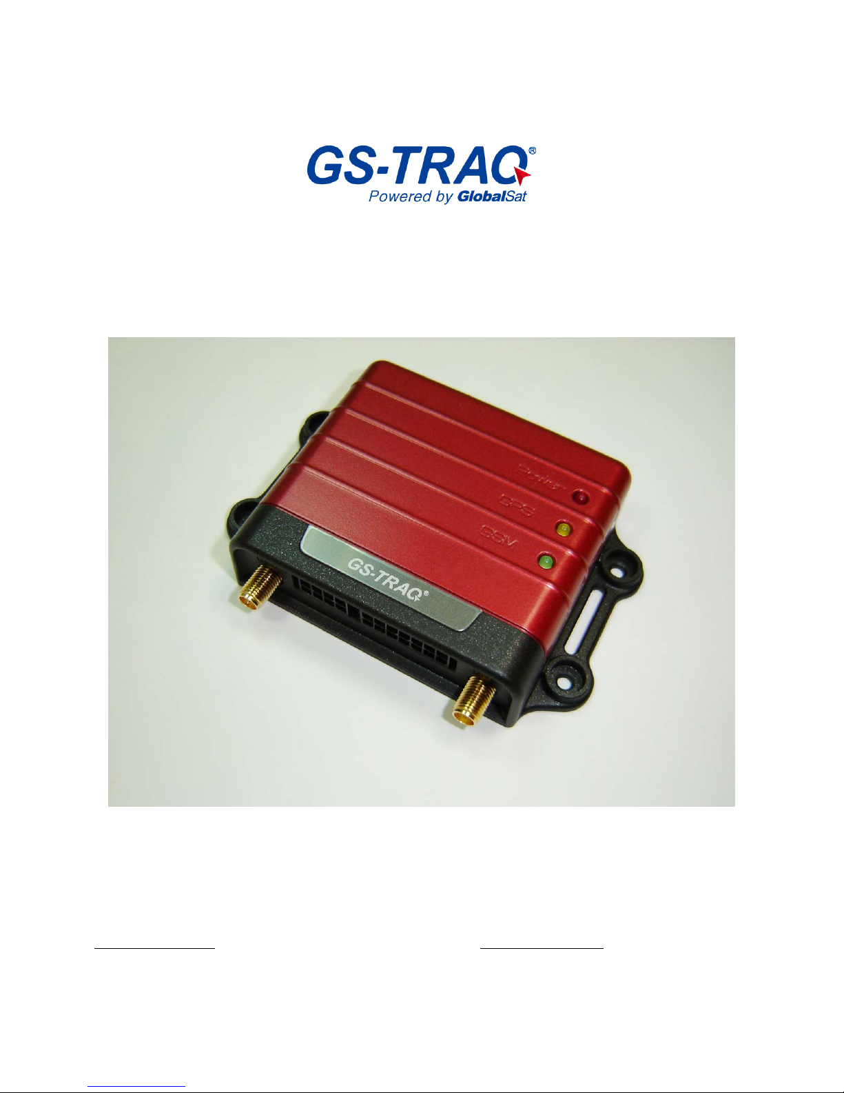
AVL Tracking System
TR-600
V 1.0
Globalsat Technology Corporation
16F., No. 186, Jian-Yi Road, Chung-Ho City , Taipei Hsien 235, Taiwan
Tel: 886.2.8226.3799/ Fax: 886.2.8226.3899
.tw
www.globalsat.com.tw
USGlobalSat Incorporated
1308 John Reed Court, City of Industry, CA 91745
Tel: 626.968.4145 / Fax: 626.968.4373
[email protected]
www.usglobalsat.com
Page 2

2
CONTENT
1. Introduction .......................................................................................................................................3
1.1 Introduction.............................................................................................................................3
1.2 Features....................................................................................................................................3
1.3 Hardware Architecture ........................................................................................................4
1.4 Hardware specification........................................................................................................5
1.5 Appearance..............................................................................................................................6
1.6 LED indicator...........................................................................................................................7
1.7 Cable description...................................................................................................................8
1.8 Accessories ............................................................................................................................10
2 Operation............................................................................................................................................11
2.1 Install the SIM card............................................................................................................11
2.2 Install the GPS and GSM antenna................................................................................12
3 Free Web Service.............................................................................................................................14
3.1 Preparation for Use Website............................................................................................14
3.2 Account creation..................................................................................................................14
3.3 Account creation..................................................................................................................18
3.4 Delete device from your account..................................................................................18
3.5 Set up SOS Parameters....................................................................................................19
3.6 Set up Digital Output.........................................................................................................20
3.7 TR-600 Motion report.........................................................................................................21
Page 3

3
1. Introduction
1.1 Introduction
The TR-600 is a multi-functional and economically feasible communication platform for mobile
positioning applications. It integrates highly sensitive GPS module and quad-band GSM
communication module with a powerful microcontroller that fits into a compact enclosure. The
TR-600 has a solid and rigid housing, for simple installation. It provides real-time GPS positions
anytime and anywhere with an open view to the sky, and offers precise positioning, and reports
vehicle status to the server with necessary information shown on the map. Benefits such as
enhanced fleet management, improved vehicle safety, emergency response, are all
accomplished through the implementation of the TR-600 system.
1.2 Features
y Build in Quad-band 850/900/1800/1900 MHz GSM system
y Build in high sensitivity GPS system
y Supports AT command via SMS/ TCP/UDP
y Remote control via SMS/GPRS command
y Real-time GPS position feedback and vehicle status monitoring
y Built-in in digital outputs (3), digital inputs (3), an ACC input, 1 analog input, and 1 serial
port
y Power supply for Li-ion battery and lead-acid battery
y Supports multi geo-fence function
y OTA (Over the air) firmware updates
y Data logger for 50,000 points
y Ignition/ Power Low/ Power Lost / Speed Limit detection alarm
y 3 LED indicators for GSM, GPS, power status
y External panic button for emergency SOS (Optional)
Page 4
4
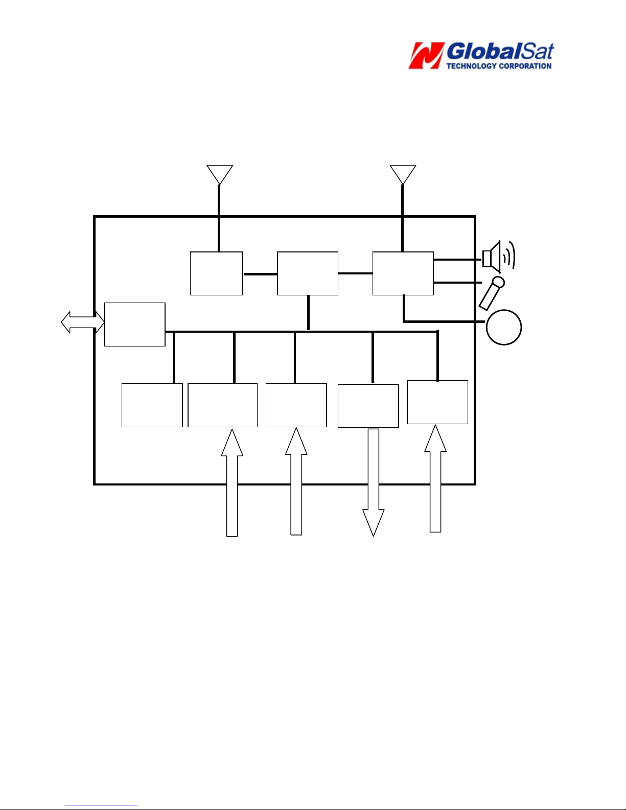
1.3 Hardware Architecture
GPS antenna GSM antenna
Speaker
Microphone
CPU
GPS
GSM
MODEM
Analog
Input
Digital
output
Digital
input
Li backup
Battery
USART/
RS-232
Motion
Sensor
SOS
Page 5
5
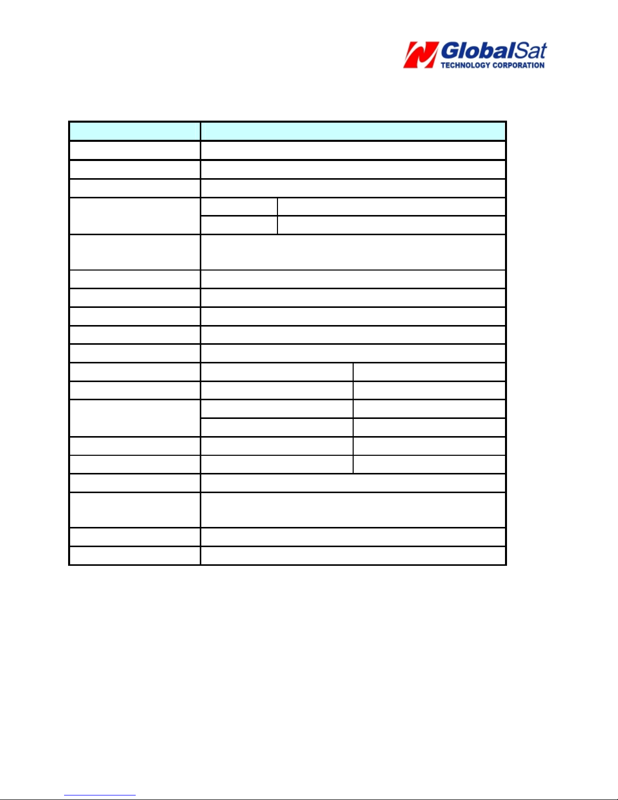
1.4 Hardware specification
Item Description
Dimension 98 mm X 65 mm X 22 mm
CPU High performance line ARM-base 32-bit MCU
GPS receiver SiRF Star III high performance GPS chipset
Operation
-30℃ ~ + 80℃
Temperature
Storage
-40℃ ~ + 85℃
GPS Antenna SMA T ype connector
Active antenna ( 3.3~3.8V)
GSM Antenna SMA T ype connector
Communication Telit (GE865) Quad-band GSM 850/900/1800/1900 MHz
Protocol Voice/SMS/GPRS (TCP/UDP)
Built-in Memory 32 Mb
GPS logging capacity 50,000 points
Emergency Input Negative trigger 1
Ignition (ACC) Input Positive trigger 1
Negative trigger 2 Digital Input Port
Positive trigger 1
Digital Output Port Negative trigger 3 (300 mA)
Analog Input Port Analog Input 1( 0~28V)
Serial Port 115200 bps
Backup battery (Option) Internal 800 mAh Lion battery
Support external Lead-acid battery (12V/24V)
Hands-free Kit (Option) Support external speaker and microphone
Sensor Motion sensor
Page 6
6
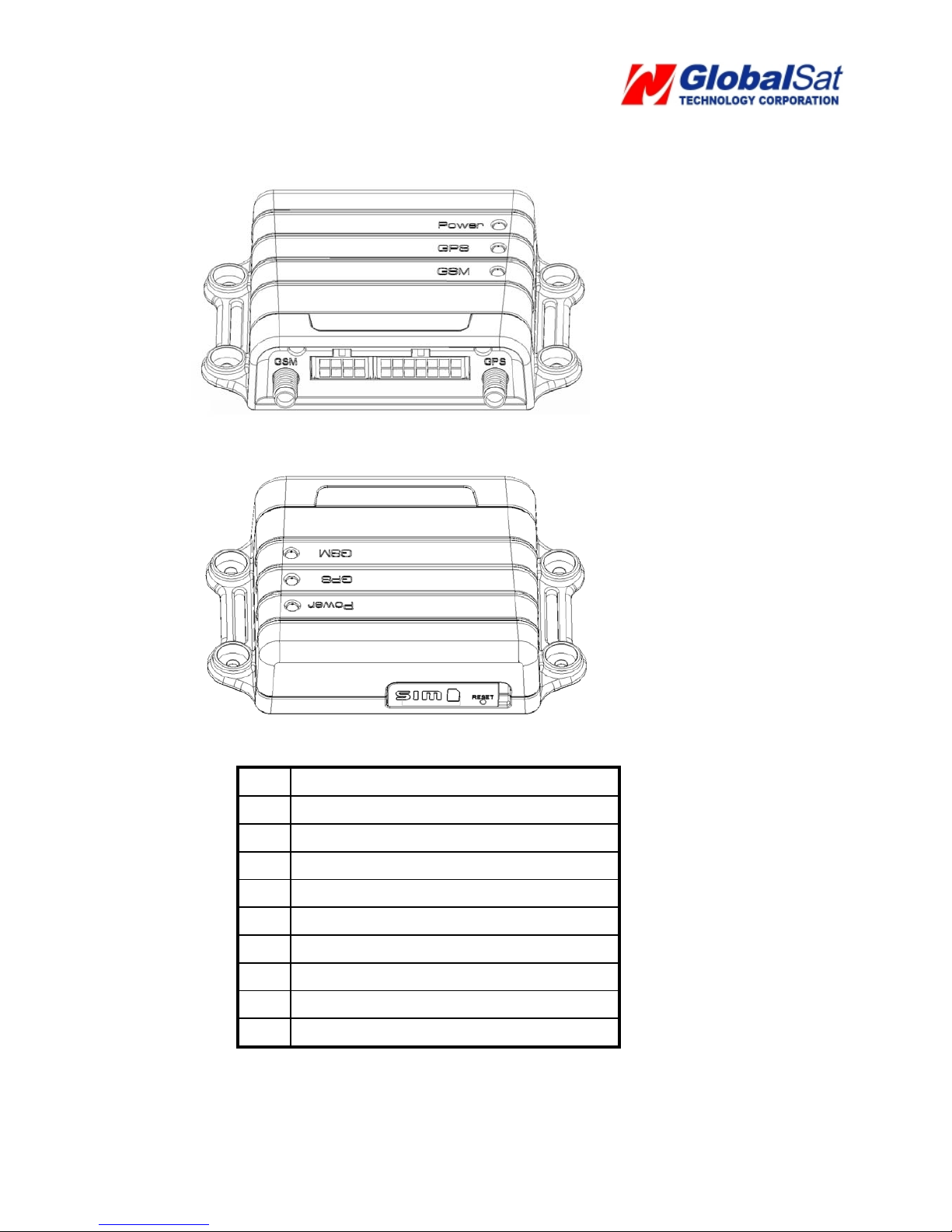
1.5 Appearance
1 Peripheral interface port
2 I/O port
3 Power Status LED
4 GPS LED
5 GSM LED
6 For fixing device with screws
7 GSM antenna connector
8 For fixing device with belt
9 GPS antenna connector
10 SIM card holder
1 2
3
4
5
6 6
7
8
9
10
8
6
6
Page 7
7
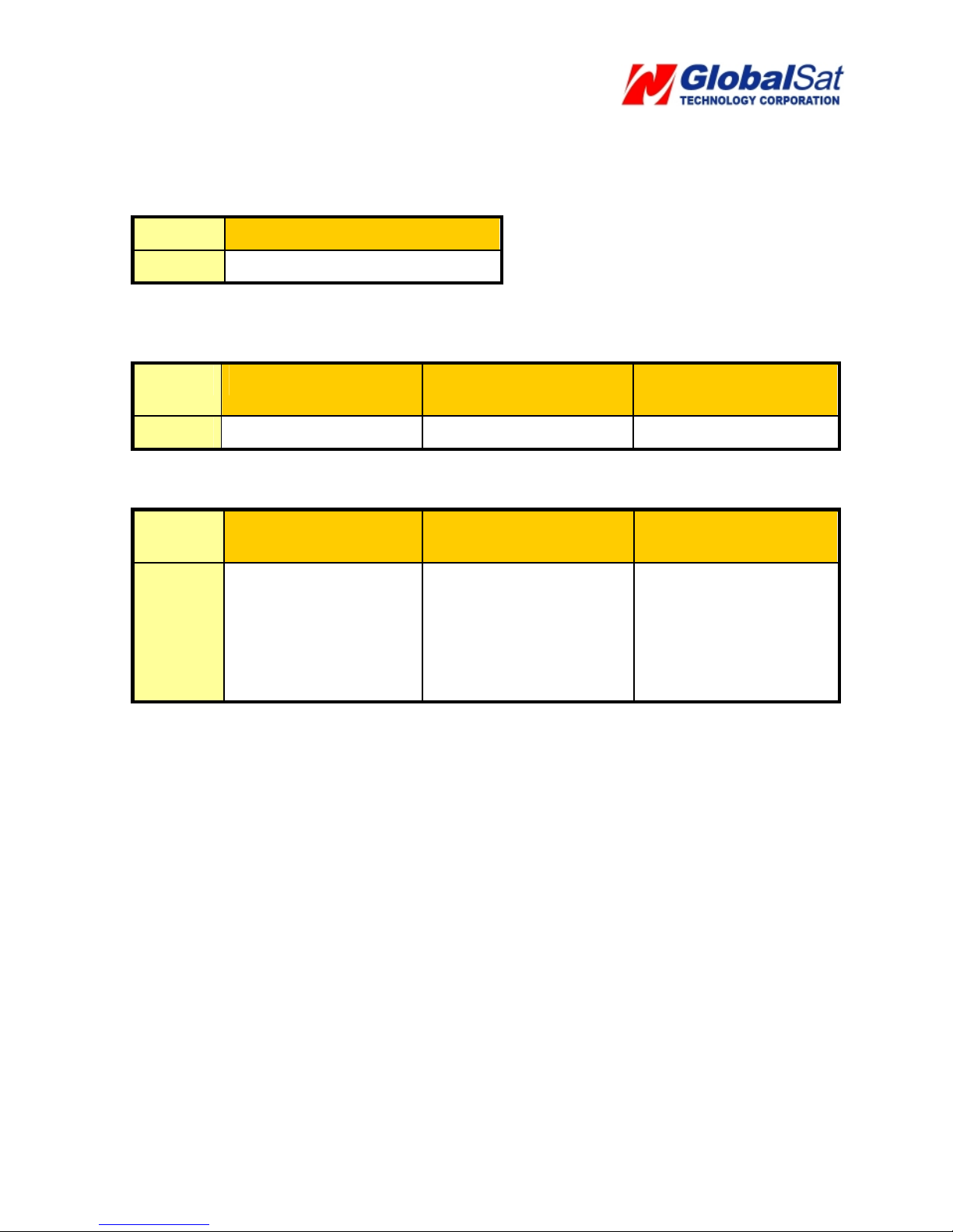
1.6 LED indicator
Power Status LED (Red)
LED Permanently On
State Main power on, device on
GPS LED (Yellow)
LED Permanently off Fast blinking (Once
every 1 second)
Slow blinking (Once
every 3 seconds)
State GPS off GPS not fix GPS fix
GSM LED (Green)
LED Permanently off Fast blinking (Once
every 1 second)
Slow blinking (Once
every 3 seconds)
State GSM off 1. TR-600 is
searching GSM
network
2. SIM card is
registering to GSM
network
TR-600 is registered
full service
Page 8
8
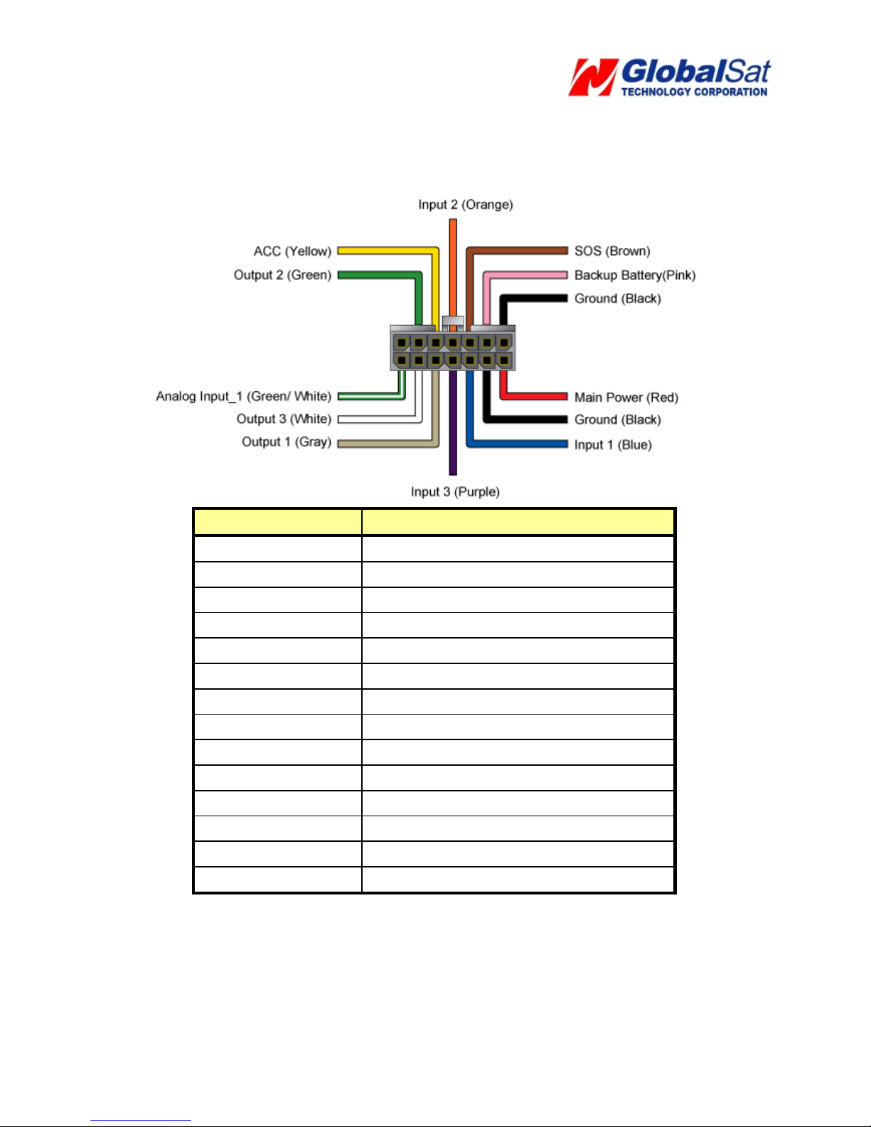
1.7 Cable description
14 Pin I/O Cable
Wire Color Description
Green/ White
Analog Input_1
White
Digital Output 3 (Negative Trigger)
Gray
Digital Output 1 (Negative Trigger)
Purple
Digital Input 3 (Positive T rigger)
Blue
Digital Input 1 (Negative T rigger)
Black
Ground
Red
Main Power
X
Green
Digital Output 2 (Negative Trigger)
Yellow
ACC (Positive Trigger)
Orange
Digital Input 2 (Negative T rigger)
Brown
SOS (Negative Trigger)
Pink
12V/24V Backup Battery
Black
Ground
Page 9
9
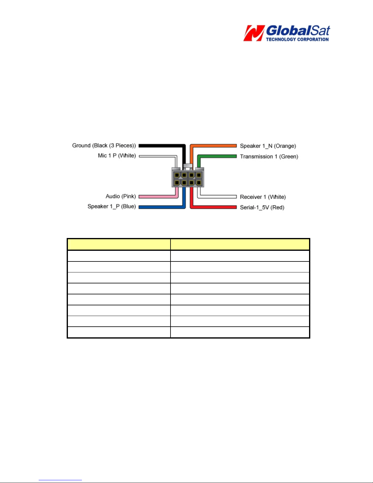
8 Pin Cable
Wire Color Description
Pink Audio_5V
Blue Speaker 1(Positive)
Red Serial-1_5V
White Receiver 1
White Microphone 1 P
Black (3 Pieces) Ground
Orange Speaker 1(Negative)
Green Transmission 1
Page 10
10
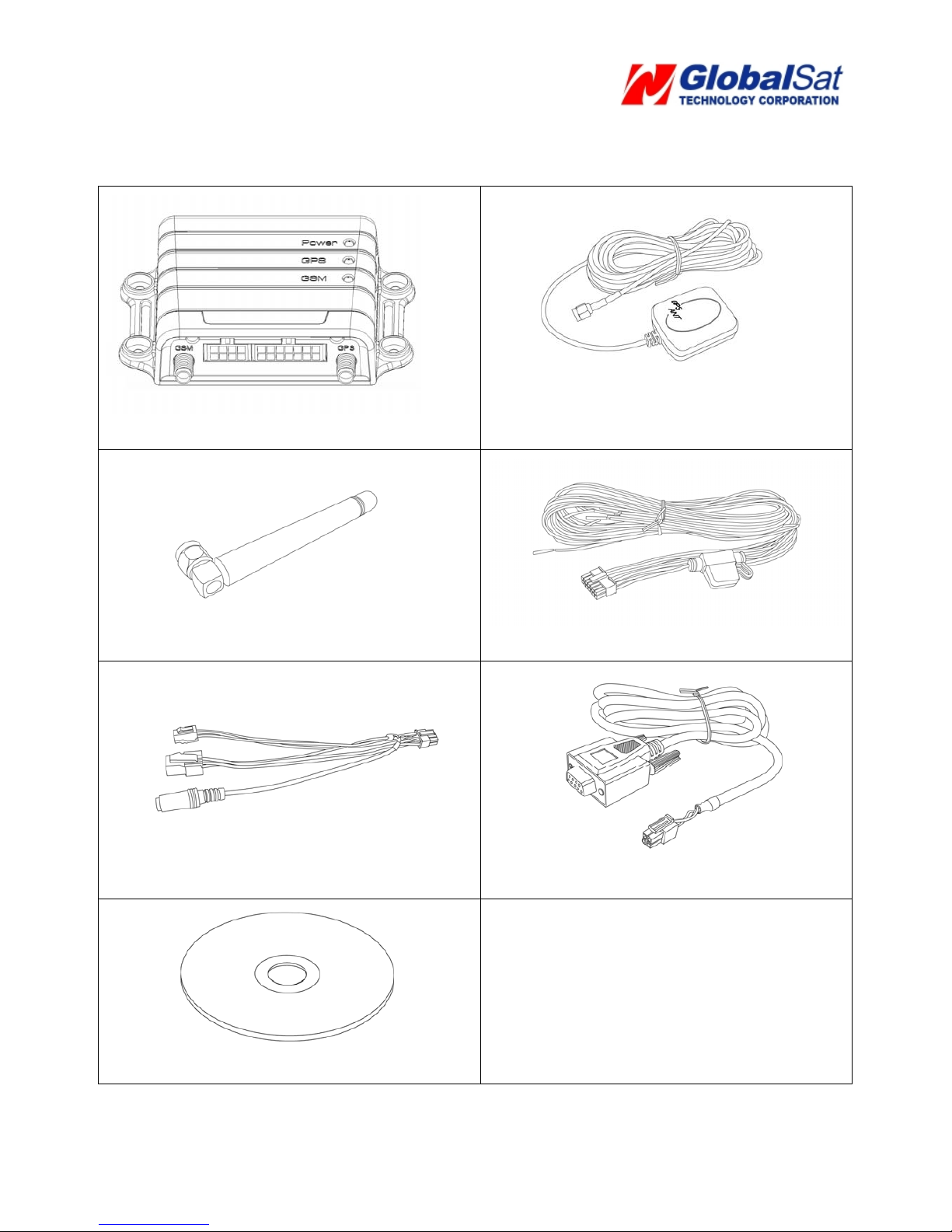
1.8 Accessories
Main Unit
GPS Antenna
GSM Antenna 14 Pin I/O Cable
8 Pin Cable
RS-232 Cable (Option)
CD (User manual, driver)
Page 11
11
2 Operation
For first time users, please follow the steps below to complete the pre-installation.
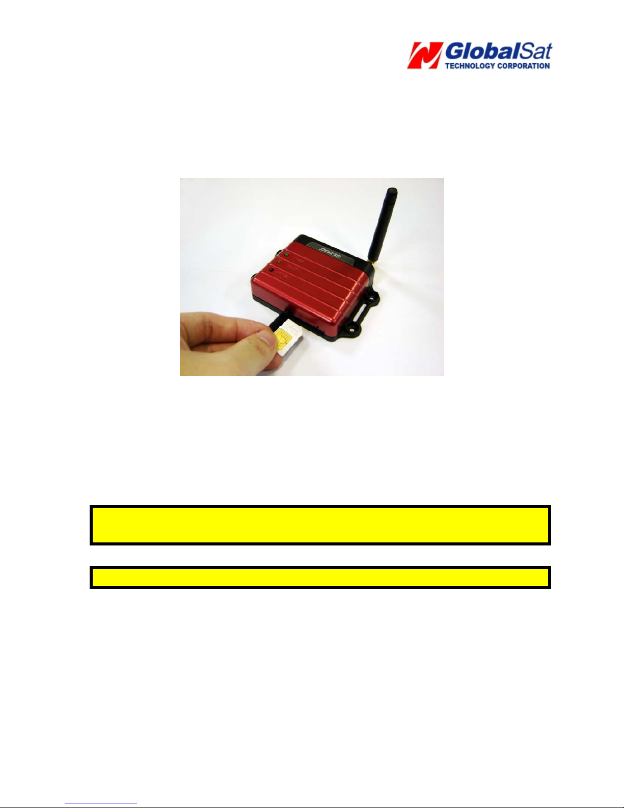
2.1 Install the SIM card
With the cooper contacts face-up, align the notch on the SIM card with the notch on the
SIM slot and insert the SIM card. If SIM is inserted correctly, you will not be able to see the
copper contacts after inserting the card. To eject SIM card, simply, use your finger nail and
apply slight pressure.
Note: Make sure to disable the SIM PIN entry function on the SIM card before inserting
your SIM card
Note: Before installing or taking out the SIM card, please power off the TR-600.
Page 12
12
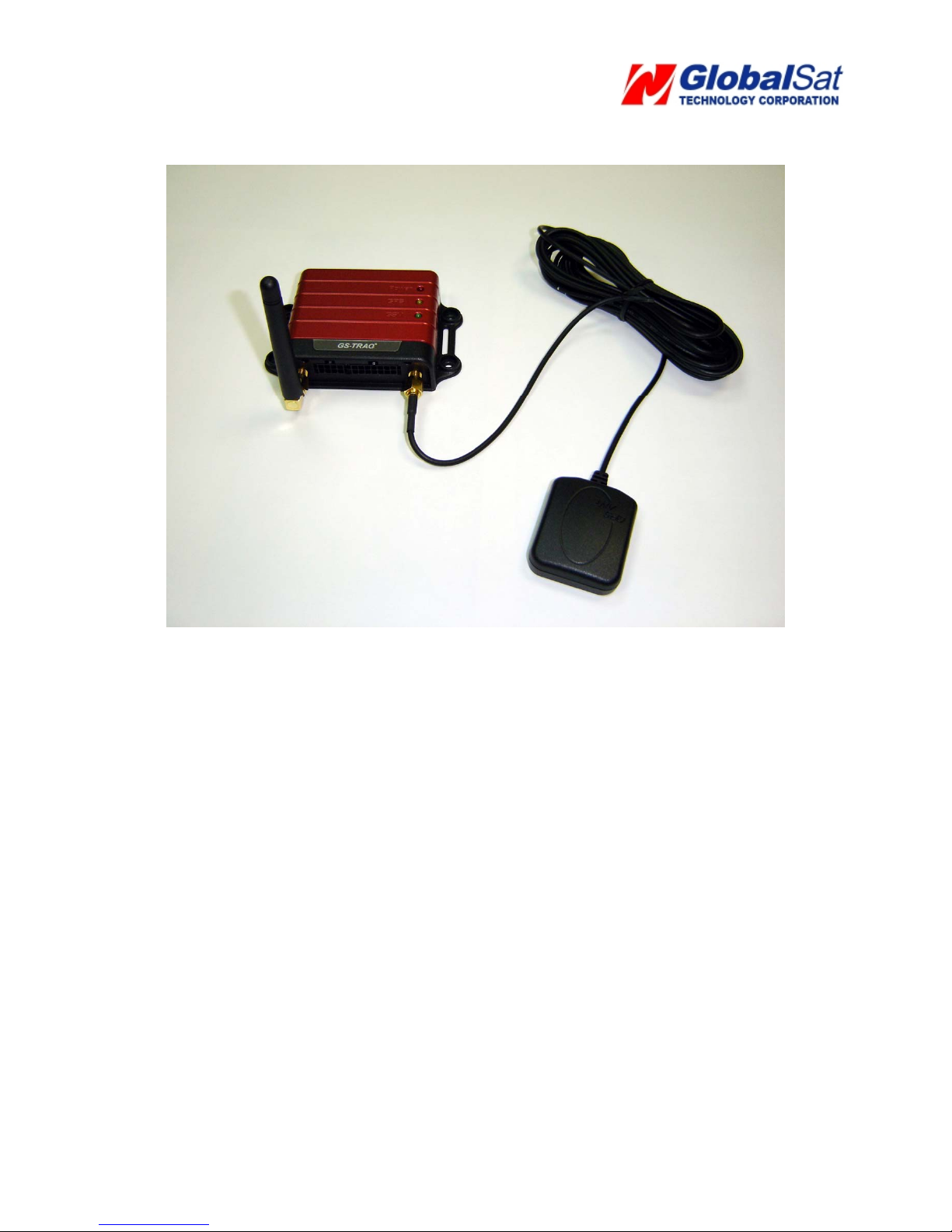
2.2 Install the GPS and GSM antenna
Install the GSM antenna to the GSM antenna port on the left side of the back of the
device and install the GPS antenna to the GPS antenna port on the right side of the
back of the device making sure both antennas tightly screwed in place. Please refer to
the photo above.
Page 13
13
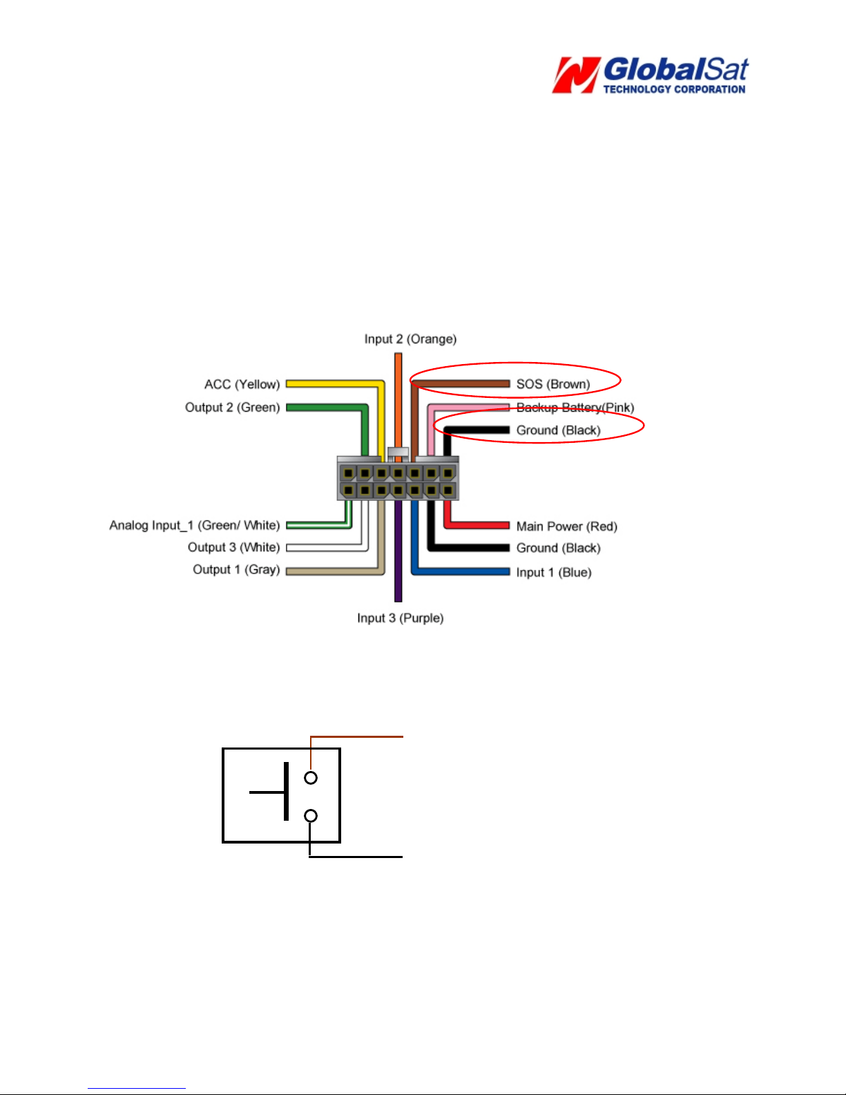
2.3 Installing the Emergency button
There is a line of the 14 pin IO cable for connecting push button for emergency help.
One end of the button must be connected to the SOS line and the other end must be connected
to the ground line.
SOS line
Ground line
Page 14
14
3 Free Web Service
3.1 Preparation for Internet Use
• Be certain your SIM card has an appropriate data plan whether it is a pre paid plan or a
month-to-month plan and verify with your telecommunications operator that your data
plan has GPRS activated. Or, you may verify GPRS connectivity by inserting your SIM
card into a mobile phone, and then test the GPRS by using the mobile phones web
browser.
• Contact your telecommunications operator concerning GPRS settings.
• Contact your telecommunications operator to disable voicemail, call waiting, and call
forwarding to the SIM card.
• The tracker IMEI and serial number information can be found on the bottom of the
TR-600.
3.2 Account creation
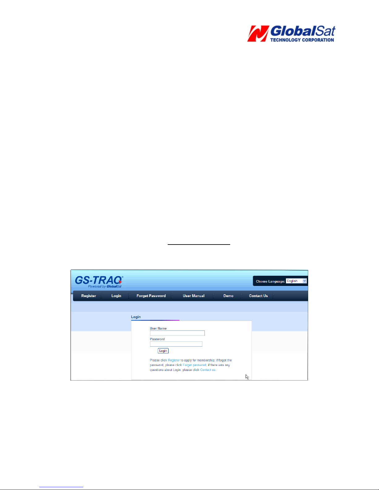
On your web browser please go to http://traq.gstraq.com/
Next, click the blue Register
link.
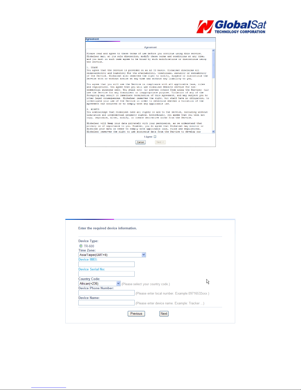
Read Agreement, check I Agree, and click Next button.
Page 15
15
Click the Next button.
Select your Time Zone, enter Device IMEI and Serial No., select your Country code, enter
Device Phone Number, Device Name, and click the Next button.
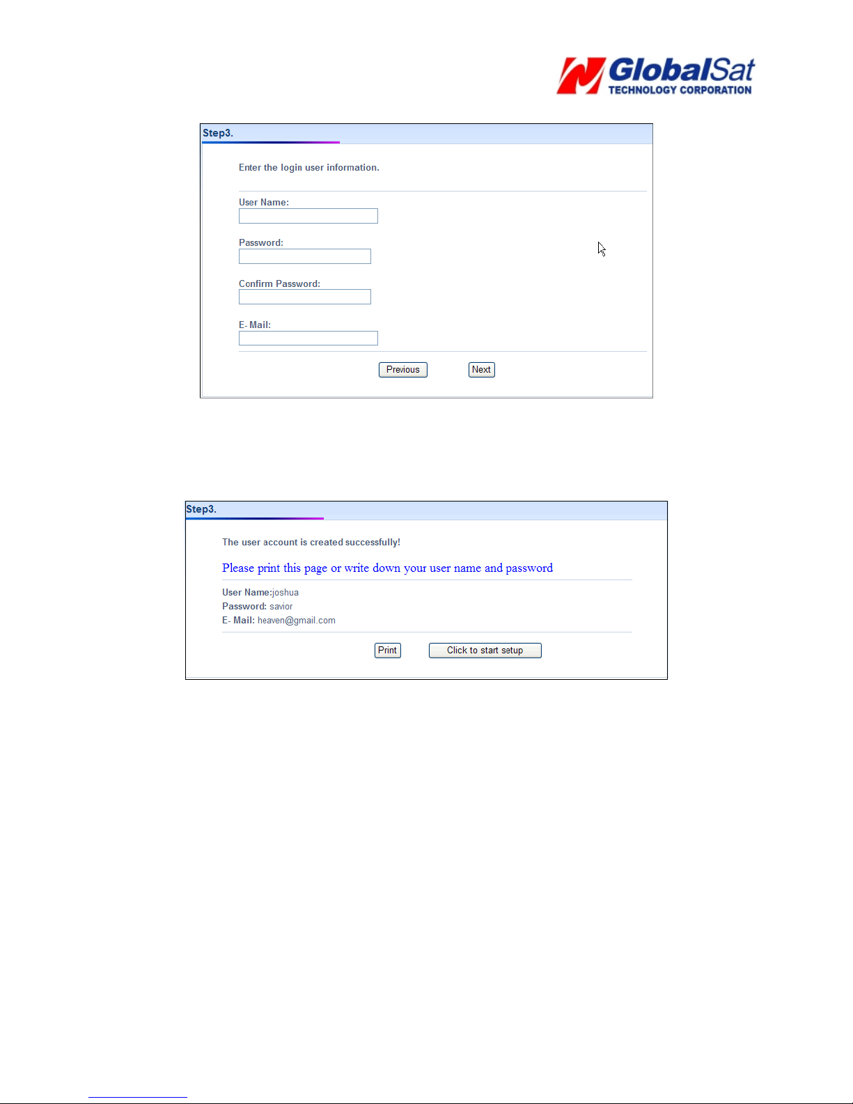
Create your login profile by entering User Name, Password, and Email, and click the Next
button.
Page 16
16
Please print this page or write down your User Name, Password and click “Click to start
Setup” button.
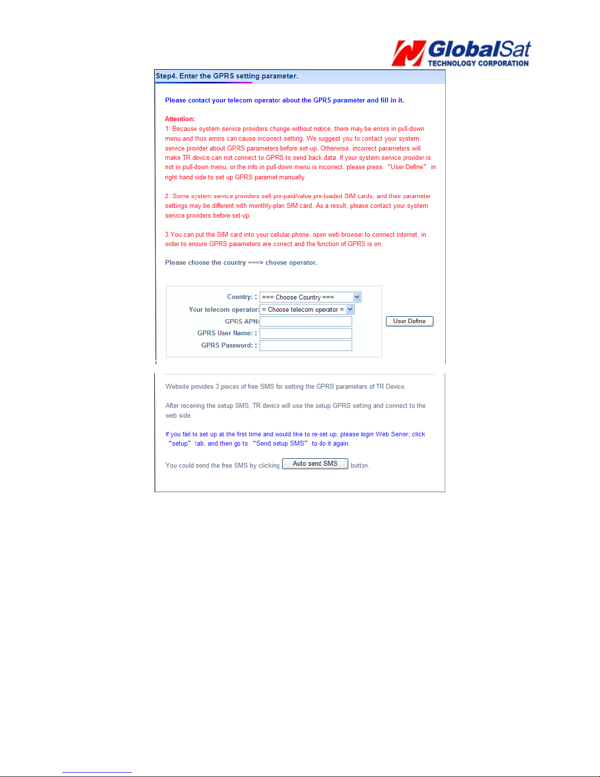
Select your country and telecommunications operator. Selecting your telecommunications
operator will bring out the concerning GPRS parameters. If you do not find your
telecommunications operator in the pull-down menu or the information in the pull-down
menu is incorrect, please click the User Define. And then please contact your
telecommunications operator about the GPRS parameter. Click the Auto Send SMS
button.
Page 17
17
Click the Send button.
Page 18
18
3.3 Account creation
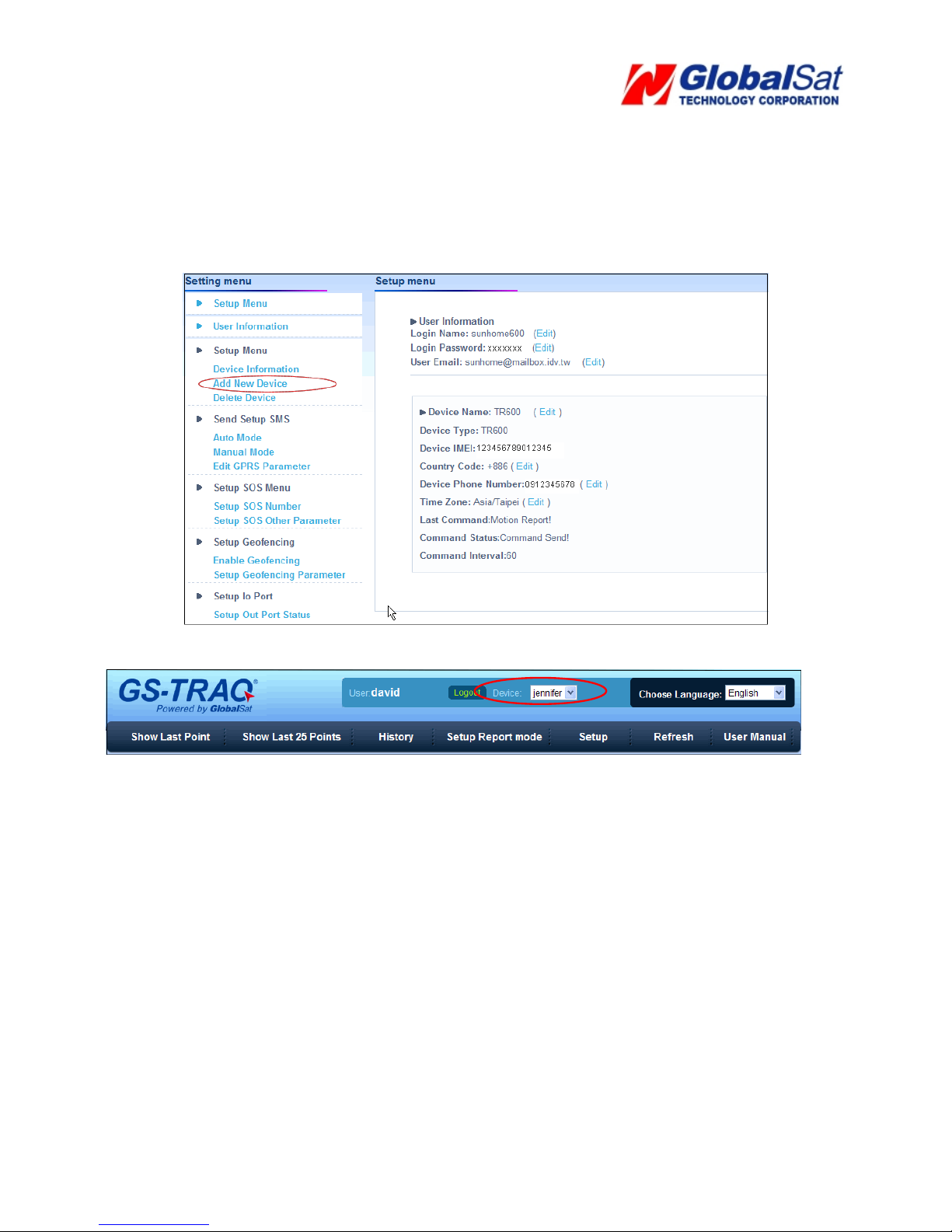
Perform the following: Setup Æ Add New Device
Then refer to 3.2 Create Account to enter the information of the device.
After adding the required information and sending out the SMS, you could switch to a different device by
selecting the Device pull-down menu on the upper right corner of the webpage.
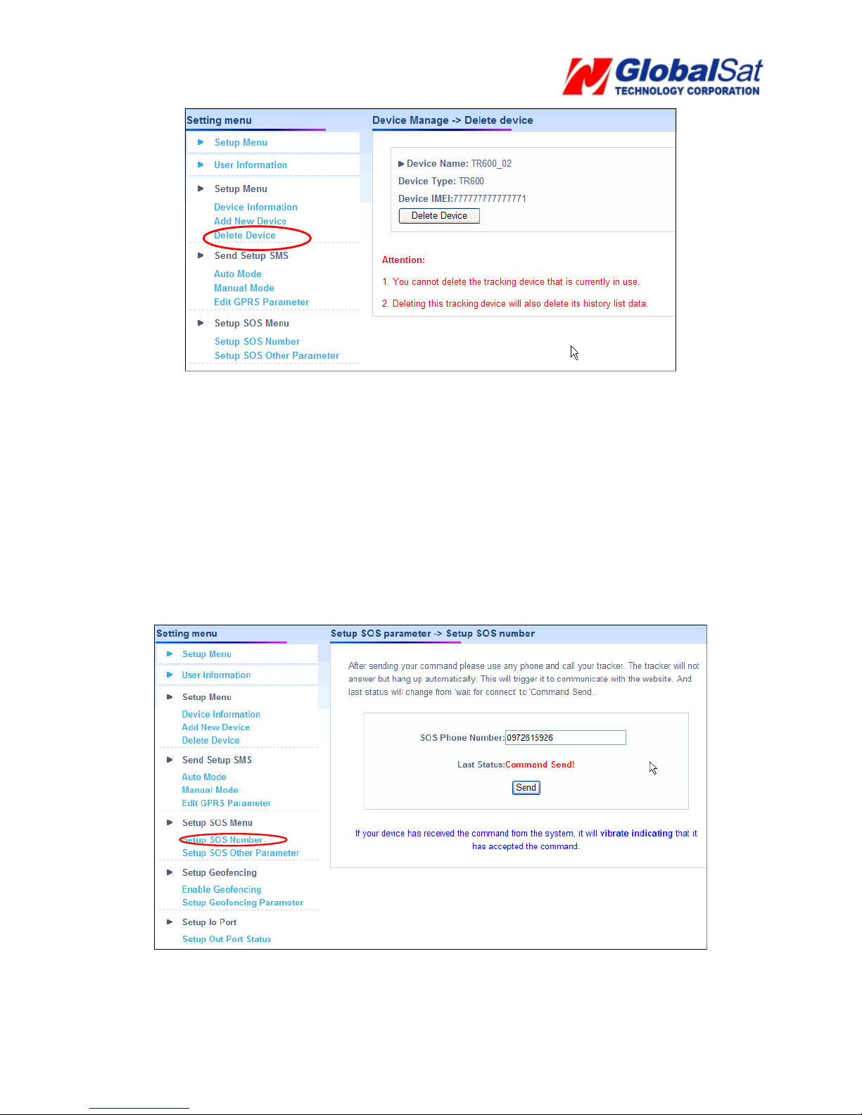
3.4 Delete device from your account
Perform the following: Go to Setup Æ Delete Device select the device you would like to delete. And then
click the Delete Device button.
Page 19
19
3.5 Setting up the SOS Parameters
SOS Phone Number
1. Perform the following: Setup Æ Setup SOS Number
2. Enter destination phone number to receive emergency SMS’.
3. Click the Send button.
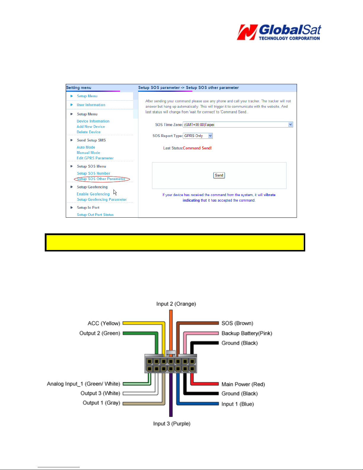
4. Next, go to the Setup SOS Other Parameter
SOS Time Zone
Page 20
20
1. Select your time zone for the SOS Time Zone and select your SOS Report Type
2. Click the Send button.
3. Then copy the SMS and send it to the phone number of the SIM card in your TR-600 via
mobile phone.
Note: .The content of the SOS report includes GPS fix date and time. The GPS date and time
will be according to the setting of SOS Time Zone.
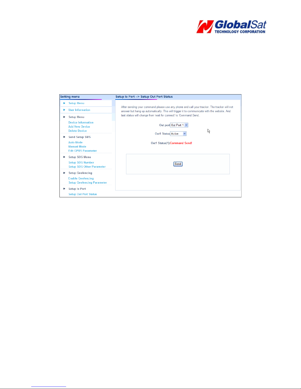
3.6 Set up Digital Output
There are 3 digital outputs of TR-600. Below please find the corresponding positions. You could
activate or deactivate on the GS-TRAQ website..
Page 21
21
1. Perform the following: Setup Æ Setup Out Port Status
2. Select digital output port in the pull-down menu of Out port.
3. Select Active to activate that digital output or Disactive, to deactivate that digital output in
the pull-down menu of Out Status.
4. Click the Send button.
5. Then please copy the SMS and send it to the phone number of TR-600 via mobile phone
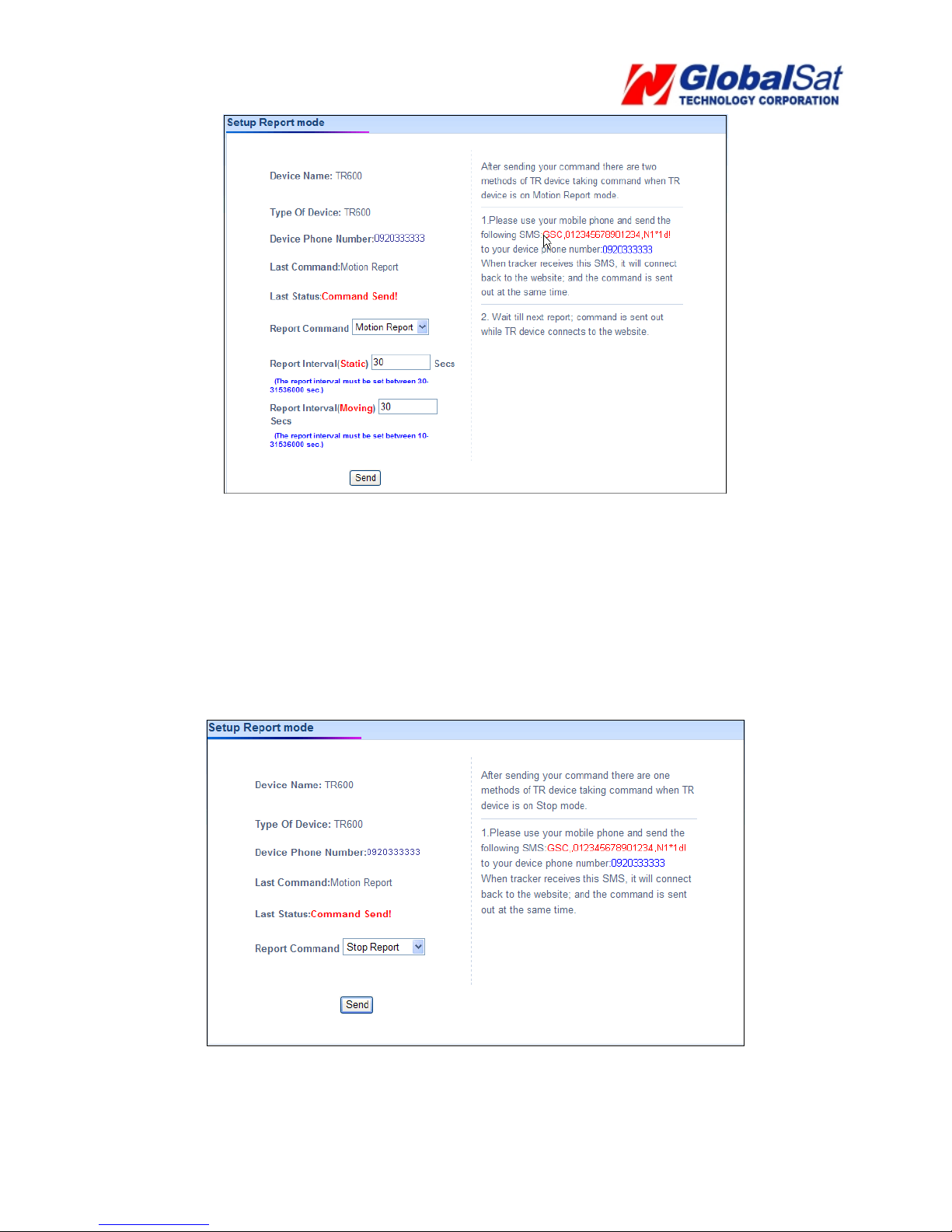
3.7 TR-600 Motion report
1. Select Setup Report Mode on the menu bar.
2. Select Motion Report in the pull-down menu of Report Command
3. Enter the value for Report Interval (Static) (Range 30~65535 seconds) and Report
Interval (Moving). (Range 10~65535 seconds)
4. Click the Send button.
5. Then please copy the SMS and send it to the phone number of TR-600 via mobile
phone
Page 22
22
3.8 Stop TR-600 Motion report
Stop Motion Reporting
1. Select Setup Report Mode on the menu bar.
2. Select Stop Report in the pull-down menu of Report Command
3. Click the Send button. The TR-600 will stop the motion report.
4.
Copy the SMS and send it to the phone number of TR-600 via mobile phone.
Page 23
23
3.9 TR-600 Geo-fence Function
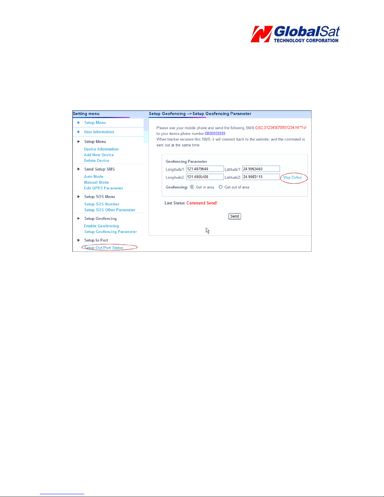
Setup Geo-fence area
1. Select Setup on the menu bar.
2. Select Setup Geo-fencing Parameter.
3. Click on Map Define
Page 24
24
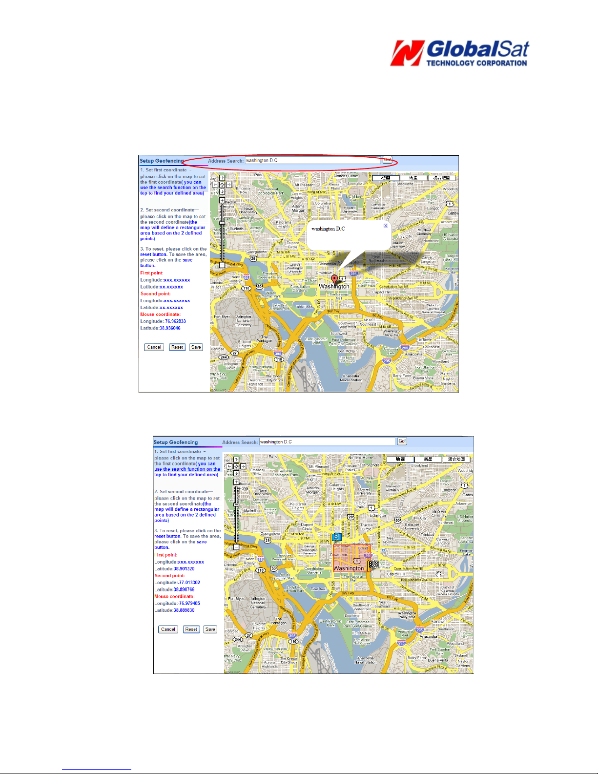
4. You can then enter a specific address or city or landmark in the Address Search field and
then click the Go button. The map will move to the entered location. For example, the map
will show as below after entering Washington D.C.
5. Move the cursor and click on the two points of the map to form a geo-fence area like the
screenshot below.
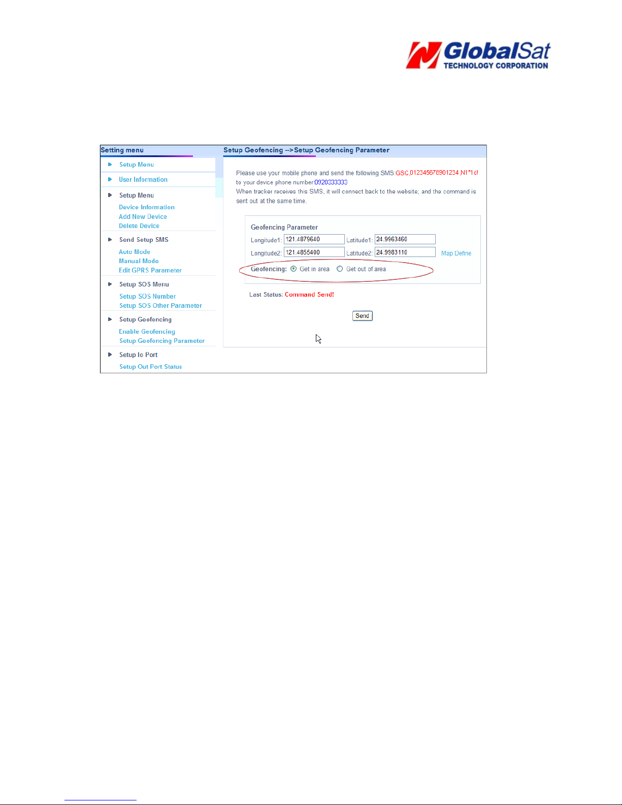
6. Click the Save button to save the area. If you want to reset the area, click on the Reset
Page 25
25
button to reset the area.
7. After clicking the Save button, select if you want to receive the geo-fence alarm report when
the TR-600 travels in the geo-fence area or travels out of the geo-fence area.
8. Click the Send button to send out the setting.
9.
Copy the SMS and send it to the phone number of TR-600 via mobile phone. It will
make the TR-600 connect to the website to get the settings.
The steps above are for setting geo-fence area. You have to enable the geo-fence
function by following the steps below.
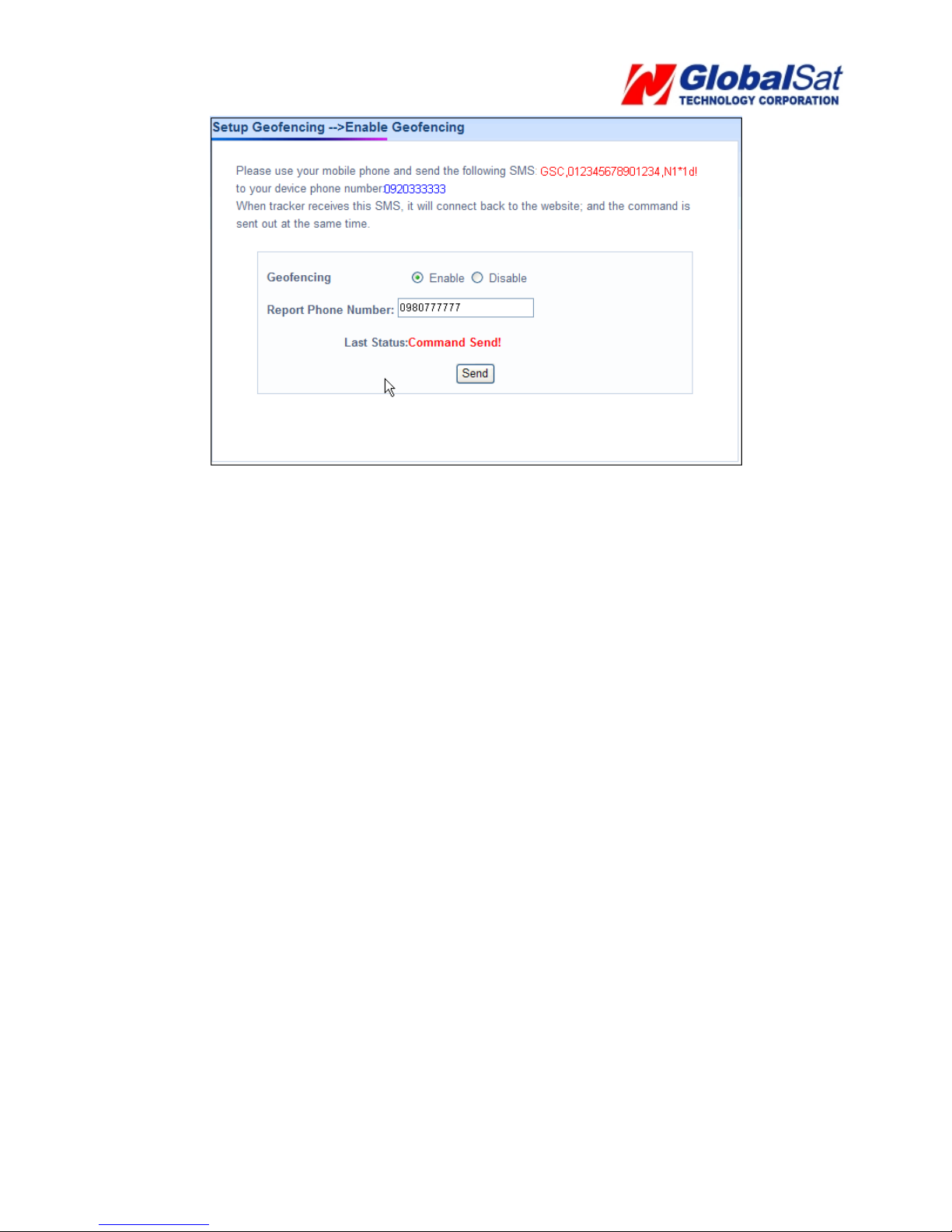
Enable Geo-fence function
1. Select Setup Æ Enable Geo-fencing
2. Click Enable
3. Enter the mobile phone number for receiving the geo-fence alarm report in the field of
Geo-fencing Phone Number.
Page 26
26
4. Click the Send button to send out the setting.
5. Please copy the SMS and send it to the phone number of TR-600 via your mobile
phone. It will make the TR-600 connect to the website to retrieve the geo-fence
command.
 Loading...