

Page 1

GSTOP® LITE
WWW.GSTOP.CO.UK
Designed in Great Britain
Version 1.1
Page 2

GSTOP® LITE Overview
GSTOP® LITE - Smart Brake Force Sensing Safety Device for Cars,
Motorbikes, Vans and other road vehicles.
GSTOP® LITE is a factory pre-set retrofit ELBD System. ELBD means
‘Emergency Brake Light Display’ as detailed in UNECE European
Regulations for road vehicles.
GSTOP® LITE does not interfere with normal brake light operation,
GSTOP® LITE only activates under heavy sustained braking in excess
of the preset g-force values of 0.6g and 0.8g. For comparison,
Gravity (the mysterious force that holds everything on the ground) is
1.0g
Page 3

GSTOP® LITE utilises a high speed digital accelerometer to
accurately measure deceleration when braking. ‘Error Correction’
(Smoothing ;-) is applied to the accelerometer data to correct for
inconsistent feedback commonly caused by but not limited to; Road
noise, Uneven road surface, Vibration etc.
GSTOP® LITE is factory pre-set and does not facilitate user
configuration. (For the ability to tune GSTOP® see; GSTOP® PRO)
What’s in your GSTOP® box
• 1x GSTOP® LITE
• 3x Wire Connectors (2x 2-way 1x 3-way Crimp Type)
• 1x Universal Wiring Loom
• 1x Bench Test Wiring Loom (requires 9v battery - not included)
• 1x Foam Mounting Pad
Page 4
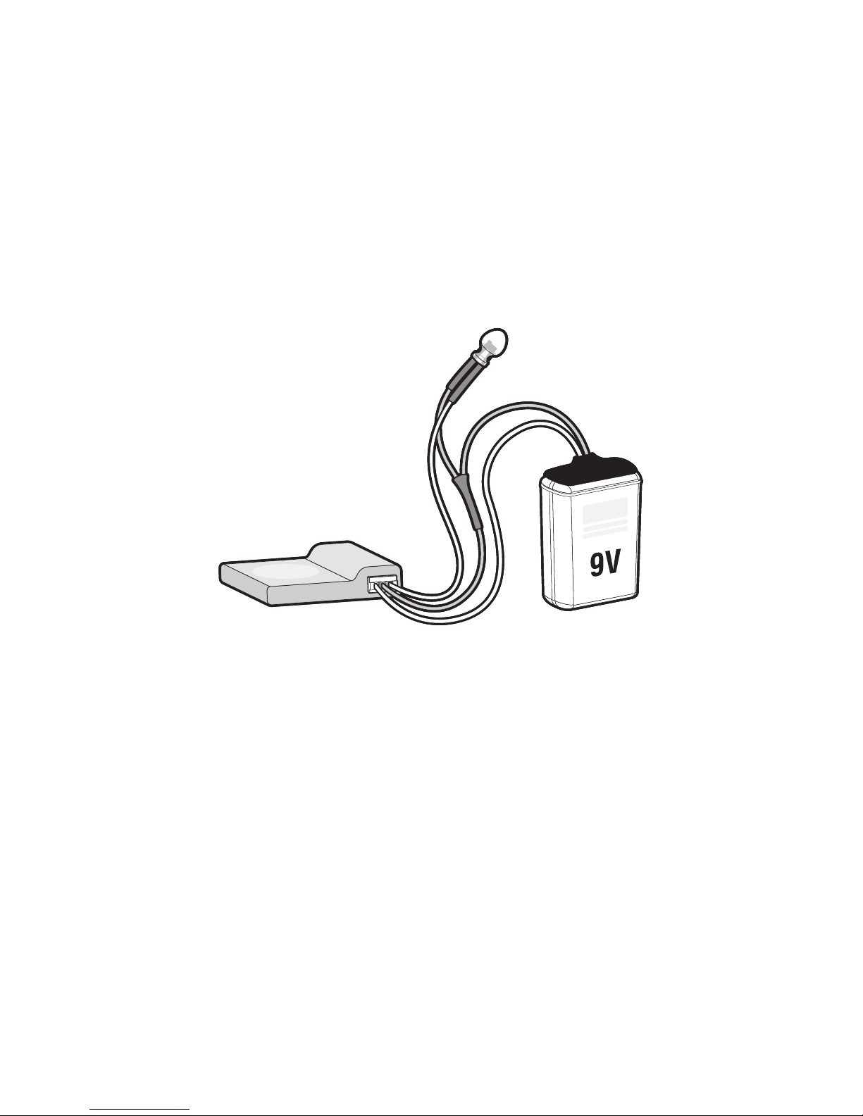
Your GSTOP® LITE device comes with a ‘Bench-Test’ wiring loom. You
can use this to power up and test how your GSTOP® works before
installation. Connecting a 9v battery (PP3) to the battery connector
simulates how GSTOP® powers up when the vehicles brake lights are
switched on.
GSTOP® Bench-Test
Wiring Loom
Page 5

Operation and Features
• GSTOP® is inactive when vehicle is stationary
• Activation is triggered automatically by heavy sustained braking
• Activation is deactivated automatically when braking force is no
longer present
• Dual Stage Inertia Activation
• Does not interfere with vehicle bulb condition monitor
• Does not interfere with normal braking conditions
• FailSafe Design - in case of ‘GSTOP®’ failure.. the Vehicle Stop
• Light continues to function normally
• Accelerometer Smoothing ;-)
Page 6

Factory Configuration
Your GSTOP® LITE device is factory pre-programmed to operate with
the following settings:
• Axis: X+ (see Direction Arrow on GSTOP® LITE device)
• Trigger.1: 0.6g / @2Hz / 2.0 Seconds
• Trigger.2: 0.8g / @3Hz / 3.0 Seconds
• Duty Cycle: 50% on / 50% o
• Error Correction: Enabled (Smoothing; prevents nuisance activation)
(GSTOP® LITE does not support user-configurable options. For user
tuning settings, please see GSTOP® PRO)
Page 7

Wiring Installation
Please Note: You should be competent in automotive wiring before
attempting to install the GSTOP® LITE Module. If in doubt, please
seek the assistance of a trained professional.
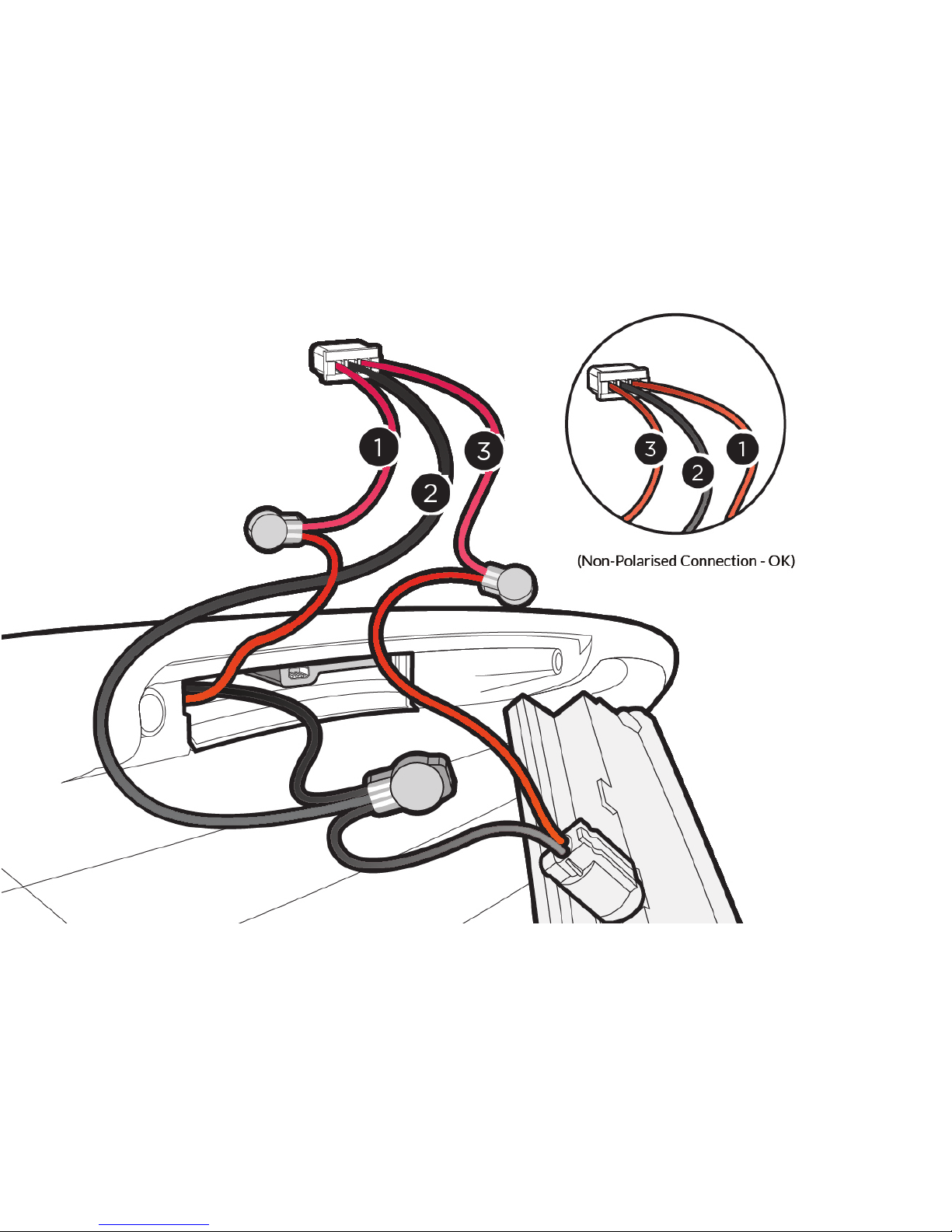
GSTOP® is shipped with a 3-wire universal wiring loom.
The centre Black wire (Terminal.2) must be connected to Vehicle
ground / 0v. The two Red wires (interrupt relay) must be connected
to the positive wire that goes to the vehicles High Level Brake Light.
Terminals 1. and 3. are non-polarised, and can be connected in either
direction.
Please see the attached wiring diagrams:
Page 8
Page 9

Installation (Location Fitment)
GSTOP® LITE is shipped in a Factory Pre-Set to operate on Axis ‘X+’
Take care to observe the correct axis when fitting the GSTOP®
LITE Module. Please note, GSTOP® LITE should be installed on a
’level plane’ (to ensure the digital accelerometer accuracy) Tilting
GSTOP® LITE forwards will reduce the ‘braking force’ required to
trigger the EBLD Warning Flash Sequence, this is due to gravity
exerting a combined eect on the forward axis. (Please note; EBLD
Brake Warning Signalling should not be used under normal braking
conditions in order to comply with EU/UK Regulation)
Secure GSTOP® LITE in place using Sticky Foam Pad(s) included.
Page 10
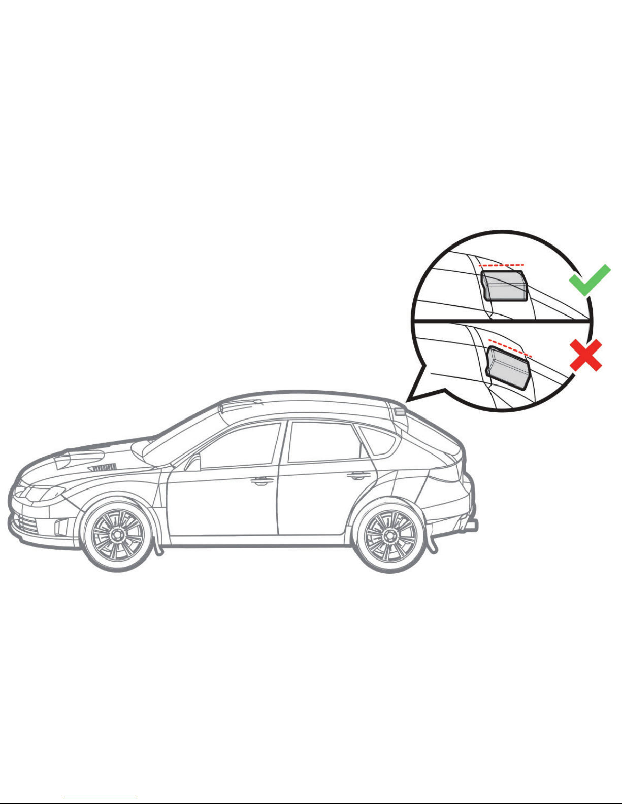
Installation Orientation
Page 11
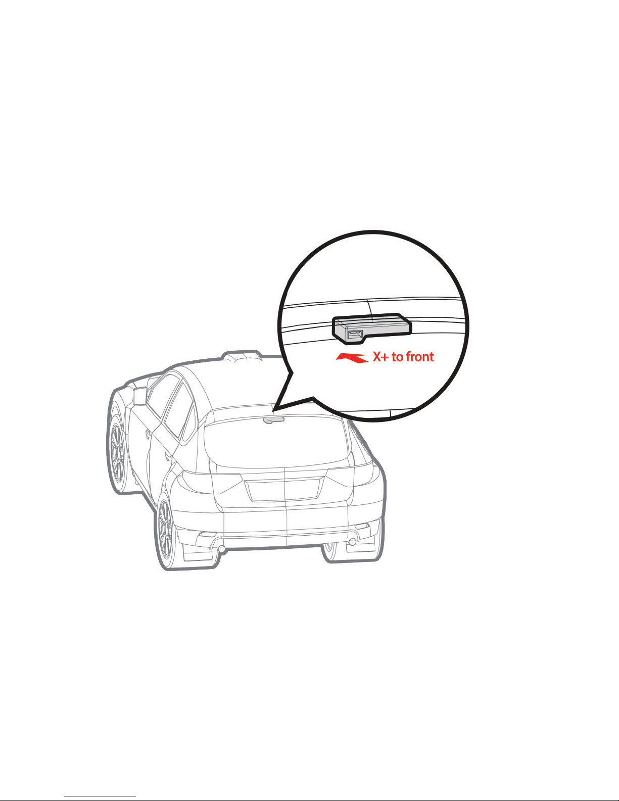
X-axis Primary
(Typical Install for Car Roof
Lining)
Installation Orientation
Page 12
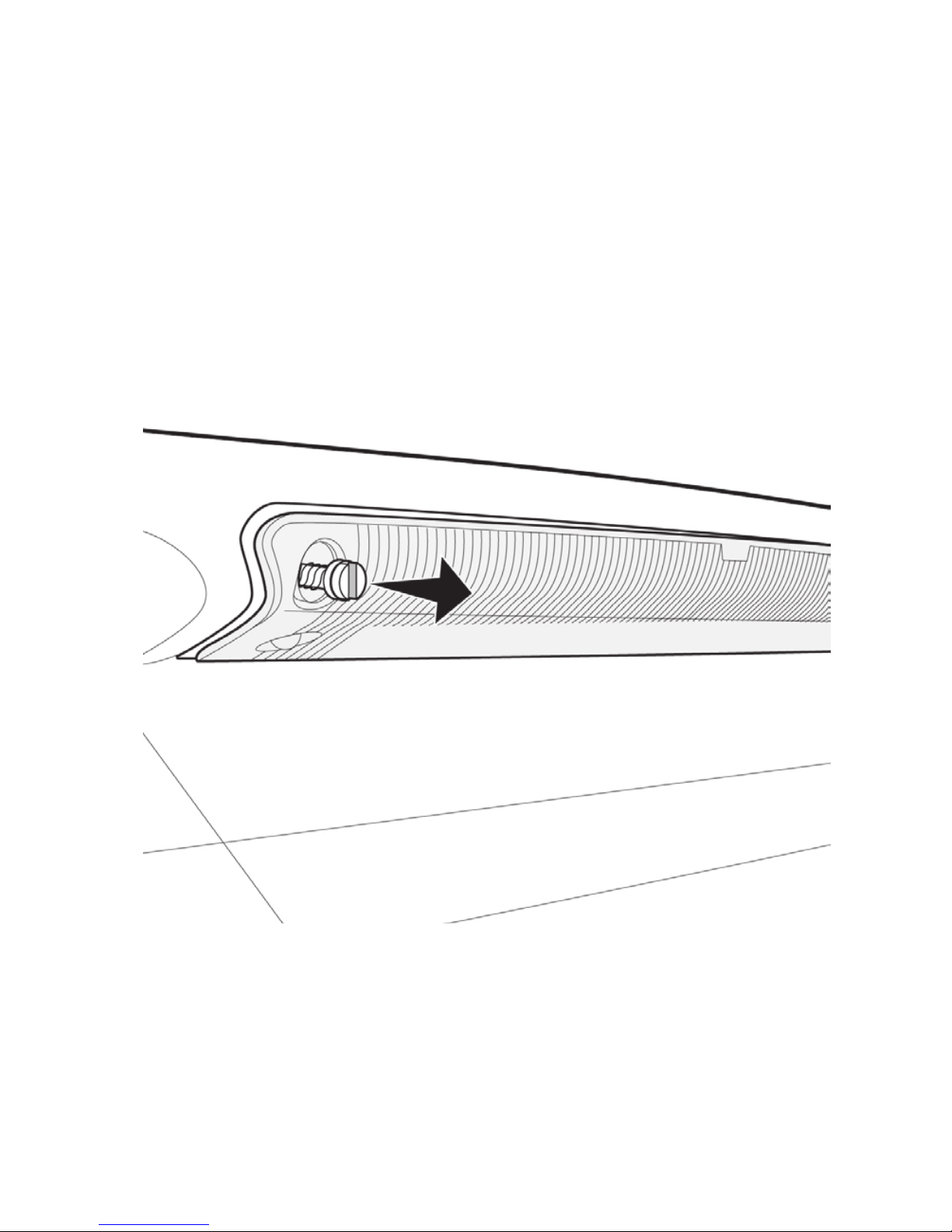
Brake Light Removal
Page 13
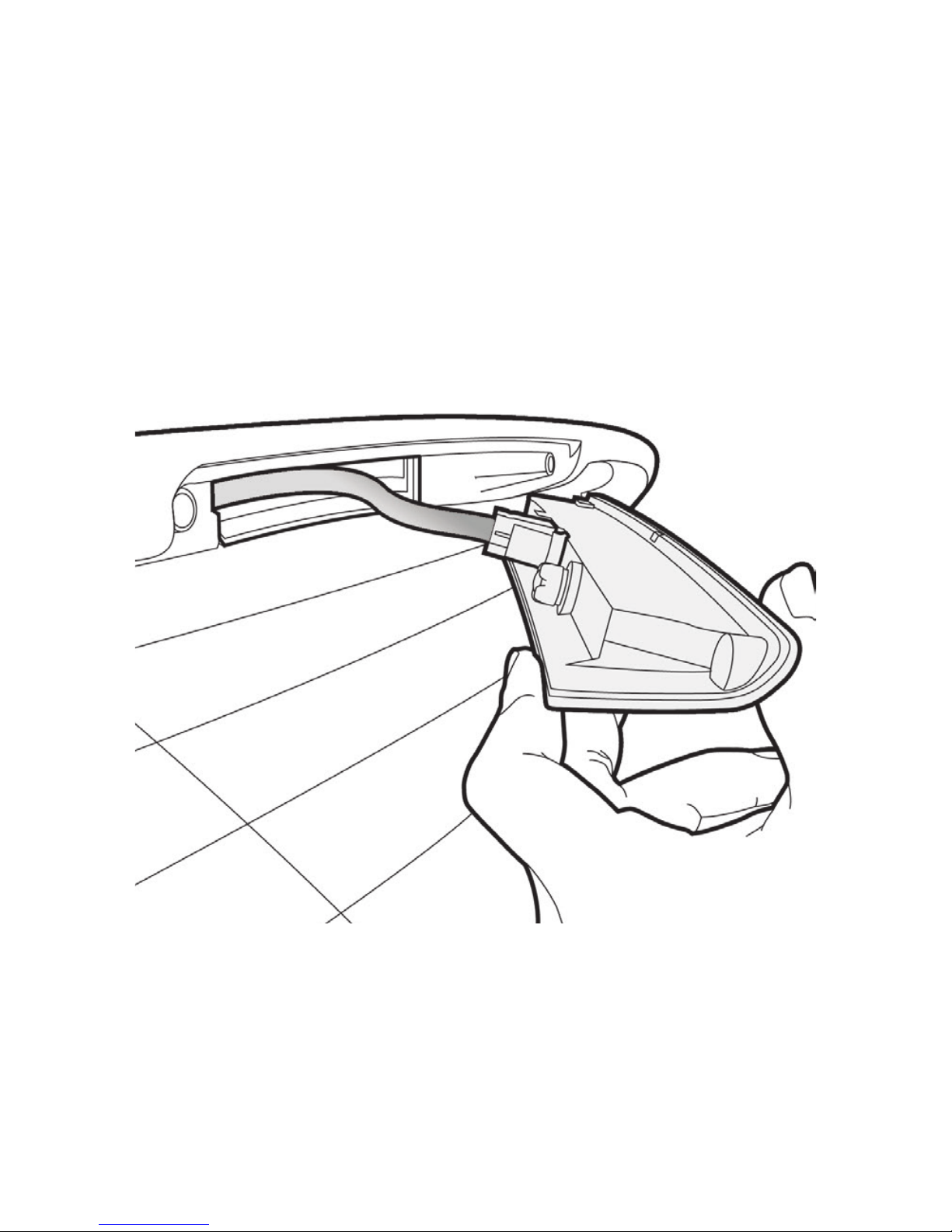
Brake Light Removed
Page 14

WWW.GSTOP.CO.UK
Designed in Great Britain
Version 1.1
Page 15
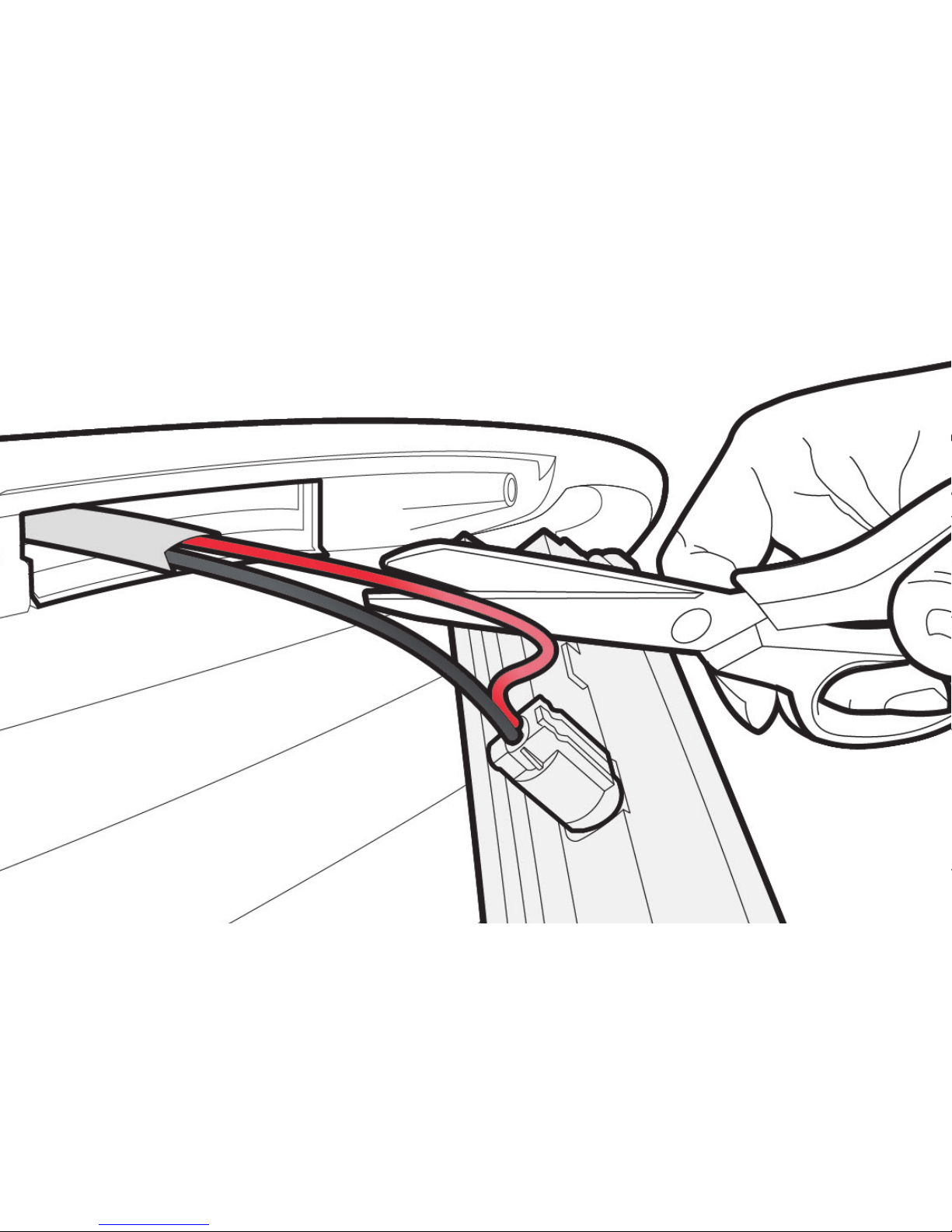
Cut into Brake Light 12V Feed
Page 16
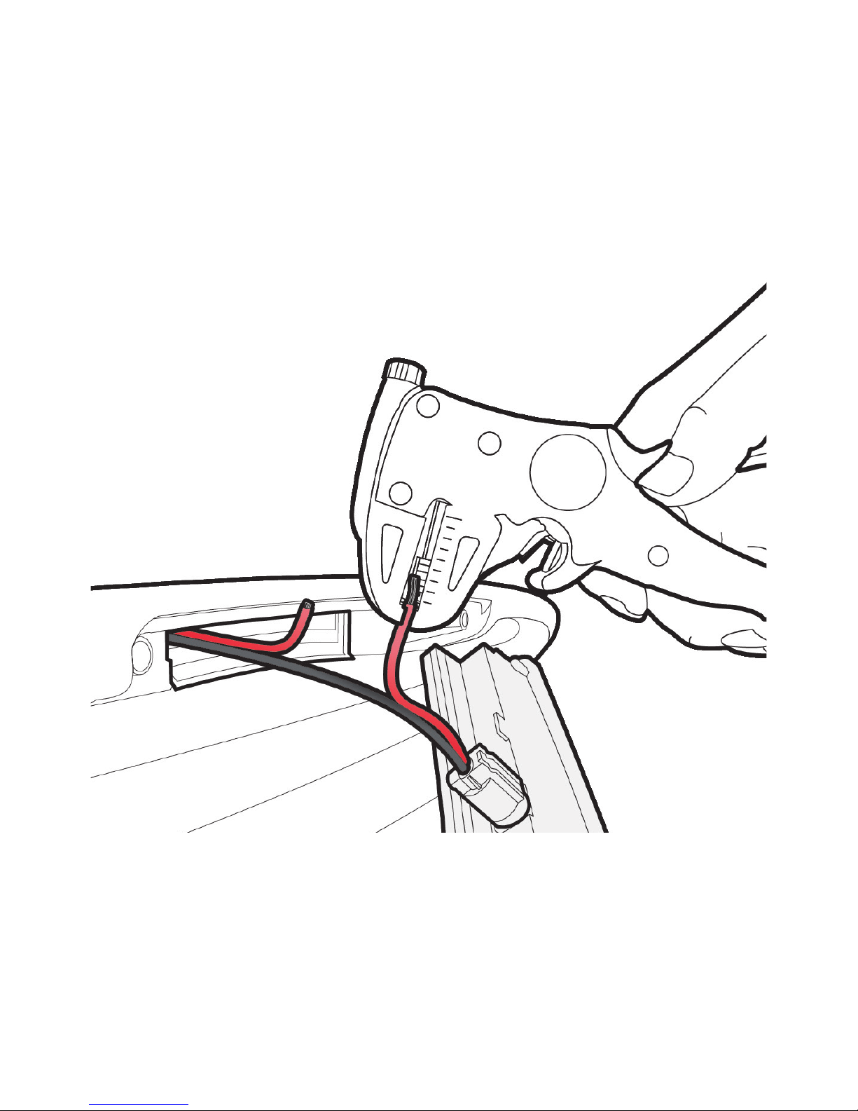
Prepare Wiring for Connection to GSTOP
Page 17
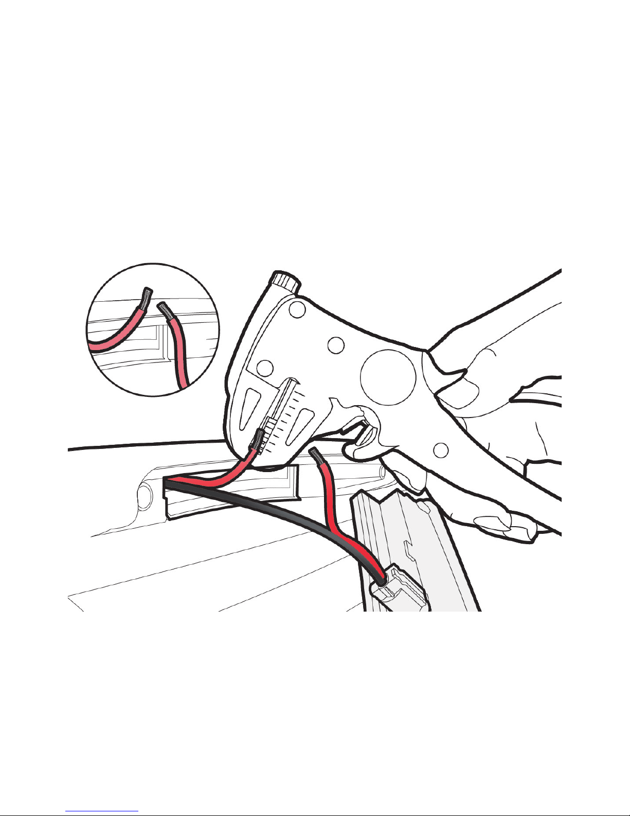
Prepare Wiring for Connection to GSTOP
Page 18
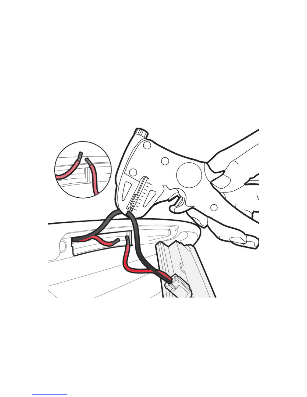
Strip Insulation on Ground Wire
Page 19
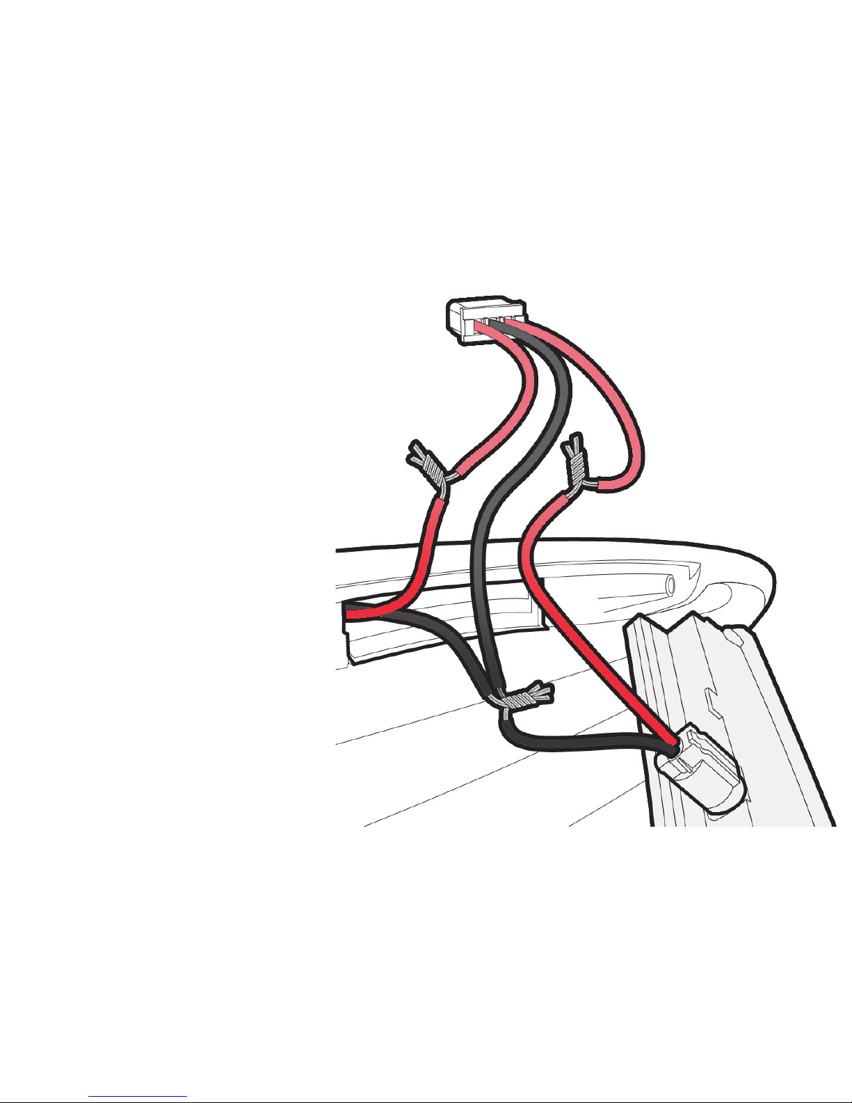
Shows Basic Connection
(If installer wish to Solder)
Page 20
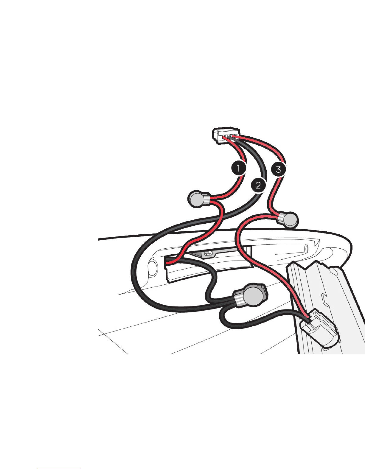
Shows GSTOP Wiring Install
with Supplied Connectors
Page 21
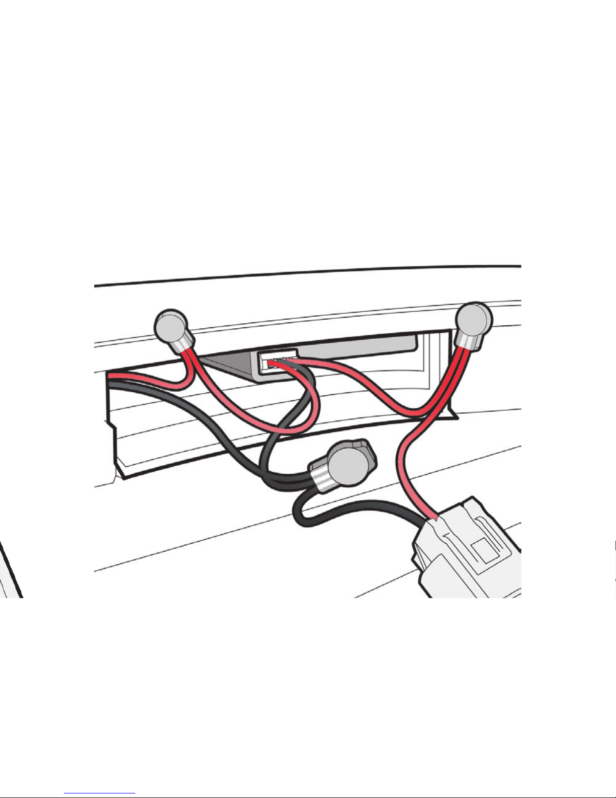
Connect GSTOP Plug to Installed GSTOP Module
Page 22
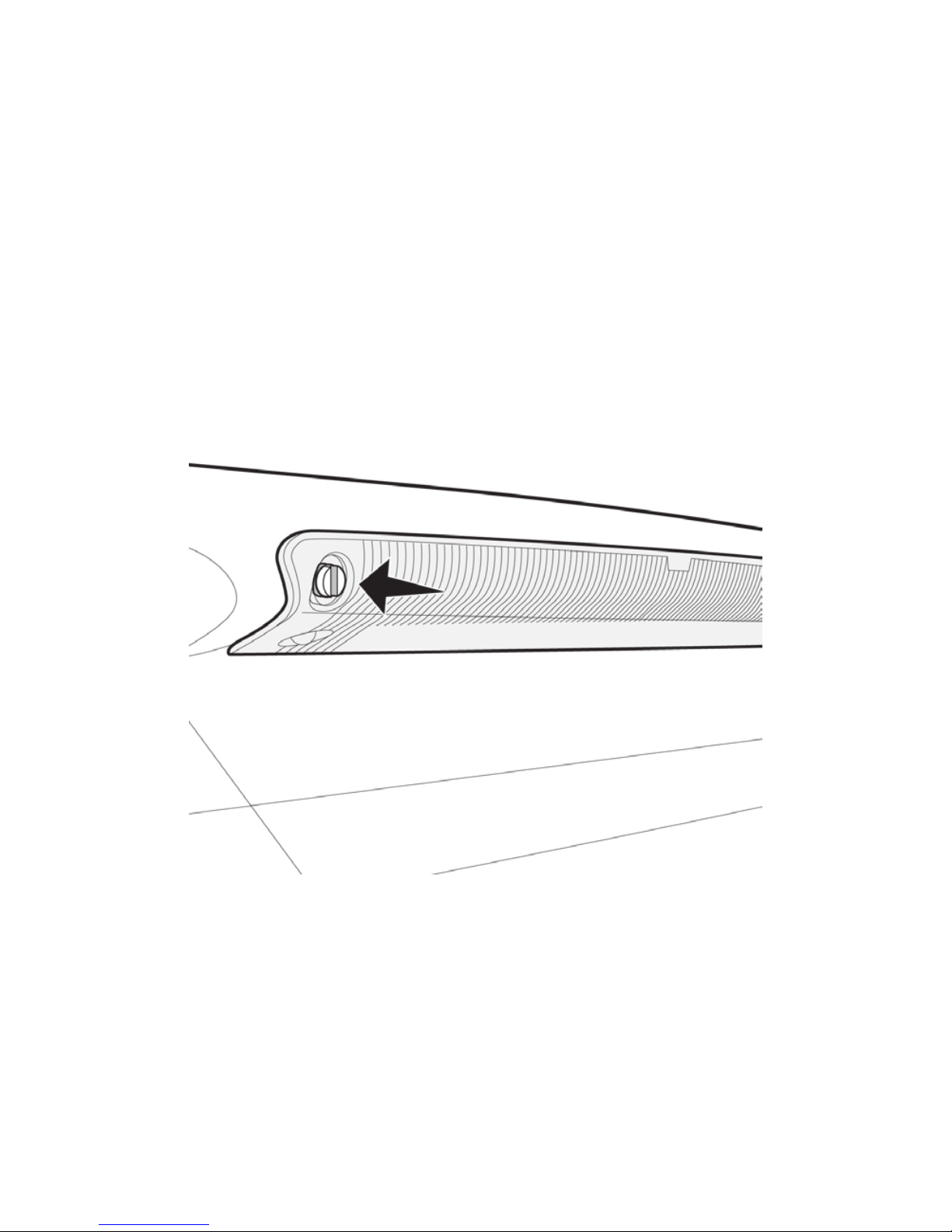
Refit the Brake Light
Page 23

Technical Specification
• GSTOP® LITE Encasement: Flame Retardant ABS Plastic
• Moisture Protection: Protective Lacquer Treated Circuit Board
• FailSafe: Interrupt relay configured ‘Normally Closed’
• Dimensions: (L)46mm (W)27mm (H)6mm~10mm
• Connector: 3 Terminal Snap-Fit
• Input Voltage: 6v~30vdc
• Power Consumption: <200mW
• Power Handling: Max 2 Amp
• (@6v Max = 12Watt)
• (@12v Max = 24Watt)
• (@24v Max = 48Watt)
Package: Cardboard Box / 90mm x 60mm x 16mm
Shipping Weight: Approx 42g
Page 24

Trouble Shooting
Problem: GSTOP® LITE does not flash when I stamp on the brakes?
Solution: GSTOP® LITE is configured to smooth out erratic
movements that maybe caused by bumps and shocks. Heavy
braking in an instant shouldn’t activate GSTOP® LITE easily, try
braking over a longer distance with a sustained moderate to heavy
brake force.
Problem: GSTOP® LITE will only flash when I tilt it towards the
ground?
Solution: GSTOP® LITE is pre-set to 0.6g and 0.8g to activate the
EBLD Warning Signal (Flashing). Gravity exerts 1.0g, so if tilting the
arrow towards the ground activates Trigger.1 and Trigger.2 flash rates,
GSTOP® LITE is working perfectly and as designed. Contact us if you
require assistance: www.GSTOP.co.uk
Page 25

Problem: GSTOP® LITE accelerometer isn’t accurate?
Solution: GSTOP® LITE is shipped with Error Correction enabled.
This means it is dicult to trigger GSTOP® LITE handheld with hand
movements, or with instant shocks or vibration. Slowly Tilt the direction
arrow on GSTOP® LITE toward the ground to test, at a certain angle
GSTOP® Lite should trigger flash stage 1 @ 2Hz (twice a second) and if you
continue to tilt GSTOP® LITE towards the ground, GSTOP® LITE should
then trigger flash stage 2 @ 3Hz (3x a second). If this is the result, the
accelerometer is working correctly. If not, please contact us for assistance;
www.GSTOP.co.uk
Problem: GSTOP® LITE wiring is so tiny, how can it work properly?
Solution: GSTOP® LITE has been designed with a 2 Amp power handling
capability. This is in excess of the rated current of typical high level LED
and/or single bulb Tail Lamps. Also check the wire size in your vehicle,
it should be a good match for the included connectors to work without
issues.
Page 26

Problem: GSTOP® LITE does not work when installed on the vehicle?
Solution: GSTOP® LITE ships with a bench test wiring loom. Test with a
pp3 9v battery, if GSTOP® LITE is working correctly, it may be necessary to
recheck the installation on the vehicle.
Problem: GSTOP® LITE flashes when the tailgate is open and I apply the
brakes?
Solution: Have you installed GSTOP® LITE in the tailgate? Is GSTOP® LITE
forward arrow facing 1.0g of gravity when the boot is open? This maybe
the reason why.. ‘Don’t drive with the tailgate open’. ;-)
Page 27

Help and Support
For help and advise, please consult our website for more information
www.GStop.co.uk
Compliance:
UK/EU Road Legal: E/ECE/324 E/ECE/TRANS/505 (in factory
configuration)
CE Approved
FCC Exempt CFR47:15.103(a)
Directive WEEE (2002/96/EC)
The product is in compliance with the directive WEEE.
GSTOP® Produced by - www.ChipGods.com
Sponsored by - TACHOSOFT®
Page 28

Copyright & Trademark
GSTOP® and the GSTOP LOGO are protected by registered
TradeMark. Any use without notice of the trademark owner is strictly
prohibited. Copyright 2016 - GSTOP® by www.GStop.co.uk
Warranty
• GSTOP® LITE hardware has a 2 year manufacturers warranty. If in
event of a claim, please see our website for return information. www.
GSTOP.co.uk
Liability
The Company does not accept any liability to the Customer for any
indirect or consequential loss or damage, or for any direct or indirect
loss of data, profit, revenue or business in each case, however
caused, even if foreseeable.
 Loading...