

GS Teletech CoverCell25KN Technician's Operational Manual

FCC ID : U88-COVERCELL25KN
HCT CO., LTD.
SAN 136-1, AMI-RI, BUBAL-EUP, ICHEON-SI, KYOUNGKI-DO, 467-701, KOREA
TEL:+82 31 639 8517 FAX:+82 31 639 8525 www.hct.co.kr
Report No. : HCTR1006FR16 1/1
ATTACHMENT E.
- USER MANUAL -

CoverCell25KN
Technician's Operational Manual
Ver. 0.1
Version 0.1 ؼ April 2010
© 2010, GS Teletech, Inc.
2
Contents of Box
Contents Picture Quantity Contents Picture Quantity
Repeater 1EA
Ground Cable
6.6ft (2m)
1EA
Mounting Bracket 1EA
Ground Sems Screw
M4 x 8mm
4EA
Installation Guide CD
1EA
Bracket Sems Screw
M6 x 16mm
4EA
Ethernet Cable
6.6ft (2m)
1EA
Lag Screw
1/2" x 2"
4EA
Power Cord
6.6ft (2m)
1EA
Anchor Bolt Set
1/2" x 2"
4EA
Registration Form 1EA
Version 0.1 ؼ April 2010
© 2010, GS Teletech, Inc.
3
This publication provides instruction for installing Verizon 24dBm Dual Band Inbuilding RF repeater.
The images for the User Interface in this publication may vary from the repeater’s depending on its
S/W Version.
Copyright
© 2010, GS Teletech, Inc.
All Rights Reserved
Printed in Republic of Korea
Revision History
Date Version Changes
04/2010 0.1 Draft
Certification
UL/FCC: This equipment complies with UL and FCC
Version 0.1 ؼ April 2010
© 2010, GS Teletech, Inc.
4
Warnings and Hazards
WARNING! ELECTRIC SHOCK
Opening the BDA (bi-directional amplifier) could result in electric shock and may cause severe injury.
WARNING! EXPOSURE TO RF
Working with the repeater while in operation, may expose the technician to RF electromagnetic fields
that exceed FCC rules for human exposure. Visit the FCC website at http://www.fcc.gov/oet/rfsafety
to learn more about the effects of exposure to RF electromagnetic fields.
WARNING! DAMAGE TO EQUIPMENT
Operating the BDA with antennas in very close proximity facing each other could lead to severe damage to the repeater.
RF EXPOSURE & ANTENNA PLACEMENT
Actual separation distance is determined upon gain of antenna used.
Please maintain a minimum safe distance of at least 8 inch while operating near the donor and the server antennas.
Also, the donor antenna needs to be mounted outdoors on a permanent structure.
WARRANTY
Unauthorized opening or tampering the BDA will void all warranties.
One-year Warranty will start when the ownership of CoverCell25KN Repeater is transferring.
!
CAUTION: REPEATER SHOULD BE INSTALLED AS CLOSE AS POSSIBLE TO POWER SOURCE.
!
CAUTION: THIS REPEATER IS FOR INDOOR USE ONLY AND SHOULD BE LOCATED INSIDE OF BUILDING.
!
CAUTION: RISK OF EXPLOSION IF BATTERY ON CONTROLLER BOARD IS REPLACED WITH AN INCORRECT TYPE.
Version 0.1 ؼ April 2010
© 2010, GS Teletech, Inc.
5
System Specification
Item Downlink Uplink Remark
Cellular
Frequency
(MHz)
A1 869 ~ 880 824 ~ 835
A2 890 ~ 891.5 845 ~ 846.5
B1 880 ~ 890 835 ~ 845
B2 891.5 ~ 894 846.5 ~ 849
PCS Frequency (MHz) 1930 ~ 1990 1850 ~ 1910
Sub Band Filtering
A1+A2 or B1+B2 or A1+B1+A2+B2
5, 10, 15, 20MHz BW (tunable)
Gain
Cellular 80dB 80dB
PCS 80dB 80dB
Flatness 5dB peak to peak Channel power
Input Range
Cellular -56dBm ~ -86dBm Max -56dBm
PCS -56dBm ~ -86dBm Max -56dBm
Output Power
Cellular 24dBm 24dBm EIRP
PCS 24dBm 24dBm EIRP
AGC
Range
Cellular 30dB
PCS 30dB
Roll off
Cellular
≥45dBc@±2MHz
≥30dBc @±0.25MHz (B1+B2 Inside Edge)
PCS ≥30dBc @±1.5MHz
Group Delay ≤ 6μs
Single &
2-tone
Cellular ≤Not to exceed maximum output power@-30dBm
PCS ≤Not to exceed maximum output power@-40dBm
Noise Figure ≤ 7dB
Input Inter-modulation ≤ 10dB
Adjacent
Channel
Power
Cellular
≥ 45dBc @ 750kHz
≥ 45dBc @ 1.98MHz
PCS
≥ 45dBc @ 885kHz
≥ 45dBc @ 1.98MHz
Radiated Spurious Emissions ≤ -13dBm
Frequency Error ± 300Hz @cellular, ± 150Hz @PCS
Signal Quality Rho >0.98
* type of modulation : F9W
Version 0.1 ؼ April 2010
© 2010, GS Teletech, Inc.
6
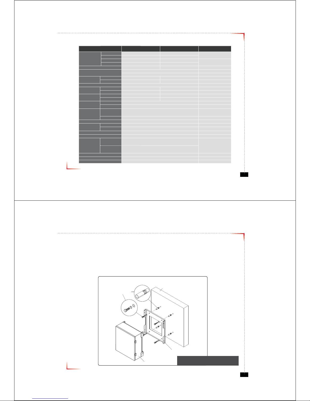
Mounting Repeater
Masonry Wall
1. Using a pencil, mark the location of each of the mounting bracket's four mounting holes on the wall.
2. Drill holes in the wall at the locations marked in step 1.
3. Set the anchors in the wall using a hammer.
4. Locate the four mounting bolts and place a lock washer and flat washer on each bolt.
5. Place the mounting bracket over the four holes with anchors, making sure that the washers are on the
repeater side of the mounting bracket. Tighten bolts until secure.
Anchor Bolt Set
1/2" x 2"
RF Repeater
Masonry Wall
Mounting Bracket
<Figure 1> Mounting the Repeater
on a Masonry Wall
Version 0.1 ؼ April 2010
© 2010, GS Teletech, Inc.
7
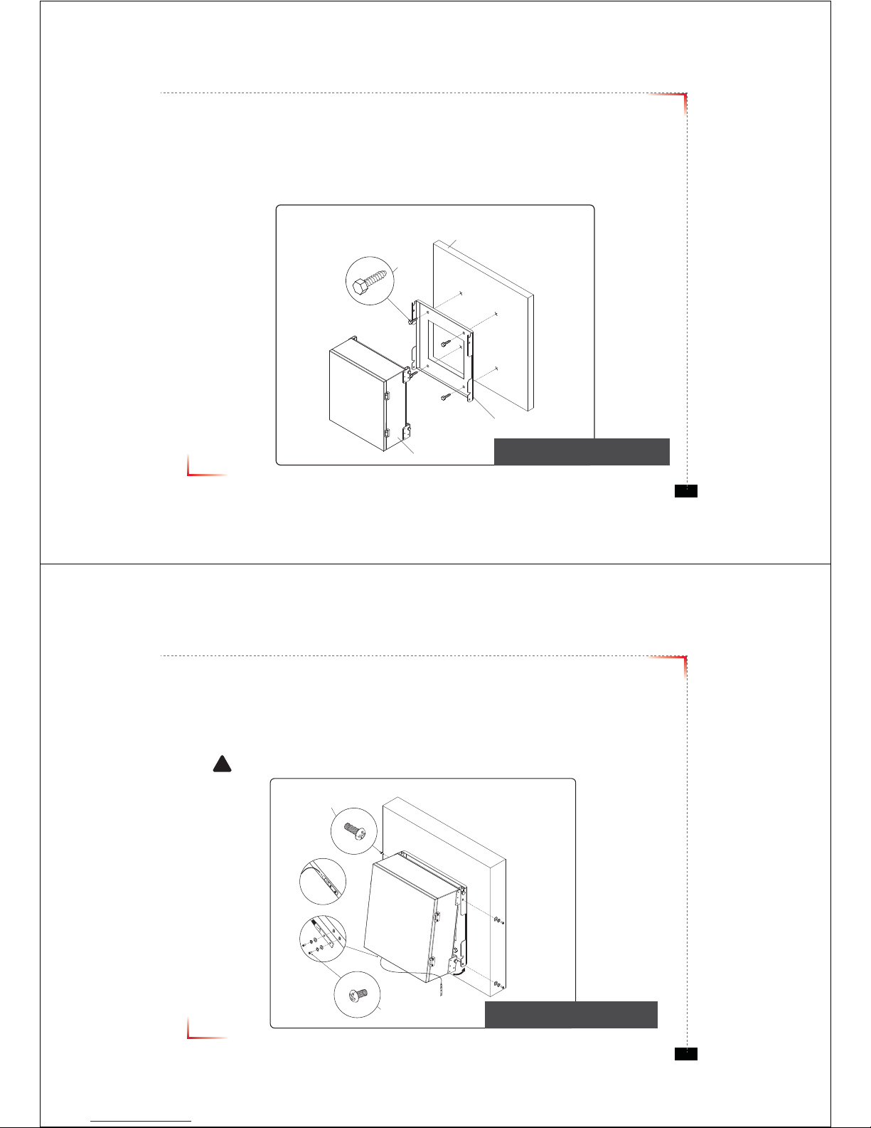
Mounting Repeater
Wood-Framed Wall
1. It is recommended to first attach a sheet of plywood to the wall. The sheet of plywood should be anchored to the studs
in the wall.
2. Using a pencil, mark the location for each of the mounting bracket's four mounting holes on the plywood.
3. Place the mounting bracket over the four lag screws heads.
4. Thread a lag screw at the positions marked in step 2.
<Figure 2> Mounting the Repeater
on a Wood-Framed Wall
Lag Screw
1/2" x 2"
RF Repeater
Wood-Framed Wall
Mounting Bracket
Version 0.1 ؼ April 2010
© 2010, GS Teletech, Inc.
8
Bracket Sems Screw
M6 x 16 mm
Ground Sems Screw
M4 x 8 mm
Ground lug detail drawing
To approved ground source
!
<Figure 3> Hanging and Grounding
the Repeater
Hanging and Grounding
1. Hang the Repeater from the mounting bracket.
2. Locate the four Bracket Sems Screws with installed washers. Tighten bolts until secure.
3. Locate the ground lug on the underside(or side) of the repeater.
4. Crimp the ground cable to the ground lug.
5. Route the free end of the ground cable to an approved(per local code or practice) ground source.
CAUTION
Ground cable must be properly grounded to provide both EMI and voltage surge protection for the repeater.
Version 0.1 ؼ April 2010
© 2010, GS Teletech, Inc.
9
Position Antenna
• Customer specifications should be followed for positioning the antennas properly.
<Figure 4> An installer is directing Donor Antenna to
nearby BTS to receive strong input signal.
Version 0.1 ؼ April 2010
© 2010, GS Teletech, Inc.
10
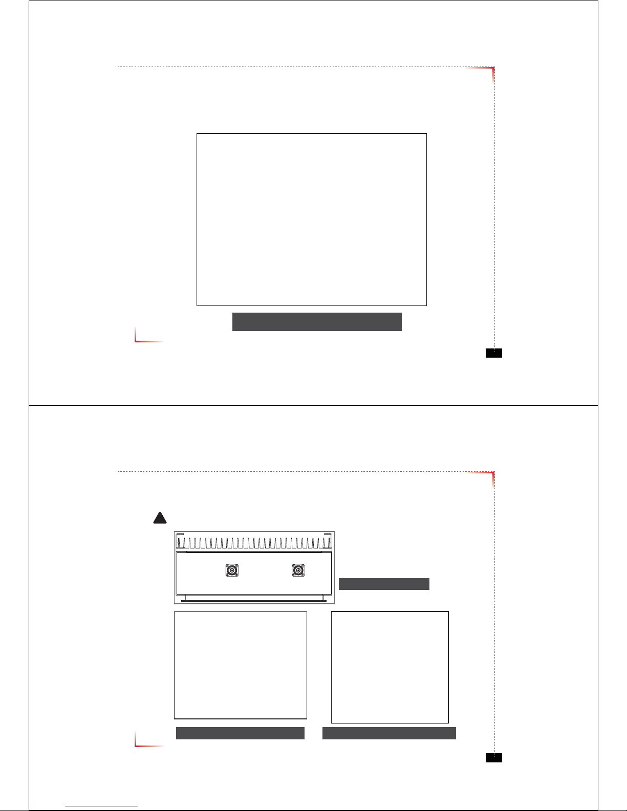
Cable Connections
• Connect Donor and Coverage Antenna
!
CAUTION
Do not connect or disconnect cable from ANT port when power is ON
<Figure 5> ANT Ports
<Figure 6> DONOR ANT Port Connection <Figure 7> Covergare ANT Port Connection
jv}lyhnlGhu{kvuvyGhu{
Version 0.1 ؼ April 2010
© 2010, GS Teletech, Inc.
11
Connecting Power Cable and LED Light Verifi cation
• Connect Power Cable
• When turning on the repeater, AGS (Auto Gain Setup) is automatically activated, which shows LED indicators are
turned on one by one.
• After all the LEDs are on, AGS is complete.
• Please verify that all the LEDs are indicating proper input and output levels.
<Figure 9> AC Power Port Connection <Figure 10> Veri cation of LED Lights
Version 0.1 ؼ April 2010
© 2010, GS Teletech, Inc.
12
LED Indicators
RUN LED : Green light ON
ALARM LED : Yellow light is alarm status
SHUT DOWN LED : Yellow light is shutdown status
<Figure 11> Front LED Display
Version 0.1 ؼ April 2010
© 2010, GS Teletech, Inc.
13
Input Power Signal
• Please note the number of LED bars indicates the RSSI signal strength level at the Donor ANT port.
The tables below indicate the levels.
Less than -85dBm LED 1bar
-84dBm ~ -67dBm LED 2 bars
-66dBm ~ -49dBm LED 3 bars
-48dBm ~ -31dBm LED 4 bars
More than -30dBm LED 5 bars
Common
Version 0.1 ؼ April 2010
© 2010, GS Teletech, Inc.
14
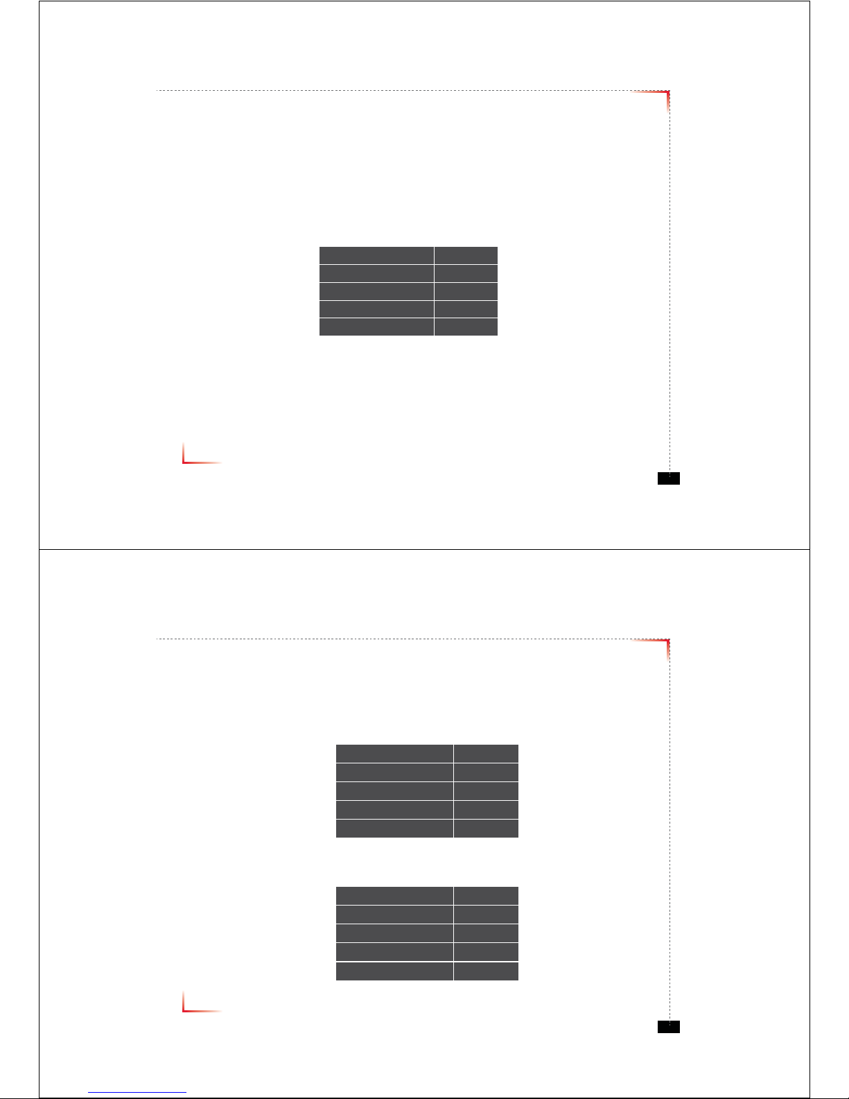
Output Power Signal
• Please note the number of LED bars indicates the downlink signal strength level at the Server ANT port.
The tables below indicate the levels.
Less than +5dBm LED 1bar
+6dBm ~ +10dBm LED 2 bars
+11dBm ~ +15dBm LED 3 bars
+16dBm ~ +20dBm LED 4 bars
More than +21dBm LED 5 bars
Cellular
Less than +5dBm LED 1bar
+6dBm ~ +10dBm LED 2 bars
+11dBm ~ +15dBm LED 3 bars
+16dBm ~ +20dBm LED 4 bars
More than +21dBm LED 5 bars
PCS
 Loading...