

Page 1
30309256 Page 1 Issue 1.03
Features
Providing 16 tones.
Loop powered or external 24V powered.
Power-saving consumption mode and normal
consumption mode (factory default).
Single/dual address programmable.
Standard: EN 54-3.
Description
I-9404 Intelligent Sounder is an audible alarm device
installed in field, which can be activated by fire alarm
control panel in fire control center. After activated, it
will generate strong audible alarm signal to warn
people in field.
A 25.5mm high shallow base and a 40mm high deep
base are available. The sounder comes with the
shallow base. The deep base C-94DB should be
ordered separately. Unless otherwise stated, all
descriptions in this manual take the shallow base as
example.
Connection & Cabling
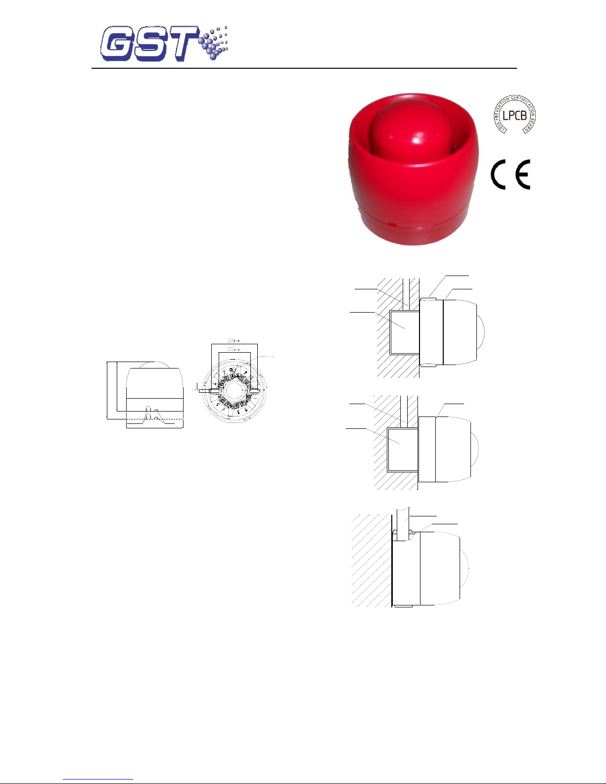
Terminals on the base are shown in Fig. 2.
?110
110.4mm
95.9mm
Shallow Base
Deep Base
Tamper-proof
knockout
Drain Hole
Fig.1
1
D
2
K
1
2
Z
K
Z
1
S
2
D
mm
G
Arrow Upward
Fig. 2
Fig. 1 Fig. 2
Z1 (2), Z2 (4): Loop of the control panel, polarityinsensitive.
D1 (9), D2 (7): To external 24VDC power, polarityinsensitive.
Recommended Wiring
1.5mm2 or above fire cable for D1, D2, Z1 and Z2,
subject to local codes.
Installation
When surface mounted, the sounder should be
placed 0.2m from the ceiling for normal space
height. When the conduit is embedded, the base
can be mounted on the back box. When the
conduit is surface mounted, the deep base should
be adopted. Knock the knockout hole, and connect
the conduit with it. The mounting hole spacing and
mounting direction are shown in Fig. 2. Mounting
method is shown in Fig. 3a and Fig. 4. The conduit
must be embedded when the shallow base is used,
as shown in Fig. 3b.
The base and the sounder are twisted together.
When mounting, remove the sounder, thread
cables through the cable entry in the base and
connect with corresponding terminals, then twist
the sounder onto the base.
Conduit
Knockout
Back Box
Sounder
Fig. 3a
Conduit
Back Box
Sounder
Fig. 3b
Conduit
Sounder
Fig. 4
If the sounder is required to be tamper-proof,
knock down the arch knockout as shown in Fig. 1
and fix it with ST2.9×6.5 self-tapping screws (in
this case, it can only be removed by a cross
screwdriver).
Application
Address, tone, programming method, consumption
mode can be set through P-9910B programmer (refer
to P-9910B Hand Held Programmer Installation and
Operation Manual).
I-9404
Intelligent Sounder
548e/05
0832-CPR-F0037
GST-0003-01
13
Page 2
30309256 Page 2 Issue 1.03
Tone, single/dual address mode and consumption
mode can be set by changing the parameter of a
sounder using P-9910B programmer. Refer to
Table 1 for parameters and P-9910B Hand
Programmer Installation and Operation Manual for
details.
In single address mode, the sounder will sound the
preset tone when activated.
In dual addresses mode,
The sounder will sound the pre-alarm tone
when activating the first address;
The sounder will sound a preset tone (refer to
Table 1) when activating the second address;
The sounder will sound the preset tone (refer to
Table 1) when activating the first and second
address together.
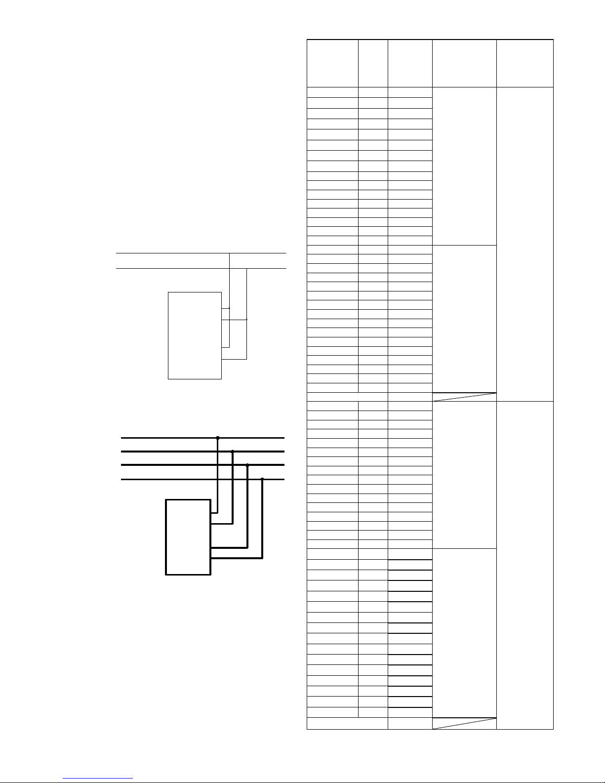
Wiring diagram
Fig.5 shows that the sounder is loop-powered.
Sounder
Z1
D2
D1
Z2
Z1
Z2
Fig. 5
Fig. 6 shows that the sounder is supplied by
an external 24V power.
Sounder
Z1
D2
D1
Z2
Z1
Z2
D1
D2
Fig. 6
Below is an example showing how to set the
sounder addressed 25 as dual addresses, tone 15
and normal consumption mode.
Switch on the P-9910B programmer, input the
password and press the Function key and number 3.
Enter 63 and the Program key. The setting is
successful when P appears on the display. The
sounder is now to be programmed Address No. 25
and 26.
Table 1 shows tone, programming method,
consumption mode for the sounder (Factory default is
single address Tone 14 under normal consumption
mode).
Table 1
Parameter
Tone
Min.
Sound
Level (in
dB) at 1
Meter
Programming
method
Consumption mode
01
01
79
Single
address
PowerSaving
02
02
81
03
03
79
04
04
81
05
05
80
06
06
78
07
07
75
08
08
78
09
09
80
10
10
79
11
11
77
12
12
80
13
13
77
14
14
79
15
15
77
16
16
82
17
01
79
Dual
addresses
18
02
81
19
03
79
20
04
81
21
05
80
22
06
78
23
07
75
24
08
78
25
09
80
26
10
79
27
11
77
28
12
80
29
13
77
30
14
79
31
15
77
32
16
82
Pre-alarm
75
33
01
89
Single
address
Normal
34
02
86
35
03
84
36
04
86
37
05
86
38
06
85
39
07
85
40
08
88
41
09
83
42
10
85
43
11
87
44
12
84
45
13
84
46
14
86
47
15
83
48
16
84
49
01
89
Dual
addresses
50
02
86
51
03
84
52
04
86
53
05
86
54
06
85
55
07
85
56
08
88
57
09
83
58
10
85
59
11
87
60
12
84
61
13
84
62
14
86
63
15
83
64
16
84
Pre-alarm
76
Page 3

30309256 Page 3 Issue 1.03
Specification
Operating
Voltage
Loop: 24V (20V~28V)
Power: 24V (20V~28V)
Standby Current
Power-saving mode:
Loop-powered:
Loop monitor current≤2mA
Start current≤7mA
External 24V powered
Loop monitor current≤1mA
Start current≤2.5mA
Power monitor current≤1.5mA
Start current≤7mA
Note: The sounder can only work at
power-saving mode when
loop-powered with maximum 20
sounders in the loop.
Normal mode:
Loop powered
Loop monitor current≤2mA
Start current≤25mA
External 24V powered
Loop monitor current≤1mA
Start current≤2mA
Power monitor current≤1mA
Start current≤25mA
Power
Consumption
0.84W
Programming
Method
Single / dual address (refer to Table
1)
Programming
Range
1~242
Indoor
Application
Type A
Ingress
Protection
Rating
IP33C
Operating
Temperature
-10℃~+50℃
Relative
Humanity
≤95%, non condensing
Enclosure
Material and
Color
ABS, red
Dimension
(D×H)
ф110mm×110.4mm (deep base)
ф110mm×95.9mm (shallow base)
Mounting Hole
Spacing
55mm~80mm
Weight
About 355g (deep base)
About 327.2g (shallow base)
WEEE Information
2012/19/EU (WEEE directive): Products
marked with this symbol cannot be
disposed of as unsorted municipal waste
in the European Union. For proper
recycling, return this product to your
local supplier upon the purchase of equivalent new
equipment, or dispose of it at designated collection
points.
Tone Type
Tone
Description
01
970Hz
02
800Hz / 970Hz @ 2Hz
03
800Hz -970Hz @1Hz
04
970Hz 1s off / 1s on
05
970Hz, 0.5s / 630Hz, 0.5s
06
500Hz - 1200Hz×3, 3.5s on / 0.5s off
07
2850Hz, 0.5s on / 0.5s off×3 / 1.5s off
08
2850Hz 0.4s on, 0.3s off
09
550Hz, 0.7s / 1000Hz, 0.33s
10
1500Hz -2700Hz @ 3Hz
11
2400Hz
12
500Hz -1200Hz @ 0.33Hz
13
2400Hz -2900Hz @ 9Hz
14*
2400Hz -2900Hz @ 3Hz
15
2800Hz 0.4s on, 0.34s off
16*
500Hz-1200Hz, 3.75s / 0.25s off
Pre-alarm*
800Hz 1s off / 1s on
* EN54 Compliant
Accessories and Tools
Model
Name
Remarks
C-94DB
Deep Base
Order separately
P-9910B
Hand Held
Programmer
Order separately
Limited Warranty
GST warrants that the product will be free from defects
in design, materials and workmanship during the
warranty period. This warranty shall not apply to any
product that is found to have been improperly installed
or used in any way not in accordance with the
instructions supplied with the product. Anybody,
including the agents, distributors or employees, is not
in the position to amend the contents of this warranty.
Please contact your local distributor for products not
covered by this warranty.
Page 4

30309256 Page 4 Issue 1.03
Appendix Tones Recognized by LPCB
1. Tone 14 – Sound Level dB(A)
2. Tone 16 –Sound Level dB(A)
Normal Mode
Power-saving Mode
Angle
Horizontal
Vertical
Horizontal
Vertical
Max 28V
Min 20V
Max 28V
Min 20V
Max 28V
Min 20V
Max 28V
Min 20V
15°
84.3
83.5
92.4
89.7
83.2
82.0
82.5
82.4
45°
92.6
88.7
92.2
89.9
88.3
90.1
89.5
89.2
75°
94.1
92.9
95.2
92.5
93.1
91.6
94.4
91.7
105°
95.3
95.3
94.8
92.2
89.6
92.5
91.6
94.4
135°
92.4
90.4
92.4
89.8
88.3
89.9
89.6
89.3
165°
87.9
86.3
85.7
83.4
84.2
85.2
83.7
80.4
3. Pre-alarm Tone -Sound Level dB(A)
Normal Mode
Power-saving Mode
Angle
Horizontal
Vertical
Horizontal
Vertical
Max 28V
Min 20V
Max 28V
Min 20V
Max 28V
Min 20V
Max 28V
Min 20V
15°
76.2
76.4
77.0
77.3
73.6
74.0
73.7
77.7
45°
83.6
83.7
82.5
82.7
82.3
82.8
81.3
81.6
75°
85.5
85.2
85.3
85.0
85.8
85.8
85.0
85.1
105°
85.1
84.6
85.3
85.1
85.1
85.1
85.7
85.6
135°
81.7
81.6
82.5
82.1
81.6
81.4
82.2
82.2
165°
75.2
74.4
79.1
78.2
75.5
74.6
77.7
76.8
Normal Mode
Power-saving Mode
Angle
Horizontal
Vertical
Horizontal
Vertical
Max 28V
Min 20V
Max 28V
Min 20V
Max 28V
Min 20V
Max 28V
Min 20V
15°
87.0
85.2
85.7
83.3
81.7
78.6
78.6
75.8
45°
93.3
91.6
90.7
88.1
88.2
85.5
86.7
84.2
75°
93.4
91.4
92.8
90.6
88.5
85.5
88.9
86.2
105°
93.4
90.8
93.2
90.7
88.0
85.3
88.9
86.2
135°
92.4
90.1
92.5
89.9
85.9
83.7
86.9
84.3
165°
90.6
88.4
85.6
82.5
81.4
79.4
81.2
78.7
This document is subject to change without notice. Please contact GST for more information or questions.
Gulf Security Technology Co., Ltd.
No. 80, Changjiang East Road, QETDZ, Qinhuangdao, Hebei, P. R. China 066004
Tel: +86 (0) 335 8502528 Fax: +86 (0) 335 8508942 gst.info@fs.utc.com www.gst.com.cn
 Loading...