

Page 1

Page 2

I-9105R
Intelligent Reflective Beam Detector
Installation and Operation Manual The Intelligent Solution
CONTENTS
I Overview.......................................................................................1
II Features........................................................................................1
III Technical Specifications................................................................2
IV Structure and Operation Principle.................................................4
V Mounting and Wiring.....................................................................6
1. Ambient Conditions for Installation............................................6
2. Mounting Height and Position....................................................7
3. Mounting..................................................................................10
4. Wiring......................................................................................13
VI Commission................................................................................14
VII Cautions......................................................................................16
VIII Operation....................................................................................16
1. Reading Information................................................................16
2. Setting Address Code..............................................................17
3. Setting Sensitivity Level...........................................................17
4. Setting the Device Type...........................................................17
5. Other Functions.......................................................................18
IX Troubleshooting..........................................................................19
X Maintenance ...............................................................................20
XI Accessories.................................................................................21
Appendix 1 Warnings.........................................................................22
Appendix 2 Warranty..........................................................................23
Page 3

I-9105R
Intelligent Reflective Beam Detector
Installation and Operation Manual The Intelligent Solution
1
I Overview
I-9105R Intelligent Reflective Beam detector (the detector) is an
addressable reflective infrared beam smoke detector that has two
signal output ways: loop output and contact output. When the detector is
connected with GST fire alarm control panel directly, state information
will be transmitted through loop between the detector and the control
panel. The detector can be programmed by GST programmer. Code
range is within 1~242. When the detector is not connected with the
control panel, fire and fault information can be transmitted by contacts.
The detector must be used together with a reflector. The number of
reflector(s) to be used (one or four) depends on the distance from the
detector.
With excellent built-in microprocessor, the detector has strong ability of
analysis and judgment. The detector can carry out system adjustment,
compensation of variation of ambient data, and judgment of fire and
fault through fixed algorithm. With new and reasonable design,
esthetical pleasing, flexible judgment and alignment method, it’s easy to
install and adjust. The sensitivity of the detector can be set through
hand held programmer in field, decreasing the demand for cleanliness
of field conditions, and enlarging application areas.
The detector is applicable to historical buildings, warehouses, large
storages, shopping malls, leisure centers, exhibition halls, hotel lobbies,
printing houses, clothing factories, museums and prisons, as well as
places where slight smoke particles.
II Features
1. Wide operating voltage range, big monitoring areas.
2. Combination of the emitting and receiving part makes mounting
easy and optical pathway accurate.
Page 4

I-9105R
Intelligent Reflective Beam Detector
Installation and Operation Manual The Intelligent Solution
2
3. Built-in microprocessor enables intelligent judgment about fire
alarm and fault.
4. The detector can calibrate automatically, which ensures a single
person complete adjustment in short time. It’s also convenient to
operate.
5. Self-diagnosis function can monitor the inner fault.
6. Automatic compensation for factors weakening received signals,
such as a certain of dust contamination, positional excursion and
ageing transmitter.
7. Simple to control and operate by integrating digital bus protocol.
8. Electronically addressed. The address can be programmed in field.
9. Two sensitivity levels can be set in field.
10. The detector’s optical pathway is designed with strong
anti-interference ability.
11. SMT processing technology.
12. Attractive and decent appearance.
13. Standard: EN 54-12.
III Technical Specifications
1. Operating Voltage: 24VDC (15V~28V)
2. Operating Current:
Power current: Commission current ≤20mA
Standby current ≤8mA
Alarm current ≤12mA
3. Loop Output:
Loop Voltage: 24V (15V~28V)
4. Fire, fault contact output
Fire output contact: contact capacity is 28V/2A. Normally open in
normal state, closed in fire condition.
Fault output contact: contact capacity is 28V/2A. Closed in normal
Page 5

I-9105R
Intelligent Reflective Beam Detector
Installation and Operation Manual The Intelligent Solution
3
state, and open in fault condition.
5. Angle of Adjusting: -6°~+6°
6. Maximum angular misalignment: ±0.5°
7. Sensitivity Level:
Level 1: 1.61dB
Level 2: 2.31dB
8. Indication of Detector State:
Commission: Green LED and yellow LED are lit or flashed in a
certain way. Refer to details in Section VI Commission.
Normal monitoring state: Red LED flashes periodically.
Fire: Red LED illuminates when the detector reports fire alarm.
Fire output contact is closed. The fire signal can be transmitted to
the control panel through loop and has to be cleared by the control
panel. Power on the detector again to clear the fire signal if GST
control panel is not connected.
Fault: Yellow LED illuminates. Fault output contact is open. The
detector clears the fault signal automatically if the condition
causing the fault disappears.
Optical pathway obscured totally: the detector first gives fault
signal and turns on yellow LED. 15 second later, it reports fire
alarm, and red LED is turned on; fire output contact is closed.
Yellow LED is turned off, fault output contact is closed. Note: In
this case, it does not necessarily mean there is a fire. After
the obscuration is removed, the detector clears the fault
signal automatically. If fault signal turns to fire signal, it has
to be cleared by the control panel or cutting off power.
9. Operating Environment:
Temperature: -10°C~+50°C
Relative Humidity≤95%, non condensing
10. Monitoring Area: Maximum monitoring area: 14×100=1400m
2
Maximum width: 14m
Page 6
I-9105R
Intelligent Reflective Beam Detector
Installation and Operation Manual The Intelligent Solution
11. Length of Optical Pathway: 8m~100m
12. Ingress Protection Rating:
It is IP20 in ordinary environment; it is IP66 through glue-seal
treatment in special environment.
13. Dimensions:
Length: 206mm Width: 95mm Depth: 95mm
14. Material and Color of Enclosure: ABS, gray
15. Weight: 450g
16. Mounting Hole Spacing:
Spacing for embedding: 158mm
Spacing for surface mounting: 79mm×96mm
IV Structure and Operation Principle
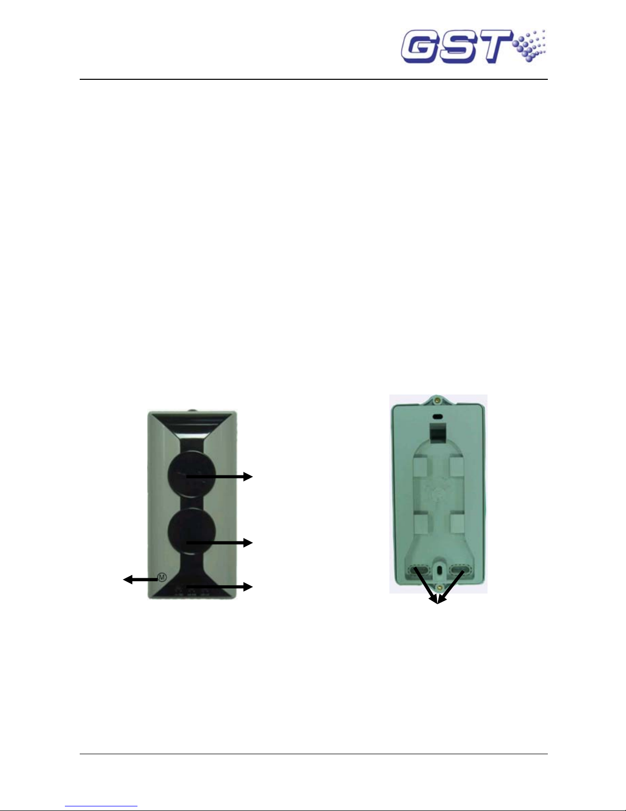
1. Appearance of the detector is shown in Fig. 1.
Cable Entry
Commission
Zone
LEDs
Receiving
Windo
w
Emitting
Window
Fig. 1
2. Internal devices of the detector and positions to be glued are
shown in Fig. 2.
4
Page 7

I-9105R
Intelligent Reflective Beam Detector
Installation and Operation Manual The Intelligent Solution
5
Fig. 2
3. Operation Principle
The detector and reflector are placed oppositely . The detector includes
emitting part and receiving part. Infrared beam of certain intensity sent
out from the emitting part is reflected by the right-angle prisms of the
reflector, and then received by the receiving part of the detector. The
receiving part simultaneously collects and amplifies the returned
infrared beam, analyze and judge the collected signals through its
microprocessor. When the detector is in normal monitoring state, the
intensity of infrared beam received by the receiving part is steady at a
certain level. When smoke particles enter the detecting area, the
intensity of infrared light received by the receiving part falls owing to
light scattering. When the smoke particles reach a certain density, and
the intensity of infrared light received by the receiving part is reduced
below the preset threshold value, the detector alarms fire, illuminates
red LED. And fire output contact is closed. If connected with GST
control panel, the fire signal will be passed to the panel through loop.
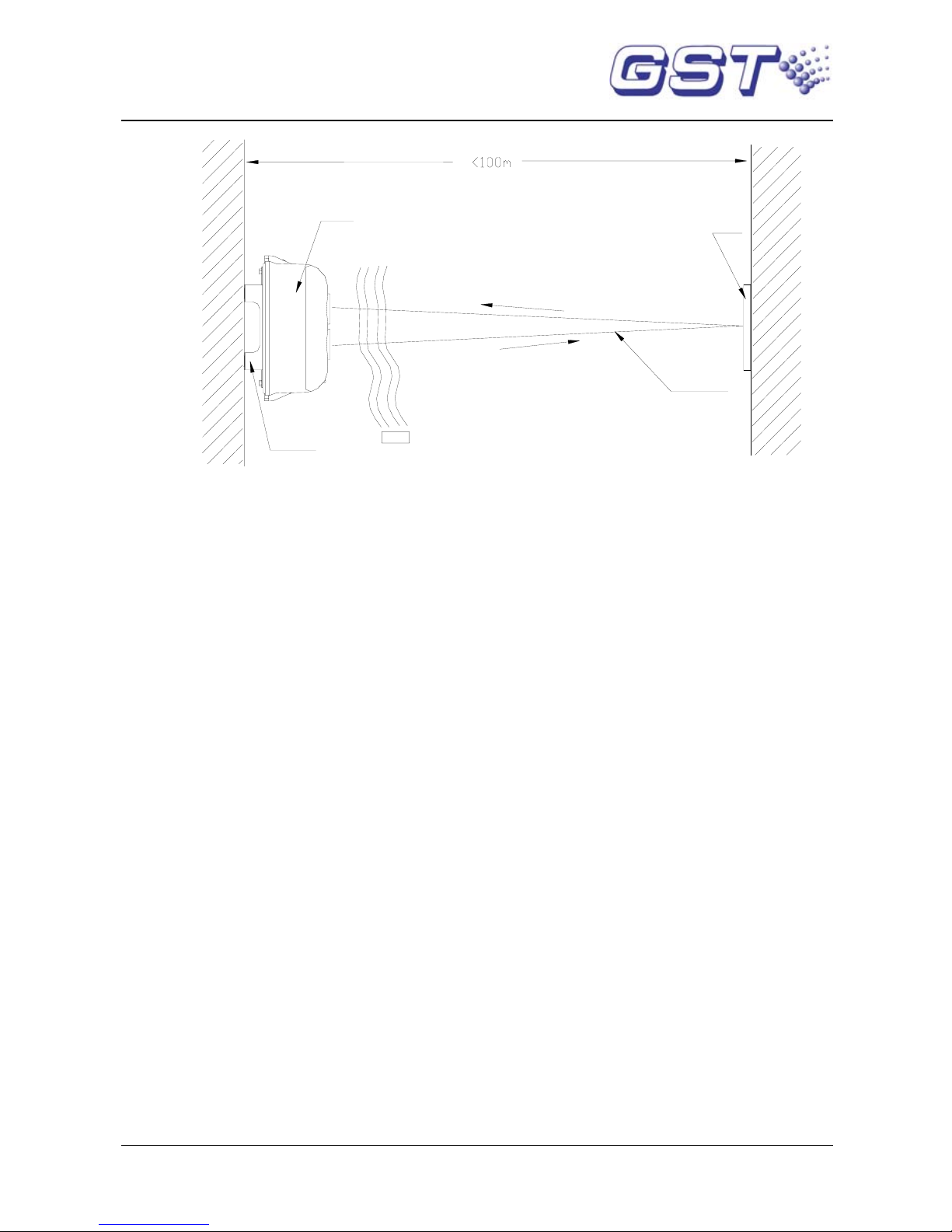
Operation principle is shown in Fig. 3.
A
djusting Wheel
To Be Glued
Mounting Direction
Rotary Rack
Flexible Cable
Reed Switch
To Be Glued
Page 8
I-9105R
Intelligent Reflective Beam Detector
Installation and Operation Manual The Intelligent Solution
Smoke
Reflector
Detector Body
Mounting
Bracket
Infrared
Beam
Fig. 3
V Mounting and Wiring
1. Ambient Conditions for Installation
The detector works on light obscuration principle. Avoid any fixed or
moving obscuration in its optical pathway when installing.
The wall for mounting either the detector or the reflector should be firm
and smooth. The detector is mounted vertical to the wall. The wall may
seem to be smooth, but corrugated or uneven, or may be changed by
the environment (in rainy season or in winter) and the installer should
ensure the detector not affected by these factors. If the detector is
installed on sustaining rack similar to metal tube, make sure the
sustaining rack fixed firmly.
Not Fit For Locations where:
¾ Space height is over 40m.
¾ It is not roofed.
¾ Space height is less than 1.5m.
¾ There are a lot of dust, powder or vapor.
6
Page 9

I-9105R
Intelligent Reflective Beam Detector
Installation and Operation Manual The Intelligent Solution
¾ It is clean normally, but can be dusty in some special cases.
¾ Temperature is high. Note: Temperature at top part of a
workshop with transparent roof may be over 50℃ when
there is sunshine.
¾ There is no access for maintenance.
¾ The Mounting wall or fitting is greatly affected by mechanical
vibration.
¾ There are fixed or moving objects within 1m from the
detector’s optical pathway.
¾ There is strong magnetic field.
2. Mounting Height and Position
The mounting height of the detector and reflector should be most
accessible by smoke into beam zone. The following recommendations
are for reference:
a) When space height is not over 5m, the detector and reflector
should be mounted on the two facing walls 0.5m from the ceiling, as
shown in Fig. 4.
Reflector
Detector
5m
4.5m
Fig. 4
7
Page 10

I-9105R
Intelligent Reflective Beam Detector
Installation and Operation Manual The Intelligent Solution
b) When space height is between 5m and 8m, the detector and
reflector should be mounted on the two facing walls 0.5m to 1m
from the ceiling, as shown in Fig. 5.
Detector
Reflector
7m
6m
Fig. 5
c) When space height is more than 8m, the roof is normally
gabled without ceiling, the detector and reflector should be
mounted on the two facing walls about 8m from the floor, ensuring
that the vertical distance between the detector/reflector and top of
the building is not less than 0.5m, as shown
in Fig. 6. The distance
should be 7m from the detector to the floor.
8
Page 11

I-9105R
Intelligent Reflective Beam Detector
Installation and Operation Manual The Intelligent Solution
Detector
Detector
Reflector
Reflector
7m
8m
Fig. 6
d) For gable structure with space height about 8m, the detector
and reflector should be mounted on the two facing walls 1.5m from
the gabled girder, as shown in Fig. 7.
Detector
Detector
Reflector
Reflector
6.5m
8m
Reflector
Detecor
Fig. 7
e) If the surroundings are glass or transparent plastic, please
place the detector on the south wall in a building. If the detector
9
Page 12

I-9105R
Intelligent Reflective Beam Detector
Installation and Operation Manual The Intelligent Solution
cannot be mounted northward, then place the detector on the west
wall. For applications where sunlight can reach the detector after
reflected, please consider mounting a sunshade over the
detector’s optical pathway or contact our field application engineer
for a solution.
3. Mounting
1) Setting Length of Optical Pathway
Before installation, you need to set the length of optical pathway
first by setting device type of the detector . The detector can work at
two levels of length. When mounting distance between the
detector and the reflector is not less than 40m (but not more
than100m), the detector type should be set at “52” (factory default).
When the mounting distance between the detector and the
reflector is less than 40m (but more than 8m), the detector type
should be set at “51”. Refer to Section VIII Operation for detailed
setting methods.
2) Mounting the detector
Align the detector and the reflector horizontally on the two facing
walls in monitoring area, as shown in Fig. 8
Fig. 8
10
Page 13

I-9105R
Intelligent Reflective Beam Detector
Installation and Operation Manual The Intelligent Solution
The detector can be surface-mounted in two ways: with conduit
embedded surface-mounted.
(1)Embedding conduit
a. Remove the detector’s top cover.
b. Align the base of the detector over the back box and mark
the positions of mounting holes on the wall.
c. Drill two holes at the marked positions, and push two ∅6
plastic expansion bolts in.
d. Thread the wires through the cable entry, ensuring the
length of wires inside convenient for connection.
e. Fix the detector base on the wall with two plastic
expansion bolts and flat washers.
Mounting method is shown in Fig. 9.
Back Box
Plastic Expansion Bolt
Fig. 9
(2)Conduit surface mounting
a. Put the mounting bracket at position intended to
install the detector; mark the locations of the four
holes of mounting bracket on the wall.
11
Page 14

I-9105R
Intelligent Reflective Beam Detector
Installation and Operation Manual The Intelligent Solution
b. Drill the holes on marked positions, and push ∅6
plastic expansion bolts in.
c. Fix the mounting bracket on the wall with four ∅6
plastic expansion bolts and flat washers.
d. Remove the detector’s top cover; thread the wires
through the cable entry, ensuring the length of wires
inside convenient for connection.
e. Fix the detector base onto the bracket with two M4×
10 bolts and flat washers.
f. The mounting bracket should be earthed through the
mounting hole.
Mounting method is shown in Fig. 10.
Bracket
Plastic Expansion B olt
Conduit
)
Holes for fixing
the detector
Bracket
Earth label
Mounting hole
Fig. 10
3) Mounting the Reflector: The reflector is mounted opposite
the detector but in line with it. When the distance between the
detector and the reflector is more than 8m (less than or equal
to 40m), one reflector is enough. When the distance is more
than 40m (less or equal to 100m), four reflectors are needed.
Two ∅6 plastic expansion bolts are needed to fix a single
reflector. Mounting size is shown in Fig.11a. If four reflectors
12
Page 15

I-9105R
Intelligent Reflective Beam Detector
Installation and Operation Manual The Intelligent Solution
are needed, place them seamlessly as shown in Fig. 11b.
Unit: mm
Fig. 11a
Fig. 11b
4. Wiring
Connect 24VDC power wire (without polarity) to terminal D1 and D2 of the
detector in field. Connect the control panel loop (polarity insensitive) to
terminal Z1 and Z2. The reflectors need not to connect with wires. K11,
K12 are fire output contacts. K21 and K22 are fault output contacts.
Terminals are shown in Fig. 12.
13
Page 16

I-9105R
Intelligent Reflective Beam Detector
Installation and Operation Manual The Intelligent Solution
K11K12K22 K21 Z2
Z1
D2
D1
Fig. 12
Wiring: 1.5mm
2
above fire cable connecting with D1 and D2. 1.0mm2 or
above twisted pair connecting with Z1, Z2, K11, K12, K21, and K22. Cross
section for earth cable should not be less than 1.0 mm
2
.
Note: If the detector is mounted in special environment where
there are slight dust or where it’s damp, seal the three positions
shown in Fig. 2 (two mounting holes and one cable entry) with
glass glue or 703 silica gel after the detector is fixed and wiring is
finished to ensure the detector work stably.
VI Commission
1. Steps
a) Take off the protective membrane carefully on the surface of the
reflector and the detector. Do not scratch or contaminate their
surfaces.
b) Remove the detector’s top cover, and connect to 24VDC power. Two
minutes later, put the magnet of commission tool close to the reed
switch (around the red LED) of detector’s interface board. There may
be two cases with the LEDs:
(1)Green LED flashes.
(2)Green LED illuminates continuously.
Take away the commission tool.
c) If green LED flashes, it means the received light is quite weak (the
slower the flashing frequency , the weaker the received light signal is).
Tune the adjusting wheel and rotary rack on the detector to align the
light beam until green LED is lit continuously, showing that the light
received by the detector is strong. Then stop regulating and enter
14
Page 17

I-9105R
Intelligent Reflective Beam Detector
Installation and Operation Manual The Intelligent Solution
15
step d).
If green LED illuminates continuously, it means the received light is
quite strong, you can go straight to step d).
Note: Observe the detector’s optical p ath way carefully to ensure
that the received light signal is reflected by the reflector rather
than by obscurations like wall, ceiling, or pillar. If uncertain,
verify by covering the reflector with opaque objects.
d) Put on the top cover gently, and screw the two bolts on the cover.
e) The green LED illuminates continuously. Put the magnet of
commission tool close to the zone where marked
○
M until yellow LED
illuminates constantly, then remove the commission tool quickly and
make sure there is no obscuration on the optical pathway. About 5
seconds later , the detector begins to adjust automatically. Y ellow LED
flashing means weak light, green LED flashing means strong light. If
red LED, yellow LED and green LED flash alternately , this means the
detector failed to adjust automatically and cannot enter normal
monitoring state. Please open the detector’s top cover and do
adjustment from step b). If yellow LED and green LED illuminate no
more, and red LED flashes periodically, this means the detector is at
the best position and has entered normal monitoring state. The
commission is finished.
2. Fire alarm test
After the detector has been in normal monitoring state for 20
seconds, cover the receiving window and emitting window with the
IR Light Filter (please use the part for fire alarm test), the detector
should report fire alarm in 30 seconds and red LED should turn on.
3. Fault test
Cover the receiving or emitting window of the detector quickly with
the IR Light Filter (please use the part for commission) to obscure
the optical pathway. Yellow LED of the detector should be turned on.
Taking off the filter immediately, yellow LED of the detector should be
Page 18

I-9105R
Intelligent Reflective Beam Detector
Installation and Operation Manual The Intelligent Solution
16
turned off.
4. Failed Detector
During testing, repair failing detectors according to directions in
Section IX Troubleshooting and X Maintenance, and test again, if
they fail again, return them to factory for repair.
VII Cautions
1. Power up only after all devices are well connected.
2. Adjust the detector after installation and maintenance.
3. Under adjusting condition, both the detector loop and fault output
contact transmit fault signal.
4. The detector base should be fixed directly on solid wall or frame
that will not be deformed by vibration. Any deformable material
such as paperboard, plastic board, foam board or thin wood board
should not be placed between the base and the wall or the bracket.
VIII Operation
The detector can be simply programmed by a hand held programmer.
Address, device type and sensitivity level of the detector can be set with
a programmer. Open the detector’s top cover, connect I
2
C cable of hand
held programmer (PS/2 cable) with XT3 of the detector. Turn on the
power of hand held programmer, input 2, 5, 9 and Function to enter I
2
C
programming mode, the screen shows a “0”. After carrying out operation
needed, input 2, 5, 9 and Function again to exit I
2
C programming mode
and return to power-on state
1. Reading Information
The hand held programmer can conveniently get original information like
address code, sensitivity level and device type. Refer to details below:
z Enter I
2
C programming mode, the screen shows a “0”.
z Press Test, the screen shows the address code of the
detector.
Page 19

I-9105R
Intelligent Reflective Beam Detector
Installation and Operation Manual The Intelligent Solution
17
z Press Up, the screen shows sensitivity level and device type in
sequence.
z Press Down, the screen shows above contents in opposite
way
2. Setting Address Code
The detector offers address code programming for field application.
Refer to operation below:
z Enter I
2
C programming code, and the screen is a “0”.
z Input address code for programming(1~242).
z Press Program to start programming. “P” will be shown when
successful, otherwise an “E” will be shown.
z If programming is successful, press Clear, the screen will
show a “0”, and you can go on with further operations.
z If programming fails, press Clear, the screen will show a “0”,
input address code once more.
3. Setting Sensitivity Level
The hand held programmer can set two sensitivity levels to the
detector. 2 is sensitivity one, and 3 is sensitivity two, referring to
detailed operations below:
z Enter I
2
C programming mode of hand held programmer, and
the screen shows a “0”.
z Input unlock password, press Clear, and open the lock.
z Press Function then the figure “3”, the screen shows a “-”.
z Input sensitivity level to be set, and press Program to begin
programming. The screen will show a “P” when if
programming is successful, otherwise it will show an “E”.
z Clear pressed, the screen shows “0”, and you can go on with
further operations.
4. Setting the Device Type
You can also set the device type of the detector through a
programmer, referring detailed operations below:
Page 20

I-9105R
Intelligent Reflective Beam Detector
Installation and Operation Manual The Intelligent Solution
18
z Enter I2C mode of the programmer, and the screen
s h o w s “0”.
z Input unlock password, press Clear, and open the lock.
z Press Function and then figure “4”, the screen shows “-”.
z Input the device type to be set, press Program to begin
programming. “P” will be shown when successful, otherwise
“E” will be shown.
z Pressing Clear shows “0” on the screen, and you can go on
with further operations.
Note: The hand held programmer has lock password to
prevent non-special personnel from modifying some
important data. “456” is unlocking password; “789” is
locking password.
5. Other Functions
1) Automatic Compensation of Light
When dust exists in the working environment of the detector, the
emitting window, receiving window and reflector will be covered
with dust, which will affect normal operation. In order to solve the
problem, we designed the function of automatic compensation of
light. When there is dust on windows, the detector can judge the
amount of dust, and compensate the received signal through
internal program and circuit to ensure the detector can continue to
work normally. The detector gives fault signal when dust on the
lens and reflector surface reaches a certain level and light
compensation reaches the limit for the detector to work normally.
2) Self-diagnosis on Optical Signal
The detector has functions of checking emitting, receiving and
amplifying circuit. When there is fault with these three parts of
circuit during operation, the detector will generate fault
information.
Page 21

I-9105R
Intelligent Reflective Beam Detector
Installation and Operation Manual The Intelligent Solution
19
IX Troubleshooting
Common problems and repair methods are as shown in Table 1.
Table 1
Problems Reasons Repair Methods
Working LEDs
not lit after
power up.
a) 24V power off
b) Working LEDs damaged.
c) Transient suppressor VD12 damaged.
d) DiodeVD1, VD2, VD10, VD11
breakdown resulting in short circuit
with ground.
e) N1, N2 damaged.
f) The flexible cable inside was not
connected, or not connected correctly .
If the problems are
mentioned in a) ~ e) ,
replace the component
with problem.
If in f) connect again in
right way.
Fault LED
constantly
illuminates
after power up
Wrong device type. Program the device type
51 or 52 again according
to Section VIII Operation.
Reports fault
after the
control panel
powers on
and registers
The detector is not in normal working
state.
Commission once more.
Green LED
constantly
flashes after
power on
a) Emitting diode or circuit damaged.
b) Receiving diode or amplifying circuit
damaged.
Replace the component
with problem.
Gives fault
signal after a
period of
normal
operation
The detector can’t work normally. Commission once more
Alarms fire
after operation
for some time,
and gives fault
signal after
restart
The detector has deviated due to
external vibration.
Commission once more
Page 22

I-9105R
Intelligent Reflective Beam Detector
Installation and Operation Manual The Intelligent Solution
20
Fire signal
cannot be
cleared
a) There are obscuration on the optical
pathway between the detector and
the reflector.
b) The angle of optical pathway has
changed and need to be aligned
again.
c) The emitting diode or circuit
damaged.
d) The photodiode or amplifying circuit
damaged.
If the problems are
mentioned in a), b),
commission once again.
If in c), d), replace the
component with problem.
The control
panel can’t
receive
fire or fault
signals.
No registration.
Register again.
X Maintenance
1. If the detector gives fault signal after working for a long time, first
check whether the detector is damaged or not, and make sure that it
is fixed to the wall or other fittings. Then check whether it is the
accumulating dust and positional excursion, causing compensation
fault, then consider other types of fault.
2. If emitting window, receiving window and reflector surface are found
contaminated, clean them with soft cloth and alcohol (avoid
scraping). Never use water or other chemicals. Commission the
detector again after cleaning and make it in monitoring state.
3. The detector is fire protection product, whose operation must be
well recorded by the personnel on duty and shift.
4. Personnel on duty should be familiar with the functions and
operation process of the device to avoid mis-operation.
5. Test alarm function once half a year.
Page 23

I-9105R
Intelligent Reflective Beam Detector
Installation and Operation Manual The Intelligent Solution
21
XI Accessories
Accessories provided with the detector are as follows:
Four plastic expansion bolts.
One bracket.
Two M4×10 cross recessed pan head screws.
One IR Light Filter.
Six ∅4 flat washers.
One commission tool.
Page 24

I-9105R
Intelligent Reflective Beam Detector
Installation and Operation Manual The Intelligent Solution
22
Appendix 1 Warnings
Limitations of Smoke Detector
The smoke detector is designed for triggering and initiating emergency
fire equipments, but it only functions when matching with other
equipments. Installation of this smoke detector must conform to
electrical codes and standards in your country.
The smoke detector cannot work without power . It cannot work if power
is cut off for any reason.
The smoke detector may not sense fire that where smoke cannot reach
it, such as in chimneys, in walls, on roofs, or on the other side of closed
doors.
The detector also may not sense a fire on another level of a building.
Therefore, detectors should be placed on every level of a building.
All types of smoke detector have limitations. Because fires develop in
different ways and are often unpredictable in their growth, it is
impossible to predict which type of detector will provide the earliest
warning. No types of smoke detector can sense every kind of fire every
time. Generally speaking, detectors may not warn you about fires
caused by insufficient safety measures, violent explosions, leaking gas,
improper storage of flammable materials like diluents and other safety
hazards, arson or children playing with fire. The alarm of a smoke
detector used in high velocity environment will be delayed due to
dilution of smoke by frequent and fast airflow. What’ s more, the smoke
detector has to be maintained frequently because there will be more
dust contamination.
The smoke detector cannot last forever. In order to keep the detector
working in good condition, please maintain the equipment continuously
according to recommendations from manufacturers and relative nation
Page 25

I-9105R
Intelligent Reflective Beam Detector
Installation and Operation Manual The Intelligent Solution
23
codes and laws. Take specific maintenance measures on the basis of
different environments.
The smoke detector contains electronic parts. Even though it’s made to
last for a long period of time, any of these parts could fail at any time.
Therefore, test your smoke detector at least every half-year according
to national codes or laws. Any smoke detectors, fire alarm devices or
any other components of the system must be repaired or replaced as
long as they fail.
Appendix 2 Warranty
GST warrants that the product will be free from defects in design,
materials and workmanship during the warranty period. This warrant y
shall not apply to any product that is found to have been improperly
installed or used in any way not in accordance with the instructions
supplied with the product. Anybody, including the agents, distributors or
employees, is not in the position to amend the contents of this warranty.
Please contact your local distributor for products not covered by this
warranty.
Page 26

GST China
Gulf Security Technology Co., Ltd.
No. 80, Changjiang East Road, QETDZ, Qinhuangdao, Hebei,
P. R. China 066004
Tel: +86 (0) 335 8502528
Fax: +86 (0) 335 8508942
Email:
sales@gst.com.cn
www.gst.com.cn
GST UK
Global System Technology PLC
Lion Court, Staunton Harold Hall, Melbourne Road, Ashby de la Zouch,
Leicestershire, England LE65 1RT
Tel: +44 1283 225 478
Fax: +44 1283 220 690
Email:
info@gst.uk.com
www.gst.uk.com
GST Dubai
Global System Technology PLC
PO Box 17998 Unit ZA04 JEBEL ALI Free Zone,
Dubai, UAE
Tel: +971 (0) 4 8833050
Fax: +971 (0) 4 8833053
Email:
info@gst.uk.com
www.gst.uk.com
 Loading...