

Page 1
30303644 Issue 1.05
Features
Electronically addressed. The address is
modified in field.
Built-in microprocessor can store 14 history
records.
Drift compensation, to suit environment changing
extensively.
Self-diagnostic.
Standard: UL 268.
Description
I-9102(UL) Intelligent Photoelectric Smoke Detector
(the detector) can form fire alarm system connecting
with fire alarm control panel. The detector illuminates
indicators to indicate fire alarm status and transmits
the fire signal to the control panel.
Using infrared scattering technology, the detector
receives very weak infrared light under normal
smokeless condition. If smoke particles enter the
chamber, the received light signal will increase by
scattering. When smoke density reaches a pre-set
level, the detector will alarm out. In order to reduce
interference and power consumption, the emitting
circuit works in pulse mode to prolong the life of IR
LED.
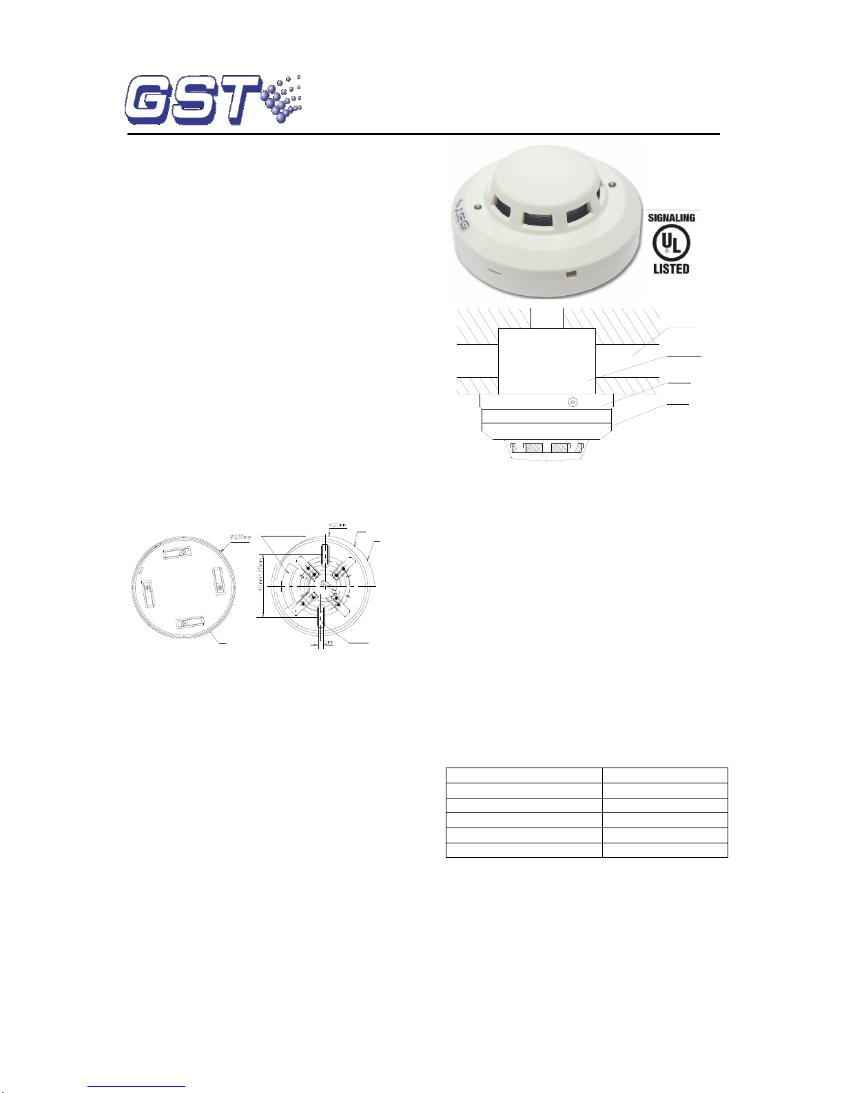
Connection and Cabling
Fig.1 shows the detector bottom and Fig. 2 the base.
C
D
Z
-
0
3
A
B
Base Record Label
Mounting Hole
Distance
Fig. 1 Fig. 2
There are four conducting piece on the base, each
carrying a terminal with numbers. The detector loop in
the conduit can be connected with any two diagonal
conducting pieces (polarity-insensitive). The other two
are used to fix the detector accessorily.
Recommended Cabling
1.0mm2 or above fire cable for detector loop, subject to
local codes.
UL Listed Compatible Control Panel: GST-M200
Installation
A fixed installation direction is ensured by the location
elements on the detector and the base. Fix the base
with two tapping screws, and then align mark C on the
detector with A on the base, rotate the detector to align
mark C with mark B (Refer to Fig. 1 and 2 for the
position of the marks), the detector will be fitted to the
base. Mounting of the detector is shown in Fig. 3.
Application
The detector is applicable to hotels, restaurants, office
buildings, teaching buildings, banks, warehouses,
libraries, computer rooms and switch rooms, etc.
Address can be programmed through programmer in
field. Refer to the P-9910B Hand Held Programmer
Installation and Operation Manual for further details.
Detector
Base
Back Box
Conduit
Fig. 3
Testing
Before testing, notify the proper authorities that the
system is undergoing maintenance, and will temporarily
be out of service. Disable the zone or system
undergoing maintenance to avoid unwanted alarms.
All detectors must be tested after installation and
periodically thereafter. Testing methods must satisfy the
Authority Having Jurisdiction (AHJ). Detectors offer
maximum performance when tested and maintained in
compliance with NFPA 72. The detector can be tested in
the following way:
The Trutest model 300 Aerosol Smoke Detector Tester
can be used for smoke entry testing. Set the generator
to represent 4%/ft to 5%/ft obscuration as described in
the Trutest manual. Using the bowl shaped applicator,
apply aerosol until the panel alarms.
Additionally, canned aerosol simulated smoke (canned
smoke agent) may be used for smoke entry testing of
the smoke detector. Recommended aerosol smoke
products are:
Manufacturer
Model
Trutest
AERO400
Home Safeguard Industries
25S
SDi
CHEK02 and CHEK06
SDi
SOLOA4
SDi
SMOKESABRE-01
When used properly, the canned smoke agent will
cause the smoke detector to go into alarm. Refer to the
manufacturer’s published instructions for proper use of
the canned smoke agent.
Warning: Canned aerosol simulated smoke (canned
smoke agent) formulas will vary by manufacturer.
Misuse or overuse of these products may have long
term adverse effects on the smoke detector. Consult the
canned smoke agent manufacturer’s published
instructions for any further warnings or caution
statements.
I-9102(UL)
Intelligent Photoelectric Smoke Detector
Page 2
30303644 Issue 1.05
When testing is complete, restore the system to normal
operation and notify the proper authorities that the
system is back in operation.
Maintenance
1. The detector must be cleaned once a year to
ensure normal operation of the system.
2. Before cleaning, notify the proper authorities that
the system is undergoing maintenance and will
temporarily be out of service. Disable the zone or
system undergoing maintenance to avoid unwanted
alarms.
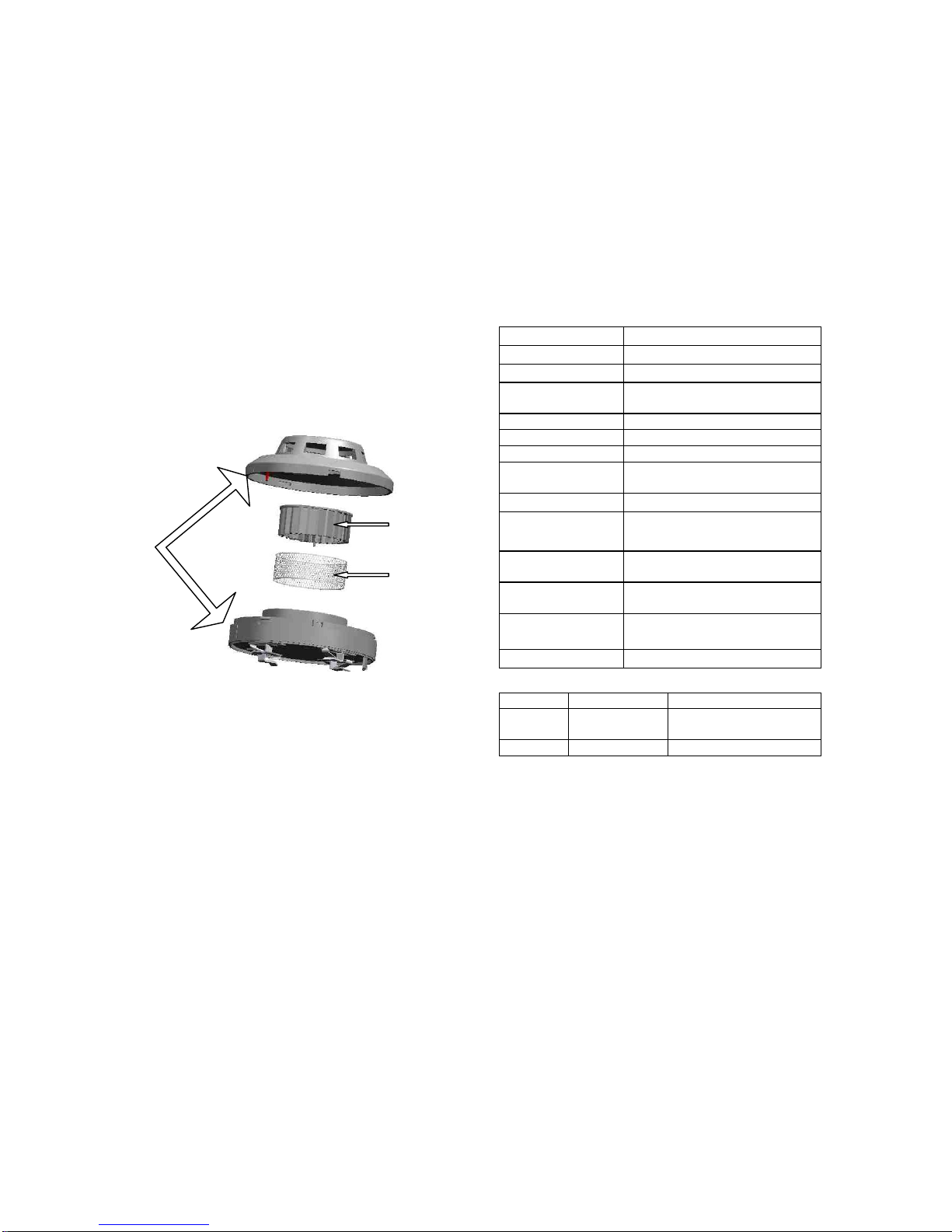
3. Remove the detector from base. Use straight
screwdriver to prize the top cover through three small
grooves. Use a vacuum cleaner or cleaned,
compressed air to remove dust and debris from the
insect guard. If the dust is too much to clean up, you
can remove the sensing chamber and pull the insect
guard to clean or replace. Use a vacuum cleaner or
cleaned, compressed air to remove dust and debris
from the sensing chamber. Reinstall the sensing
chamber and insect guard properly. Aligning the marks
on enclosure, install the top cover again. Refer to
Fig.4.
Fig. 4
4. The detector should be tested again after
re-installed.
Cautions
1. Dust cover can’t be removed until the project is
plunged. Protect the dust cover for the future use.
2. Dust cover provides limited protection against
airborne dust particles. So, remove the detector prior
to heavy remodeling or construction and inform the
proper authority.
3. Be careful not to damage the detector in
maintenance.
4. The smoke detector may not sense fire that where
smoke cannot reach it, such as in chimneys, in walls,
on roofs, or on the other side of closed doors.
5. The detector cannot monitor the place beyond
protection area.
6. The detector may not warn you about fires caused
by insufficient safety measures, violent explosions,
leaking gas, improper storage of flammable materials
like diluents and other safety hazards, arson or
children playing with fire.
7. The alarm of a smoke detector used in high
velocity environment will be delayed due to dilution of
smoke by frequent and fast airflow.
8. The smoke detector cannot last forever. In order to
keep the detector working in good condition, please
maintain the equipment continuously according to
recommendations from manufacturers and relative
nation codes and laws.
9. The detectors must be tested regularly, at least
once a year.
Specification
Operating Voltage
Loop 24V(16V~28V)
Standby Current
≤0.8mA
Alarm Current
≤2.0mA
Indicators
Red, flash in normal, illuminate
when alarming
Programming Mode
Electronically addressed
Code Range
One address within 1~242
Wiring
Two-wire, polarity-insensitive
Ambient
Temperature
32℉(0℃)~100℉(+37.8℃)
Relative Humidity
≤95%, non condensing
Ingress Protection
Rating
IP23
Material and Color
of the Enclosure
ABS, White (RAL 9010)
Dimensions
Diameter 100mm
Height: 43mm (without base)
Mounting Hole
Distance
45mm~75mm
Weight
About 120g
Accessories and Tools
Model
Name
Remark
P-9910B
Hand Held
Programmer
Order separately
DZ-03
Base
Order separately
Limited Warranty
GST warrants that the product will be free of charge
for repairing or replacing from defects in design,
materials and workmanship during the warranty period.
This warranty does not cover any product that is found
to have been improperly installed or used in any way
not in accordance with the instructions supplied with
the product. Anybody, including the agents,
distributors or employees, is not in the position to
amend the contents of this warranty. Please contact
your local distributor for products not covered by this
warranty.
Sensing
Chamber
Insect
Net
Marks on side
This Data Sheet is subject to change without notice. Please contact GST for more information or questions.
Gulf Security Technology Co., Ltd.
No. 80, Changjiang East Road, QETDZ, Qinhuangdao, Hebei, P. R. China 066004
Tel: +86 (0) 335 8502434 Fax: +86 (0) 335 8502532
service.gst@fs.utc.com www.gst.com.cn
 Loading...