

Page 1

GST-RP16
Conventional Repeater Panel
Installation and Operation Manual
(Issue 1.03, Jan 2014)
Page 2

GST-RP16 Conventional Repeater Panel
Installation and Operation Manual
CONTENTS
I General ................................................................................................................ 1
II Features ............................................................................................................... 1
III Technical Specifications ....................................................................................... 1
IV Structure and Operation Principle ........................................................................ 1
V Mounting and Commission .................................................................................. 2
VI Operations ............................................................................................................ 3
VII Troubleshooting ................................................................................................... 3
VIII Cautions ............................................................................................................... 4
Page 3

GST-RP16 Conventional Repeater Panel
Installation and Operation Manual
Page 1
I General
GST-RP16 Conventional Repeater Panel (hereinafter called GST-RP16), the
supporting product of a conventional fire alarm control panel FACP , is a type of fire
display unit used in buildings or fire control center. When the conventional FACP
receives fire signal, it will alarm and send the signal to GST-RP16. Then the GST-RP16
will indicate the alarm zone and sound to notice the people there to act accordingly.
GST-RP16 is a non-addressable repeater panel matching with GST102A, GST104A,
GST108A, and GST116A Conventional Fire Alarm Control Panel.
II Features
1. It can indicate fire signals in 16 zones separately.
2. With two fault outputs, it can show fault signals from conventional FACP.
3. It is wall-mounted, with advantages of small dimension, simple installation and
operation, good performance, high reliability, and flexible configuration etc.
III Technical Specifications
1. Display Capacity: Maximum 16 signals, 2 fault signals.
2. Wiring: Connect with conventional FACP by multi-wire (16 for fire signals and 2 for
fault signals) and two 24VDC power wires in addition.
3. Operation Environment:
Temperature: 0 +40
Relative Humidity 95%, no condensation
4. Power supply with 18VDC 28VDC, standby current 12mA, alarm current 60mA.
5. Dimension: 280mm 110mm 46mm.
IV Structure and Operation Principle
1. GST-RP16 is wall-mounted. Its appearance is shown in Fig. 1.
Fig. 1
ZONE12
MUTE
ZONE14 ZONE16ZONE 2 ZONE 4 ZONE 6 ZONE 8 ZONE10
PowerON
ZONE11ZONE 1 ZONE 3 ZONE 5 ZONE 7 ZONE 9
FAULT
FIRE
ZONE13 ZONE15
Page 4
GST-RP16 Conventional Repeater Panel
Installation and Operation Manual
Page 2
2. Front panel is shown in Fig. 2.
Fig. 2
Instructions of Key and Indicators:
Power ON This green LED is constantly lit after the power is on.
FIRE General fire alarm light. a red LED, lit when there is a fire signal.
ZONE1~ZONE16 Zone fire lights, red LEDs, lit if there are fire alarms in
corresponding zones. The flashing of an LED indicates it is the latest fire alarm.
FAULT Fault light, yellow, lit when there is a fault signal.
MUTE Pressing this key in alarm or fault state can silence the alarm sound, while
it gives another sound to indicate the mute state.
3. Operation Principle
GST-RP16 is a zonal fire display panel developed with microprocessor. It indicates
the alarm zone with LED and audio-visual signal. It connects with conventional
FACP with multi-wire, providing alarm signal after processing the data from
conventional FACP.
V Mounting and Commission
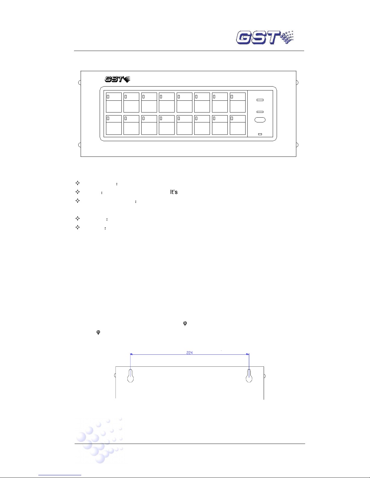
1. Mounting
GST-RP16 is wall-mounted. Drill two 5 holes on the wall as shown in Fig. 3, push
two 5 plastic expansion sleeves into the holes, then fix the back of GST-RP16
with expansion bolts and connect wires.
Fig. 3
ZONE12
MUTE
ZONE14 ZONE16ZONE 2 ZONE 4 ZONE 6 ZONE 8 ZONE10
PowerON
ZONE11ZONE 1 ZONE 3 ZONE 5 ZONE 7 ZONE 9
FAULT
FIRE
ZONE13 ZONE15
Page 5

GST-RP16 Conventional Repeater Panel
Installation and Operation Manual
Page 3
2. Terminals are shown in Fig. 4.
24V GND FAU1 FAU2
XT1
Fig. 4
24V GND: Connect with auxiliary power terminals AUX SUPPLY + - of
conventional FACP. Other 24VDC power supply can also be used, but please make
sure that the Ground of the power supply is well connected to the - of AUX
SUPPLY (+, -) of conventional FACP.
FIRE1 FIRE16: Connect with zonal indication terminals Z1~Z8 of REPEATER
OUTPUT of conventional FACP.
FAU1 FAU2: Connect with fault terminal FLT of REPEATER OUTPUT of
conventional FACP.
Wiring: 227 IEC 05 cables for signal input and power supply, cross section is
1.0mm2.
3. Commission: GST-RP16 carries out self-test when power is on and all LEDs are lit.
The buzzer alarms fire. After self-test, Power ON LED is lit, other LEDs are off, and
the buzzer doesn t sound.
4. Keep chassis well grounded to ensure stable operation.
VI Operations
1. Put the jumper X1 ON .
2. In monitoring state, only Power ON LED is lit.
3. When there is a fire alarm, the FIRE LED is lit, and the zonal FIRE LED
corresponding to conventional FACP is also lit. If it is the latest fire, relevant zonal
FIRE LED flashes every 0.25s and GST-RP16 sounds every 0.25s.
4. FAULT LED is lit when there is a fault. The buzzer provides a fault sound (0.5s on,
4.5s off) if no fire alarm comes. If a fire condition occurs, the buzzer then gives fire
alarm sound every 0.25s.
5. When MUTE is pressed, fire or fault sound will be silenced, and another sound
(0.5s on, 9.5s off) indicates the mute state. If there is a fire or fault signal again, it
will sound again.
VII Troubleshooting
Common problems and repair methods are shown in Table1 below.
Page 6

GST-RP16 Conventional Repeater Panel
Installation and Operation Manual
Page 4
Table1
Number Problem Reasons Repair Methods
1
The device
be
started up.
a. Jumper X1 is not at ON
end.
b. No 5V
a. Put X1 to ON .
b. Check 7805 and its
periphery circuit
2
No self-
test
or display
wrongly
after
power-on
a. Power supply is
abnormal.
b. Connection with display
panel is loose.
c. LED is damaged.
d. Transistor oscillator or
main CPU damaged
a. Check 24V power supply
b. Check wiring
c. Replace the LED.
d. Check transistor oscillator or
replace main CPU
3
No dealing
with alarm
signals
a.
Connection loose in input
part.
b. Insulated optocoupler
does not work.
c. Output circuit is
damaged.
d. Transistor oscillator or
main CPU damaged.
a. Connect it in a right way.
b. Replace the optocoupler.
c. Check 74HC595 and
ULN2003
d. Check transistor oscillator or
replace main CPU
4
No sound
a. Output circuit is damaged
b. Buzzer is damaged.
a. Check 74HC595 and
ULN2003
b. Replace the buzzer.
VIII Cautions
1. Before powering up, check all cable problems, such as short circuit, open circuit
and wrong connections etc.
2. GST-RP16 is a precise electronic product and must be maintained by specific
personnel.
3. Make record on duty.
4. We take the responsibility of repairing the repeater. If any problem occurs, please
contact us in time. The users will be responsible for any result from repairing
GST-RP16 themselves.
 Loading...