

Page 1
Page 2

GST-NRP00/GST-NRP00-HU/GST-NRP00-PT
Network Repeater Panel Installation and Operation Manual
CONTENTS
Installation Precautions ...............................................................................................1
Chapter 1 Product Introduction...................................................................................2
Chapter 2 Technical Specifications ............................................................................3
2.1 Electrical Specifications.........................................................................................3
2.2 Communication Loop Parameters ........................................................................3
2.3 Dimensions............................................................................................................3
Chapter 3 Structure ......................................................................................................4
3.1 Appearance and Internal Structure .......................................................................4
3.1.1 Description of LEDs ..................................................................................4
3.1.2 Description of Keys...................................................................................5
3.2 Configuration.........................................................................................................6
3.2.1 Default Configuration ................................................................................6
3.2.2 Optional Components ...............................................................................6
Chapter 4 Installation ...................................................................................................7
4.1 Configuration Inspection .......................................................................................7
4.2 Installing the Cabinet.............................................................................................7
4.3 Start-up Check.......................................................................................................7
4.4 Connections of Field Devices ...............................................................................8
4.4.1 Connection of Power Supply ....................................................................8
4.4.2 Connection of Communication Loop.........................................................8
Chapter 5 Display and Disposal of System Information ..........................................9
5.1 Normal Information................................................................................................9
5.2 Fire Alarm ..............................................................................................................9
5.2.1 Fire Alarm Screen .....................................................................................9
5.2.2 Disposal of Fire Alarm Signal..................................................................10
5.3 Fault.....................................................................................................................10
5.3.1 Fault Indication........................................................................................10
5.3.2 Disposal of Fault Message......................................................................12
5.4 Rules for Message Display .................................................................................12
5.5 Rules for Sound Indication..................................................................................12
Chapter 6 Description of System Operation............................................................13
6.1 Keypad ................................................................................................................13
6.1.1 Keypad Functions ...................................................................................13
6.1.2 Methods of Data Input.............................................................................13
6.1.3 Unlocking and Locking the Keypad ........................................................13
6.2 User Operation Instruction (No Password Requirement) ...................................14
6.2.1 Changing Time Display...........................................................................14
6.2.2 Browsing Messages................................................................................14
6.2.3 Mute ........................................................................................................16
6.3 Instructions for Operator (Operator Password Required)...................................17
6.3.1 Resetting the System..............................................................................17
6.3.2 Checking All Visual and Audible Indications ...........................................17
6.3.3 Silence.....................................................................................................17
6.3.4 Evacuation ..............................................................................................17
6.3.5 Disable/Enable........................................................................................17
Page I
Page 3

GST-NRP00/GST-NRP00-HU/GST-NRP00-PT
Network Repeater Panel Installation and Operation Manual
6.3.6 User Mode...............................................................................................19
6.4 Instructions for System Administrator (Manager Password Required)...............20
6.4.1 Modifying System Time...........................................................................21
6.4.2 Modifying Password................................................................................21
6.4.3 Network Setup.........................................................................................22
6.4.4 Setting Zone Start Number .....................................................................23
6.4.5 Initialization of System ............................................................................23
Chapter 7 Troubleshooter..........................................................................................24
Appendix 1 Internal Connection Diagram................................................................25
Appendix 2 Device Type List .....................................................................................27
Appendix 3 Operation Menu ......................................................................................29
Page II
Page 4

GST-NRP00/GST-NRP00-HU/GST-NRP00-PT
Network Repeater Panel Installation and Operation Manual
Installation Precautions
Adherence to the following will aid in problem-free installation with long-term reliability:
Do not attempt to install, service, or operate this unit until this manual is read and
understood.
This equipment must be installed in accordance with these instructions and the
appropriate national, regional and local regulations specific to the country and
location of the installation. Consult with the appropriate Authority Having
Jurisdiction (AHJ) for confirmation of the requirements.
It shall only be installed and serviced by trained specialist.
Disconnect all sources of power before servicing.
Page 1
Page 5

GST-NRP00/GST-NRP00-HU/GST-NRP00-PT
Network Repeater Panel Installation and Operation Manual
Chapter 1 Product Introduction
GST-NRP00/GST-NRP00-HU/GST-NRP00-PT Network Repeater Panel is simple
installation, operation, and easy maintenance. It is used in fire alarm system with the
following features:
1 The LCD can display 8 lines in total and 18 characters each line, assisting the 15
LEDs to display important information.
2 The memory does not lose data even if power supply is accidentally removed.
3 RS485 interface enables networking.
Page 2
Page 6
GST-NRP00/GST-NRP00-HU/GST-NRP00-PT
Network Repeater Panel Installation and Operation Manual
Chapter 2 Technical Specifications
2.1 Electrical Specifications
Voltage: 20VDC 27VDC
Current is less than 350mA normally and less than 500mA in fire condition.
Standby power consumption does not exceed 9W and maximum power
consumption does not exceed 13W.
2.2 Communication Loop Parameters
2 channels of RS485 interface.
Transmission media: twisted pair.
Communication distance: less than 1200m.
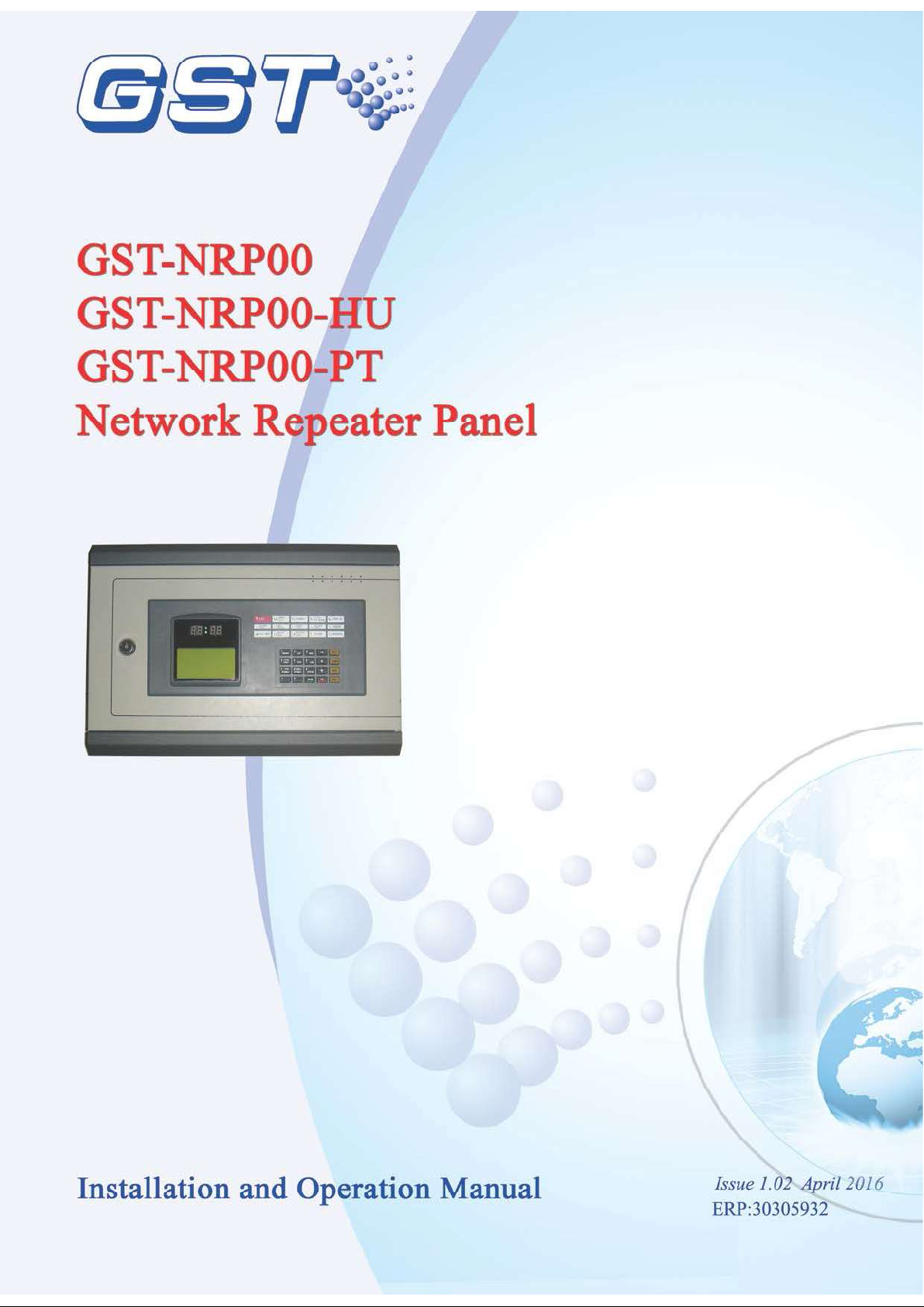
2.3 Dimensions
The dimensions of the repeater panel is 390mm×270mm×100mm (L x H x W) as shown
in Fig. 2-1.
390
100
75
Fig. 2-1
Page 3
Page 7
GST-NRP00/GST-NRP00-HU/GST-NRP00-PT
Network Repeater Panel Installation and Operation Manual
Chapter 3 Structure
3.1 Appearance and Internal Structure
The network repeater panel is flush mounted. Its appearance and internal structure are
shown in Fig. 3-1 and 3-2.
1
3
2
4
Fig. 3-1
1 Clock 2 LCD 3 Indicators 4 Keypad
Fig. 3-2
1 Main board 2 Switch board 3 LCD 4 Network board 5 Speaker
6 DC-DC Power supply 7 Terminal board
3.1.1 Description of LEDs
FIRE: Red. It illuminates when the repeater panel receives a fire alarm message
from fire alarm control panels (FACP) in network. After fire condition is removed,
the fire status can only be cleared by pressing RESET key, and this LED goes out
simultaneously.
COMMON FAULT: Yellow. It illuminates when it receives fault messages from
FACPs in network or when there is fault with itself. It goes out automatically after
Page 4
Page 8

GST-NRP00/GST-NRP00-HU/GST-NRP00-PT
Network Repeater Panel Installation and Operation Manual
the fault condition is removed.
DISABLE: Yellow. It illuminates when the repeater panel receives, from FACPs in
network, disabled messages of connected devices, FP.E. output or SOUNDER
CIRCUIT OUTPUT. It goes out when such status is canceled.
SYSTEM FAULT: Yellow. It illuminates if the program encounters a dead halt. After
the system is rebooted, only by pressing RESET, can system fault be cleared, and
this LED goes out.
PRE-ALARM: Red. It illuminates if there is pre-alarm message.
POWER ON: Green. It illuminates when system power is normal.
POWER FAULT: Yellow. It illuminates when the repeater panel receives message
of fault with FACPs in network. After the fault is cleared, it will go out.
F.P.E. FLT/DISABLE: Yellow. It flashes when the repeater panel receives message
of fault with F.P.E. output and illuminates steadily after the F.P.E. is disabled. It
goes out after the fault and disabled conditions are cleared.
SOUNDER FLT: Yellow. It illuminates when the repeater panel receives message of
fault with the SOUNDER CIRCUIT OUTPUT of FACPs in network. It goes out
automatically after the fault is cleared.
SOUNDER DISABLE: Yellow. It illuminates steadily after the SOUNDER CIRCUIT
OUTPUT of FACPs in network is disabled. It goes out automatically after the
disabled condition is cleared.
TEST MODE: Yellow. It illuminates when the repeater panel is under commission.
SILENCE: Yellow. It illuminate after SILENCE key is pressed, and goes out when
RESET key or EVAC key is pressed.
EVAC: Red. It illuminates after EVAC key is pressed and goes out when RESET or
SILENCE key is pressed.
3.1.2 Description of Keys
SYSTEM: System set-up key (manager password required), used for setting
system time, modifying operator password and manager password, setting network
system, and system initialization.
TEST: Self-test key (operator password required). Pressing this key in normal
standby state can self-test the audible and visual indication.
MODE: Mode setting key (operator password required). Pressing this key can set
the LCD contrast, message display modes, manually start device and manually
stop device.
TAB: For switching different type of messages in display screen; for moving the
cursor under input screen.
RESET: Resetting the repeater panel or FACPs in network (operator password
required).
BROWSE: Browsing network information.
Page 5
Page 9

GST-NRP00/GST-NRP00-HU/GST-NRP00-PT
Network Repeater Panel Installation and Operation Manual
LOG: Viewing history record.
MUTE: Pressing this key can silence the sound of FACPs and GST-NRP01
repeater panels in network.
VIEW FAULT: If the repeater panel is not displaying fault messages, pressing this
key can view fault messages.
LOCK: Locking the keypad when it is unlocked.
, : Scrolling among more than one piece of displayed messages.
ESC: Canceling or quitting the operating menu. If it’s pressed while the repeater
panel is displaying messages, it will resume to display messages of the highest
level.
VIEW DISABLE: If the screen is not displaying disabled messages, pressing this
key can view the disabled messages.
ENTER: Confirming inputs to be valid. In normal standby state, pressing it can
toggle the clock display between month/day mode and hour/minute mode.
SILENCE Pressing it can silence the sounders and close the output of alarm
bell.
EVAC: Pressing this key can start all sounders and bells in the system to evacuate
people.
3.2 Configuration
3.2.1 Default Configuration
A standard repeater panel consists of main board, power converter module and display
and operation part.
Main board
Main board is the core of the repeater panel, which contains CPU and interfaces to
other main parts.
Power converter module
The power converter module is used for converting the power supply from 24VDC
to 5VDC.
Display and operation part
This part is used to indicate and display different status of the system, and enables
relative operations through keypad (browsing, setting and etc).
3.2.2 Optional Components
Network Card (P-9940A P-9960A P-9960)
The network card is used for connecting GST series FACPs into network. Refer to
Appendix 1 for wiring.
Page 6
Page 10
GST-NRP00/GST-NRP00-HU/GST-NRP00-PT
Network Repeater Panel Installation and Operation Manual
Chapter 4 Installation
4.1 Configuration Inspection
Before installation, check the following items:
Engineering Configuration
Check the configuration according to packing list. The main items to be examined are:
installation and operation manual, keys to the repeater panel, etc.
Internal Configurations and Interconnections
All internal parts have been connected (including optional units ordered) before the
repeater panel leaves the factory. Therefore, you can mainly check the connection
among parts, including the connection between main board and power converter board,
switch board and network board, the connection of power converter board, network
board and terminal board, and of speaker and main board etc. Please refer to Appendix
1 for the internal connection diagram.
4.2 Installing the Cabinet
Dimension of the cabinet is shown in Fig. 4-1.
Ambient conditions for installation of the repeater panel:
Temperature: 0 40
Relative humidity: 95 , non-condensing
360
300
330
Fig. 4-1
100
75
4.3 Start-up Check
After installation, apply power to it as shown in Fig. 4-2. Turn on the power supply and
check if the repeater panel can self-test. The procedures are as follows.
Check if the digital displays showing time are illuminated one by one.
Check if the LCD showing system messages such as fire alarm is illuminated.
Check if the LEDs showing the state of system can be illuminated one by one.
Page 7
Page 11

GST-NRP00/GST-NRP00-HU/GST-NRP00-PT
Network Repeater Panel Installation and Operation Manual
Check if the speaker can give two kinds of loud alarm sounds.
4.4 Connections of Field Devices
4.4.1 Connection of Power Supply
The input power for the repeater panel is non-polarized 24V, which is converted to 5V by
a DC-DC converter module.
4.4.2 Connection of Communication Loop
The connection of communication loop is shown in Fig. 4-2, in which any “Fire Panel n
(n=2 32)” can be replaced with a repeater panel.
Fig. 4-2
Page 8
Page 12

GST-NRP00/GST-NRP00-HU/GST-NRP00-PT
001 0f 006 !FIRE! 05:25
Network Repeater Panel Installation and Operation Manual
Chapter 5 Display and Disposal of System Information
The network repeater panel can be started after installation. Turn on the power switch,
the repeater panel starts self-test and then enters normal standby state. The system will
display properly if it is in normal state, otherwise it will display abnormal information.
5.1 Normal Information
The normal display is shown in Fig. 5-1, which means the system is in working state.
Then only POWER ON LED lights.
GST CO., LTD.
SYSTEM ALL NORMAL
Fig. 5-1
Fig. 5-2 shows the system is in normal operation but with disabled devices. Pressing
VIEW DISABLE can browse these devices.
GST CO., LTD.
SYSTEM NORMAL
WITH DISABLE
Software V*.*
Fig. 5-2
Software
version number
5.2 Fire Alarm
5.2.1 Fire Alarm Screen
FIRE LED is lit and fire alarm signal is displayed from the networked FACP when there
is fire. It is shown as in Fig 5-3.
Zone:001 030MCP
Device-30
------------------------------------Last !Fire! Zone:003
Zone 3 Device-066
Fig. 5-3
Page 9
Page 13

GST-NRP00/GST-NRP00-HU/GST-NRP00-PT
Network Repeater Panel Installation and Operation Manual
001 0f 006 !FIRE! 05:25 // There are six devices with fire alarm signals, and this is
the first.
Zone: 001 030MCP // The number of zone with fire alarm and type and
address of the device in fire alarm.
Device-30 // Description of device in fire alarm.
Last !Fire! Zone:003 // Zone number of the last fire alarm.
Zone3 Device-066 // Description of the device and of that zone with the last fire
alarm.
5.2.2 Disposal of Fire Alarm Signal
When fire alarm occurs, first find out the location according to the information shown on
the repeater panel and verify if there is a real fire.
If it’s a real fire, please take corresponding measures as outlined below.
Step 1: Evacuate people.
Step 2: Call the fire department.
Step 3: Initiate extinguishers.
If it is a false alarm, please take the following measures.
Step 1: Press SILENCE to stop the sound.
Step 2: Remove the causes of the false alarm.
Step 3: Press RESET to make the FACP back to the normal state. If the device still
gives false alarm, disable it using a FACP in network and inform the installer or
manufacturer for repair.
5.3 Fault
5.3.1 Fault Indication
In case of fault, the repeater panel and FACPs in network display the fault message
simultaneously and light corresponding LED.
Mains fault: If the AC power of networked FACPs is down, the repeater panel
reports AC fault, and
Lights COMMON FAULT and POWER FAULT LED.
The LCD displays “AC FAULT”.
Generates fault sound.
Battery fault: The repeater panel reports battery fault if the battery voltage is lower
than 18.9V, and would:
Light COMMON FAULT and POWER FAULT LED.
The LCD displays “BATTERY FAULT”.
Page 10
Page 14

GST-NRP00/GST-NRP00-HU/GST-NRP00-PT
Network Repeater Panel Installation and Operation Manual
Generates fault sound.
System fault: The repeater panel would report system fault if its control CPU and
circuits are in fault and it cannot work normally.
It lights the COMMON FAULT and SYSTEM FAULT LED.
There is no display on the LCD.
The repeater panel generates continuous alarm sound.
The repeater panel cannot monitor fire alarm.
The keypad cannot be used.
If system fault indication remains for less than 5 seconds, the repeater panel
will assume that this is not a true fault and automatically clear the LED and
sounder indication and return to normal monitor state. If system fault
indication remains for more than 5 seconds, the repeater panel will then
interpret it as a genuine fault and the LCD displays “System fault must be
reset manually. System time must be reset.” after it’s cleared. You need to
press RESET key to clear the fault indication and reset system time.
Keypad fault: The repeater panel reports keypad fault if its keypad circuit is in fault,
and
Lights the COMMON FAULT and SYSTEM FAULT LED.
The LCD displays “Key fault”.
Generates continuous alarm sound.
The keypad cannot be used.
The repeater panel can monitor fire alarm.
The repeater panel can reset automatically after the fault is removed.
Periphery device fault: If there is trouble with one of the periphery devices of the
networked FACP, the repeater panel reports fault with it, and
Lights the COMMON FAULT LED.
Generates fault sound.
The LCD displays the fault message of the net device. The fault screen is as in
Fig. 5-4.
001 0f 004FAULT10:18
Zone:003-011Optical
Fig. 5-4
Page 11
Page 15

GST-NRP00/GST-NRP00-HU/GST-NRP00-PT
Network Repeater Panel Installation and Operation Manual
001 0f 004 FAULT10:18 // There are four devices reporting fault, and this is the
first.
Zone:003-011Optical // The number of the zone with the fault message, the
address and type of the device with the fault message.
5.3.2 Disposal of Fault Message
There are two kinds of fault message. One is system fault, like AC fault, battery fault,
and loop fault. The other is field device fault, like fault with detectors and modules etc.
If the Networked FACPs are powered by battery for longer time than its capacity,
the repeater panel will shut down to protect the battery. Please charge the battery
in time to avoid any possible damage to it.
If it is system fault, please check and repair in time. If the repeater panel needs to
be shut down, please make detailed notes.
If it is field device fault, please repair it in time. You can disable it if the fault can’t be
cleared for some reason, and enable it when the fault is removed.
5.4 Rules for Message Display
If there are multiple messages in the system, they will be displayed in the following order:
fire alarm, action, fault, start, disable.
1 The earliest fire alarm is displayed in priority. The latest action, fault, disabled
message is displayed in priority.
2 There are zone and loop display modes for fire alarm, fault, and disabled messages.
And start and action only has loop display mode.
3 In any display mode, the system will return to displaying of the highest priority if
there is no operation within 20s (15s 30s).
5.5 Rules for Sound Indication
The repeater panel will sound to indicate fire alarm or fault messages.
The repeater panel gives fire engine sound when fire alarm occurs.
The repeater panel gives ambulance sound when fault occurs
The repeater panel will give sound of higher priority if two types of event occur
simultaneously.
Page 12
Page 16

GST-NRP00/GST-NRP00-HU/GST-NRP00-PT
Network Repeater Panel Installation and Operation Manual
Chapter 6 Description of System Operation
6.1 Keypad
6.1.1 Keypad Functions
Most of the keys have double functions. Lower mark is a character and upper mark is a
command that is only activated in monitoring state. Most function keys are controlled by
password. The characters are only active after entering the menu. Pressing ESC will
return to previous level of the menu.
6.1.2 Methods of Data Input
Pressing a character key, all characters disappear, and the display shows the newly
input one. The cursor will indicate the next input position (The cursor always indicates
the position of the next to input, and returns to the first character after completion of a
line). Pressing or , to move the cursor to modify any character.
Pressing TAB, the highlight moves to the next position and returns to the first after the
last position. Wherever the cursor is, Pressing ENTER key, all the input data will be
saved.
If there is no keypad operation for over 1 minute, the system will exit present state
without saving the input data.
6.1.3 Unlocking and Locking the Keypad
Unlocking the Keypad
The repeater panel is locked by default when powering up. If some operations are
needed, the LCD will display a screen requiring proper password. Inputting the correct
password and pressing ENTER, you can continue to operate as the keypad is unlocked.
See Fig. 6-1.
GST CO., LTD.
Please Input Password
********
8 digits
Fig. 6-1
Locking the Keypad
The keypad shall be locked after operations are finished or personnel on duty leave.
Pressing LOCK, the screen will display “Press ENTER confirm” like in Fig. 6-2.
Pressing ENTER, the keypad is locked. You will have to input password again to unlock
the keypad for any new operation.
Page 13
Page 17

GST-NRP00/GST-NRP00-HU/GST-NRP00-PT
History Record
Network Repeater Panel Installation and Operation Manual
GST CO., LTD.
Press ENTER confirm
Fig. 6-2
6.2 User Operation Instruction (No Password Requirement)
6.2.1 Changing Time Display
The clock is usually displayed in hour and minute. In normal monitoring state, pressing
ENTER, month and date are displayed. Pressing ENTER again or after a minute, hour
and minute are displayed again.
6.2.2 Browsing Messages
6.2.2.1 Turning pages
You can look through information one by one by pressing and .
6.2.2.2 Browsing more than one piece of message
The current information is highlighted when there is more than one piece of message on
the LCD. You can view details of this item by pressing ENTER or exit by pressing ESC.
6.2.2.3 Browsing registered devices
Pressing BROWSE can view network devices.
6.2.2.4 Browsing history log
Pressing LOG, the repeater panel enters the state of browsing history record. Using
and , you can browse every item, the screen is shown in Fig. 6-3.
NO. 200
! FIRE!
TIME: 10:23 14/08
Zone: Name
121 Optical
Fig. 6-3
NO. 200 // The two hundredth history log
Page 14
Page 18

GST-NRP00/GST-NRP00-HU/GST-NRP00-PT
Network Repeater Panel Installation and Operation Manual
! FIRE! // Fire alarm message
TIME: 10:23 14/08 // Date and time of the event
Zone: Name // Zone number, zone name
121 Optical // Device address and type
6.2.2.5 Browsing fault messages
You can view fault messages by pressing VIEW FAULT when the screen is displaying
non-fault messages. The display varies by the type of fault messages. Please refer to
Section 5.3.
6.2.2.6 Browsing disable messages
You can view disable messages by pressing VIEW DISABLE when the screen is
displaying non-disable messages. The screen of loop mode is shown in Fig. 6-4 and
the screen for zone mode is shown in Fig. 6-5 and Fig. 6-6.
001 of 003
Disable
12:01
Zone 001 004Sounder
Office1
Fig. 6-4
001 of 003 Disable 12:01 //There are three disabled devices in the system and this
is the first.
Zone: 001 004Sounder //The zone number, address and device type of the
disabled device.
Office1 //Description message of the disabled device.
001 of 002
Disable
12:01
Zone 005 Z-005
029/029
Zone Fully Disabled
Fig. 6-5
001 of 002 Disable 12:01 // There are devices from 2 zones that are disabled, and
this is the first zone.
Zone: 005 Z-005 // Zone number and description message of the disabled
zone.
029/029 // All 29 devices of the current zone are disabled.
Page 15
Page 19

GST-NRP00/GST-NRP00-HU/GST-NRP00-PT
Network Repeater Panel Installation and Operation Manual
Zone Fully Disabled // Current zone are completely disabled.
002 of 002
Disable
12:01
Zone 006 Z-006
016/030
Zone Part Disabled
Fig. 6-6
002 of 002
Disable
12:01 // There are devices from 2 zones that are disabled and
this is the second zone.
Zone: 006 Z-006 // Zone number and description message of the disabled zone.
016/030 //There are 16 disabled devices in all 30 devices of the current zone.
Zone Part Disabled // The zone is partially disabled
6.2.2.7 Browsing action messages
You can view action messages by pressing TAB when the screen is displaying
non-action messages. The screen is shown in Fig. 6-7.
001 of 004 ACTION 12:15
Zone:001-004Sounder
Office1
Fig. 6-7
001 of 004 ACTION 12:15 // There are 4 action messages in the system and this is
the first, time 12:15.
Zone:001-004Sounder //The zone number, device address and device of the
device in action.
Office1 //Description message of the device in action.
6.2.3 Mute
Pressing MUTE can stop the speaker of this repeater panel, networked FACPs and
other repeater panels; pressing MUTE again, they are still in mute state. They will sound
by priority when one or more new event(s) appear(s), which can be silenced by further
pressing of Mute key.
Page 16
Page 20

GST-NRP00/GST-NRP00-HU/GST-NRP00-PT
Network Repeater Panel Installation and Operation Manual
6.3 Instructions for Operator (Operator Password Required)
6.3.1 Resetting the System
Pressing RESET can reset the repeater panel and all the control modules, outputs and
detectors connected to the network FACPs, but will leave the disabled devices as they
are. The LCD displays “RESET IN SYSTEM”. LEDs will be turned off (Except for
“POWER ON” LED). “RESET” information will be written into running log. If there is still
fire alarm, fault and action not acknowledged after pressing the RESET key, the
repeater panel will remain relative sound indications. If all messages have been
acknowledged by pressing RESET key, the system returns to normal display state.
6.3.2 Checking All Visual and Audible Indications
In normal monitoring state, you can check all visual and audible indications of the
repeater panel by pressing TEST.
6.3.3 Silence
Pressing SILENCE can silence the sounders and bells.
6.3.4 Evacuation
Pressing EVAC can manually start all sounders and bell to evacuate people.
6.3.5 Disable/Enable
Devices are disabled when a device is fault and the fault cannot be removed
immediately. This device can then be temporarily disabled and enabled after it’s
repaired.
Pressing ENABLE/DISABLE, the screen will be shown as in Fig. 6-8.
*Disable/Enable*
1 Disable Devices
2 Enable Devices
3 Delete Net Disable
Fig. 6-8
In the screen as in Fig. 6-8, inputting number 1, you can enter device disable screen as
shown in Fig. 6-9.
Disable
Z000C000T00NoDefine
Fig. 6-9
Page 17
Page 21

GST-NRP00/GST-NRP00-HU/GST-NRP00-PT
Network Repeater Panel Installation and Operation Manual
In the above screen, you can operate as follows:
Enter 3-digit zone number or “*” at the cursor position after letter “Z”.
Enter 3-digit device code or “*” at the cursor position after letter “C”.
Enter 2-digit device type or “*” at the cursor position after letter “T”.
Example 1, in order to disable a photoelectric detector whose device code is 001 in
Zone 1, you need to input in sequence the zone number 001, device code 001 and
device type 03.
Example 2, in order to disable all alarm devices with device type between 01 and 11 in
Zone 1, you need to input in sequence the zone number 001, device code *** and
device type **. Please note that the asterisk mark “**”is not allowed to use for action
devices whose device type between 12 and 65.
In the screen as in Fig. 6-8, inputting number 2, you can enter device enable screen as
shown in Fig. 6-10. In this screen, you can enable the device. Refer to description below
Fig. 6-9 for operations.
Enable
Z000C000T00NoDefine
Fig. 6-10
In the screen as in Fig. 6-8, inputting number 3, you can enter Delete Net Disable
screen as shown in Fig. 6-11. In this screen, inputting number of disable information,
and pressing Enter key, the disable message from connected FACP can be deleted.
Delete Net Disable
Number : 000
Fig. 6-11
Page 18
Page 22

GST-NRP00/GST-NRP00-HU/GST-NRP00-PT
Network Repeater Panel Installation and Operation Manual
6.3.6 User Mode
Pressing MODE key can enter user mode setup screen as shown in Fig. 6-12.
*User Mode*
1 LCD Contrast
2 Browse Mode
3 Start Devices
4 Stop Devices
Fig. 6-12
In the above screen, you can operate as follows:
Entering 1 in Fig. 6-12 will enter the screen for setting up LCD contrast, as shown in
Fig. 6-13. In this screen, “ ” and “ ”are used to adjust LCD contrast.
GST CO., LTD.
*LCD Contrast*
048
Fig. 6-13
Entering 2 in the screen of Fig. 6-12 will enter the screen for setting up display
mode, as shown in Fig. 6-14. In this screen, choosing “1 Zone Mode” can browse
system messages by zone, and choosing “2 Loop Mode” can browse by loop.
Browse Mode
1 Zone Mode
2 Loop Mode
Fig. 6-14
Page 19
Page 23

GST-NRP00/GST-NRP00-HU/GST-NRP00-PT
*System Mode*
Network Repeater Panel Installation and Operation Manual
Entering 3 in the screen of Fig. 6-12 will enter the screen for manual start of system
devices, as shown in Fig. 6-15. The FACP provides two modes, starting a single
device and starting multiple devices. The method of operation and the use of “*” is
the same as disablement operation.
Start-up
Z000C000T00NoDefine
Fig. 6-15
Entering 4 in the screen of Fig. 6-12 will enter the screen for manual stop of loop
devices, as shown in Fig. 6-16. The method for stopping a device is the same as
starting a device.
Stop EQ
Z000C000T00NoDefine
Fig. 6-16
6.4 Instructions for System Administrator (Manager Password
Required)
Press SYSTEM to enter the system setting screen. The screen is shown in Fig. 6-17.
1 Time/Date
2 Password Change
3 Network Setup
4 Zone Start Number
5 Initialize System
Fig. 6-17
Page 20
Page 24

GST-NRP00/GST-NRP00-HU/GST-NRP00-PT
* Time/Date Setting*
Network Repeater Panel Installation and Operation Manual
6.4.1 Modifying System Time
Inputting “1” in the screen of Fig. 6-17, the system enters Time/Date setting screen. See
Fig. 6-18. After inputting time on highlighted position and pressing TAB, the next cell is
highlighted. Press ENTER to save the modification.
Please Input
Day Month Year
04 01 05
Hour Minute Sec
11 39 55
Fig. 6-18
6.4.2 Modifying Password
Inputting “2” on the screen in Fig. 6-17, the system enters the window of password
modification. See Fig. 6-19. Now the passwords can be modified.
Password Change
1. Operator Password
2. Manager Password
Fig. 6-19
Inputting “1” or “2” to choose password to be modified, the system enters the window in
Fig. 6-20.
Modify Password
Input password
********
Fig. 6-20
After the password (8 digits from 0-9) is input, the LCD will display the screen shown in
Fig. 6-21, requesting to confirm password.
Page 21
Page 25

GST-NRP00/GST-NRP00-HU/GST-NRP00-PT
Network Repeater Panel Installation and Operation Manual
Modify Password
Confirm Password
********
Fig. 6-21
Input password again. If the two passwords are the same, the LCD will display the
window shown in Fig. 6-22, meaning the modification is successful.
GST CO., LTD.
Success
Fig. 6-22
6.4.3 Network Setup
Inputting “3” on the screen in Fig. 6-17, the screen shown in Fig. 6-23 will be displayed.
*NETWORK SETUP*
1. NET Local Address
2. NET Event Display
Fig. 6-23
In the above screen,
You can set the repeater panel’s network address by entering number 1, as shown
in Fig. 6-24.
*Net Local Address*
Please Input: 01
Range 2-32
Fig. 6-24
Page 22
Page 26

GST-NRP00/GST-NRP00-HU/GST-NRP00-PT
Network Repeater Panel Installation and Operation Manual
You can set the repeater panel to display network message or not by entering
number 2, as shown in Fig. 6-25.
*Display Mode*
1 Disable
2 Enable
Fig. 6-25
6.4.4 Setting Zone Start Number
Inputting “4” on the screen in Fig. 6-17, the screen shown in Fig. 6-26 will be displayed.
The zone start number of the FACP can be set up.
*Zone Start Number*
Please Input 001
Fig. 6-26
6.4.5 Initialization of System
Input “5” on the screen shown in Fig. 6-17, you can initialize system data.
Page 23
Page 27

GST-NRP00/GST-NRP00-HU/GST-NRP00-PT
Loose connection with
Network Repeater Panel Installation and Operation Manual
Chapter 7 Troubleshooter
The FACP shall only be repaired by specially trained GST technical service personnel.
Please disconnect the power before repair!
Possible off-normal conditions and their solution are listed in Table 7-1.
No. Problems Possible Causes Solutions
1 No indication on
the repeater
panel or
abnormal
indication
2 Cannot
communicate
with networked
FACPs
WEEE Information
2012/19/EU (WEEE directive): Products marked with this symbol cannot be
disposed of as unsorted municipal waste in the European Union. For proper
recycling, return this product to your local supplier upon the purchase of
equivalent new equipment, or dispose of it at designated collection points.
a. Power is abnormal
b.
switchboard.
The polarity of
communication cable
between the repeater panel
and the FACP is reversed.
a. Check the input and output of
power converter board.
b. Check the connection with
switchboard.
Correct the polarity of
communication cable.
Page 24
Page 28

GST-NRP00/GST-NRP00-HU/GST-NRP00-PT
Network Repeater Panel Installation and Operation Manual
Appendix 1 Internal Connection Diagram
B1
XT3
A1
B2
XT2
A2
D2
D1
XT1
XT16
XT15
XT14
B1
A1
B2
A2
GND
24V
XT1
B1
A1
B2
A2
+
-
Main Board MB-010
Switch Board SB-010
LCD Screen SC-200
Network Card P-9940A
Speaker SP-200
DC-DC Converter PB-010
P-9940A
Optiona l access ories
CN1 CN2
+5V
GND
XS12
X1
XS1
XS1
+5V
GND
XS6
XS3
X3
XS2XS10
X2
XP1
K
A
B
Terminal Board TB-010
B1
XT3
A1
B2
XT2
A2
D2
D1
XT1
XT16
XT15
XT14
B1
A1
B2
A2
GND
24V
XT1
CAN_L1
CAN_H1
CAN_L2
CAN_H2
XT2
+
-
Main Board MB-010
Switch Board SB-010
LCD Screen SC-200
Network Card P-9960A
Speaker SP-200
DC-DC Converter PB-010
Terminal Board TB-010
P-9960A
Optional accessories
CN1 CN2
+5V
GND
XS12
X1
XS1
XS1
+5V
GND
XS6
XS3
X3
XS2XS10
X2
XP1
K
A
B
Page 25
Page 29

GST-NRP00/GST-NRP00-HU/GST-NRP00-PT
Network Repeater Panel Installation and Operation Manual
B1
XT3
A1
B2
XT2
A2
D2
D1
XT1
XT16
XT15
XT14
B1
A1
B2
A2
GND
24V
XT1
CAN_L
CAN_H
Main Board MB-010
Switch Board SB-010
LCD Screen SC-200
Network Card P-9960
Speaker SP-200
DC-DC Converter PB-010
Terminal Board TB-010
P-9960
Optiona l access ories
+
CN1 CN2
-
XS12
+5V
GND
X1
XS6
XS3
X3
X2
XP1
K
A
B
XS1
+5V
GND
XS1
XS2XS10
Page 26
Page 30

GST-NRP00/GST-NRP00-HU/GST-NRP00-PT
Network Repeater Panel Installation and Operation Manual
Appendix 2 Device Type List
Nodefine 00 Undefined
MultiDet 01 Multi-sensor detector
Heat 02 Heat detector
Optical 03 Photoelectrical smoke detector
User Def 04 User defined device
Gas Det 05 Gas detector
Beam Det 06 Infrared beam detector
FlameDet 07 Ultraviolet flame detector
Con FACP 08 Cable heat detector
User Def 09 User defined device
Flow SW 10 Water flow indicator
MCP (BG) 11 Manual call point
SounderB 12 Fire broadcast
Sounder 13 Sounder strobe
Flasher 14 Flasher
Lift 15 Lift
Damper 16 Damper
FireDoor 17 Fire door
AHU 18 Air Conditioner
Extract 19 Smoker exhauster
BMS 20 Building management interface
VAModule 21 Voice alarm module
FTModule 22 Fire telephone
HR MCP 23 Hydrant call point
HR Pump 24 Hydrant pump
SPKR Pmp 25 Sprinkler pump
Elevator 26 Fire elevator
User Def 27 User defined device
User Def 28 User defined device
User Def 29 User defined device
User Def 30 User defined device
Trouble 31 Fault output
PSU 32 Power supply unit
User Def 33 User defined device
User Def 34 User defined device
User Def 35 User defined device
User Def 36 User defined device
Page 27
Page 31

GST-NRP00/GST-NRP00-HU/GST-NRP00-PT
Network Repeater Panel Installation and Operation Manual
User Def 37 User defined device
User Def 38 User defined device
Net Unit 39 Net unit
Repeater 40 Repeater panel
ZoneValv 41 Signal valve
Flow SW 42 Waterflow indicator
PS.DIFF 43 Foam pump
User Def 44 User defined device
User Def 45 User defined device
Gas Dump 46 Gas extinguisher start
GasAbort 47 Gas extinguisher stop
User Def 48 User defined device
User Def 49 User defined device
User Def 50 User defined device
User Def 51 User defined device
User Def 52 User defined device
Stop Mod 53 Device stop
Silence 54 Mute key
SounderA 55 Fire alarm sounder
SounderF 56 Fault sounder
Loop SW 57 Loop switch
CRTFault 58 GMC fault
Loop 59 Loop
PSU.Bat 60 Battery
PSU.AC 61 AC power
Lock 62 Control key
PART 63 Partial devices
ZoneDir 64 Zone indication
F.P.E
65 Fire protection equipment
Page 28
Page 32

GST-NRP00/GST-NRP00-HU/GST-NRP00-PT
Network Repeater Panel Installation and Operation Manual
Appendix 3 Operation Menu
Menu
BROWSE To view networked devices
LOG To view history record
SILENCE To silence the sounders and bells [Operator password
required]
EVAC To start all sounders and bells [Operator password required]
MUTE To silence the sound of FACPs and GST-NRP01 repeater panels
in network.
VIEW FAULT To view fault messages if the screen is not displaying
them.
TAB For switching different type of messages in display screen; for
moving the cursor under input screen.
TEST Audible-visible self-test key. To self-test the repeater panel in
normal standby state [Operator password required].
LOCK To lock the keypad .
or To scroll the screen when there is more than one piece of
information.
ESC To cancel an output or exit a menu. In information display state, you
can return the system to the highest level.
VIEW DISABLE To display the information of disabled devices.
MODE To set display mode
LCD Contrast To set LCD contrast
Browse Mode browsing Information
Zone Mode Zone display mode
Loop Mode Loop display mode
Start Devices manual start of loop devices
Stop Device manual stop of loop devices
ENABLE/DISABLE [operator password required]
1 Disable Devices
2 Enable Devices
3 Delete Net Disable
SYSTEM Setting system menu [Manager password required]
Time/Date Setting the system time
Password Change Setting password
Network Setup Setting network address
Initialize System To initialize the system
ENTER To confirm the input is valid. In monitoring state, press this key
to change time display between month/day and hour/minute modes.
RESET To reset the repeater panel and all the control modules, outputs
and detectors connected to the network FACPs to normal standby state
from fire alarm or fault state [Operator password required]
Page 29
 Loading...