

Page 1

1、产品型号名称,字体 Times New Roman,28 点。
2、产品 图片。
注意:
1、 GST 图标,产品名称型号,产品图片及安装使用说明
书字样左边应对齐。
2、 版本号、日期和 ERP 代码左边应与上方球体图案左边
对齐。
Page 2

D Series Smoke and Heat Detector
Application Bulletin
Content
Section 1 Overview of D Series Smoke and Heat Detectors………….…1
Section 2 Heat Detector Applications………………………………………2
Section 3 Smoke Detector Applications…………………………………….8
Section 4 Initial Installation Testing…………………………………….….12
Page I
Page 3

Model
Description
DI-M9103
Intelligent Combination 15o F(8.3℃)per minute Rate-of-Rise, and 135o F
(57℃) Fixed-Temperature Heat Detector
DI-M9102
Intelligent Photoelectric Smoke Detector
DI-M9101
Intelligent Combination Photoelectric Smoke and 135 o F (57℃)
Fixed-Temperature Heat Detector
DC-M9103
Conventional Combination 15 o F (8.3℃)per minute Rate-of-Rise, and
135 o F (57℃) Fixed-Temperature Heat Detector
DC-M9102
Conventional Photoelectric Smoke Detector
DC-M9101
Conventional Combination Photoelectric Smoke and 135 o F (57℃)
Fixed-Temperature Heat Detector
D Series Smoke and Heat Detector
Application Bulletin
Section 1 Overview of D Series Smoke and Heat Detectors
The D Series family of detectors is comprised of a variety of detection technologies to meet
the needs of the fire protection community. The detectors are constructed of a white,
high-impact polymer. All detectors plug into DB-M01mounting base. The table below lists
the available detector models.
D Series Smoke and Heat Detectors Model Description
D series of smoke and heat detectors contain their own microprocessors which allow them
to make alarm decisions based on the information collected by their sensors. Depending on
the detector, decisions may be based on the information gathered by up to two independent
sensing elements.
DI-M9103/M9102/M9101 are intelligent addressable devices. The addressing is electronic
and can be configured using a hand held tool P-9910B, refer to the P-9910B programmer
operation manual for detail information. DC-M9103/M9102/M9101 are conventional
devices.
The D series detectors provide a red LED indicate the detector’s condition. The LED
indicator displays the following states:
DI-M9101,DI-M9102 and DI-M9103:
• Normal: Red LED flashing or off, modified by the hand held tool P-9910B
• Alarm/active: Red LED steady
DC-M9101, DC-M9102 and DC-M9103:
• Normal: Red LED flashing • Alarm/active: Red LED steady
Multiple sensing technologies are incorporated into DI/DC-M9101detectors, which makes
them suitable for a wide range of applications. The tables Smoke Detector Application
section of this document list the applications suitable for the DI/DC-M9101.
Page 1
Page 4

D Series Smoke and Heat Detector
Application Bulletin
Section 2 Heat Detector Applications
WARNING: These detectors are intended for use with ionization and/or photoelectric smoke
detectors. A heat detector by itself does not provide life safety protection.
Heat detectors sense change in air temperature and initiate alarm conditions based on a
fixed-temperature point, rate of temperature rise, or amount of temperature rise above
ambient condition. Spot type heat detectors should be selected so that the rating is at least
20o F (11o C) above maximum expected ceiling temperature. Ceiling height, construction,
and ventilation play significant roles in detector performance and must be considered when
determining detector placement. The operating temperature range is 32℉to 100℉(0℃ to
37.8℃)。
2.1 Spacing of Heat Detectors
Spot type heat detector spacing ratings are based on detector installation on a flat smooth
ceiling that is 10 feet (3m) high. The listed spacing equates detector operation with the
opening of a standard sprinkler head within 2 minutes (+/- 10 seconds) located 10 feet (3m)
from the same fire. Spot type detector spacing is shown in the figure below. Detector
coverage is typically represented as a square because most structures have flat sidewalls.
Actual detector coverage covers a circle whose radius is 0.7 times the listed spacing. Since
all of the area within the detector’s circle of coverage is suitable for detecting a fire, the
shape and dimensions of the detector coverage “square” in the figure below may be
modified. Note that, although the coverage “square” is now a “rectangle,” the coverage area
remains within the overall detector circle of coverage.
Figure 1:Listed heat detector spacing
(1) Heat detector S = Listed spacing between detectors
Page 2
Page 5
D Series Smoke and Heat Detector
Application Bulletin
A spot type heat detector will cover all points located within 0.7 times the listed spacing. The
listed spacing for heat detectors is S = 50 ft. (15.3 m).
Figure 2: Detector circle of coverage
Figure 3: Alternative heat detector coverage configurations
When installed on the ceiling, spot type heat detectors must be located a minimum of 4 in.
(10 cm) from side walls. When installed on side walls, the detector must be between 4 in. (10
cm) and 12 in. (30 cm) from the ceiling, as shown below.
Page 3
Page 6

D Series Smoke and Heat Detector
Application Bulletin
Figure 4: Detector placement near ceiling or wall joints
The following figure shows the required heat detector spacing for a 200 ft.(60.9 m) by 200 ft.
(60.9 m) room with a 10 ft. (3m) ceiling. The figure shows 16 heat detectors with a required
listed spacing of S = 50 ft. (15.3 m).
Figure 5: Heat detectors spacing example
Page 4
Page 7

Ceiling height
Percent of listed spacing
Heat detector listed spacing
0 to 10 ft. (0 to 3 m)
100
50 ft. (15 m)
10 to 12 ft. (3 to 3.7 m)
91
46 ft. (14 m)
12 to 14 ft. (3.7 to 4.3 m)
84
42 ft. (13 m)
14 to 16 ft. (4.3 to 4.9 m)
77
39 ft. (12 m)
16 to 18 ft. (4.9 to 5.5 m)
71
36 ft. (11 m)
18 to 20 ft. (5.5 to 6.0 m)
64
32 ft. (10 m)
20 to 22 ft. (6.0 to 6.7 m)
58
29 ft. (9 m)
22 to 24 ft. (6.7 to 7.3 m)
52
26 ft. (8 m)
24 to 26 ft. (7.3 to 7.9 m)
46
23 ft. (7 m)
26 to 28 ft. (7.9 to 8.5 m)
40
20 ft. (6 m)
28 to 30 ft. (8.5 to 9.1 m)
34
17 ft. (5 m)
S = 50 ft. (15 m)
1/2 S = 25 ft. (8 m)
1/4 S = 13 ft. (4 m)
Figure 6: Heat detector spacing — solid joist construction
D Series Smoke and Heat Detector
Application Bulletin
2.2 Ceiling Heat and Construction
When heat detectors are installed on other than flat, smooth ceilings or at ceiling heights
greater than 10 ft. (3 m), spacing adjustments must be made. The table below lists the
reduction in listed spacing that must be applied when detectors are mounted on ceilings
higher than 10 ft. (3 m). This reduced spacing yields the equivalent response of detectors
located on a 10 ft. (3 m) ceiling.
Spot type detector ceiling height reduction percentages
2.3 Exposed solid joists
Exposed solid ceiling joists may impede the flow of heat to the detectors. When spacing spot
type heat detectors, a joist is defined as any solid member extending 4 in. (10 cm) or more
down from the ceiling and spaced less than 3 ft(1 m) apart. The spacing of heat detectors
must be reduced by 50% in the direction perpendicular to the joist. The detectors must be
mounted on the bottom of the joists.
Page 5
Page 8

S = 50 ft. (15 m) 2/3 S = 33 ft. (10 m) 1/2 S = 25 ft. (8 m) 1/3 S = 17 ft. (5 m)
D Series Smoke and Heat Detector
Application Bulletin
2.4 Exposed beams
Exposed beams may impede the flow of heat to the detectors. Beams are defined as
members extending 4 in. (10 cm) or more down from the ceiling and spaced more than 3 ft.
(1 m) apart. The spacing of heat detectors must be reduced by 33% in the direction
perpendicular to the beam. Detectors can be mounted on the bottom of the beams which are
less than 12 in. (30.4 cm) in depth and less than 8 ft. (2.4 m) on center. If beams are greater
than 12 in(30.4 cm) in depth and beam spacing exceeds 8 ft. (2.4 m) on center, then each
bay created by the beams must have at least one detector mounted on the ceiling. Heat
detectors should be mounted on the ceiling in each bay if the ratio of beam depth (D) to
ceiling height (H), D/H, is greater than 0.1 and the ratio of beam spacing (W) to ceiling height
(H), W/H, is greater than 0.4.Heat detectors should be mounted on the bottom of each beam
if either the ratio of beam depth (D) to ceiling height (H), D/H, is less than 0.1 or the ratio of
beam spacing (W) to ceiling height (H), W/H, is less than 0.4.
Calculation:
D/H > 0.1 AND W/H > 0.4 then mount the detector on the ceiling
D/H < 0.1 OR W/H < 0.4 then mount the detector on the bottom of the joist
Figure 7: Heat detector spacing — beam construction
Page 6
Page 9

Figure 8: Heat detector spacing — peaked ceiling
D Series Smoke and Heat Detector
Application Bulletin
Notes
• Detectors can be located on the bottom of beams if the beams are less than12 in. (30 cm)
deep and beam spacing is less than 8 ft. (2.4 m).
• Beams less than 8 in. (20 cm) deep are considered flat ceilings. Heat detectors must be
mounted on the bottom of the beams.
• Spacing perpendicular to beams deeper than 8 in. (20 cm) must be reduced by 1/3 of the
listed spacing.
• If beam depth exceeds 18 in. (46 cm) and beam spacing exceeds 8.0 ft.(2.4 m) detectors
must be installed on the ceiling in each bay.
2.5 Sloped Ceiling
Rooms with peaked ceilings must have the first row of detectors placed within 3 ft. (1 m)
(measured horizontally) of the ceiling peak. Additional detectors must be spaced based
upon the horizontal projection of the ceiling and ceiling construction. Rooms with shed
ceilings having a slope greater than 1 ft. in 8 ft. (1 m in 8 m)must have the first row of
detectors within 3-ft. (1 m) of the high end of the ceiling. Additional detectors, if required,
shall be spaced based upon the horizontal projection of the ceiling and ceiling construction.
For roofs having a slope less than 30 degrees, horizontal spacing must be adjusted
according to the height of the peak. For roofs having a slope greater than 30 degrees,
horizontal spacing shall be adjusted according to the average sloped ceiling height.
Page 7
Page 10

Figure 9: Heat detector spacing — sloped ceiling
D Series Smoke and Heat Detector
Application Bulletin
Section 3 Smoke Detector Applications
Smoke detectors sense the presence of smoke particles. In order for a smoke detector to
sense these particles, smoke must travel from the point of origin to the detector. When
evaluating a particular building or location for detector layout, likely fire locations should first
be determined, and paths of smoke travel from each of these fire locations should be
determined. Wherever practical, actual field tests should be conducted. The most desired
location for smoke detectors would be the common points of intersection of smoke travel
from fire locations throughout the building. Ceiling height, construction, and ventilation play
significant roles in smoke detector performance.
3.1 Avoidance of false alarms
Smoke detectors are sensitive to a number of environmental factors (other than smoke)
which may inadvertently activate the detectors. Careful consideration of the environment in
which a detector is installed will minimize unwanted detector activation (nuisance alarms).
Listed below are some common sources of false alarms to be considered when locating
smoke detectors.
• Cooking equipment
• Welding, cutting, and industrial processes
• Chemical fumes
• Dust
• Engine exhaust
• Vibration
• Excessive airflow
• Lightning and power outages
• Radio frequency transmissions
• Steam and moisture
Page 8
Page 11

Figure 10: Smoke detector compensation for stratification
D Series Smoke and Heat Detector
Application Bulletin
The smoke detector signals a dirty sensor trouble to the control panel when it reach the
preset limit. The dirty sensor trouble indicates the detector is in need of servicing.
3.2 Spacing of smoke detectors
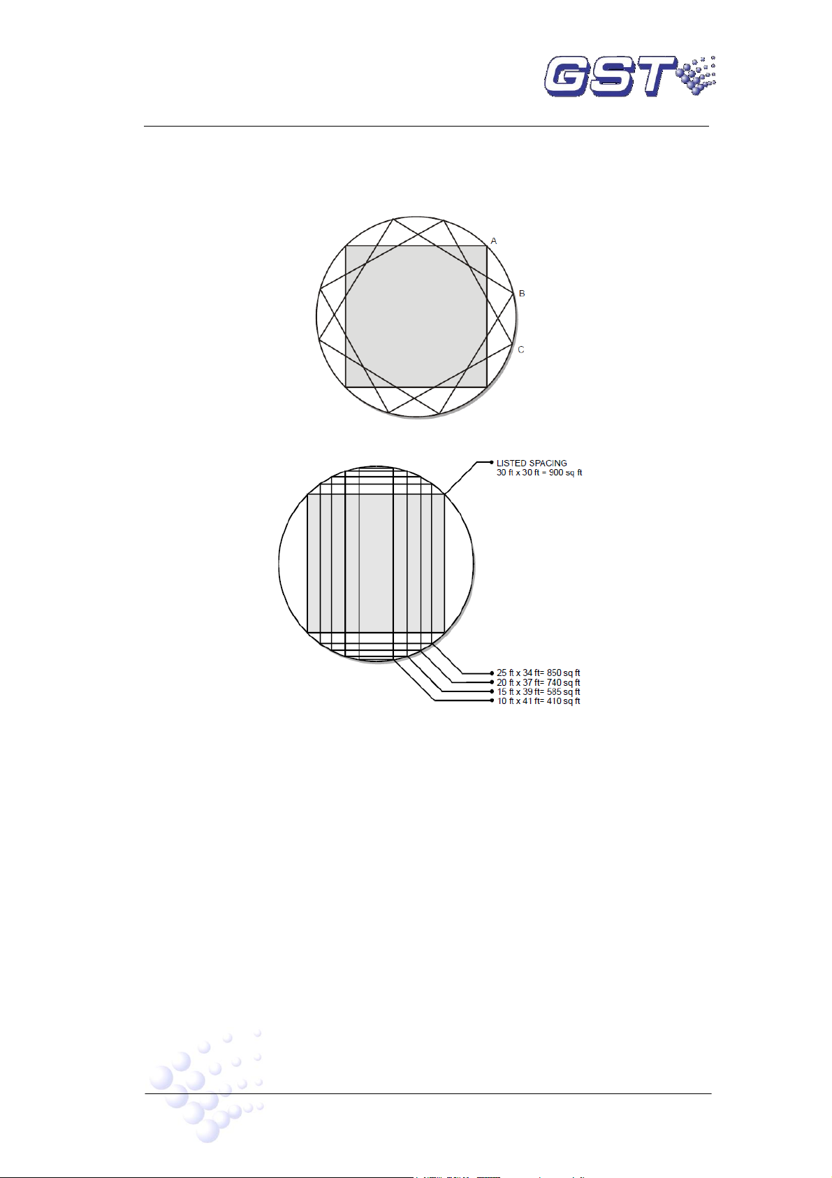
The spot type smoke detector spacing recommendation of 30 ft. (9.1 m) is based upon the
detector installation on a smooth ceiling that is 10 ft. (3 m) high. Detector coverage is
typically represented as a square, because most structures have flat sidewalls. Like spot
type heat detectors, smoke detector coverage is a circle whose radius is 0.7 times the listed
spacing. Since all of the area within the detector’s circle of coverage is suitable for detecting
smoke from fire, the shape and dimensions of the detector coverage “square” may be
modified. Note that, although the coverage “square” is a “rectangle,” the coverage area is
within the overall detector circle coverage.
Note: Unlike heat detectors, smoke detectors are not given a listed spacing. It is
recommended that smoke detectors be installed on S = 30 ft. (9.1 m) centers, on smooth
ceilings. NFPA 72 National Fire Alarm Code contains additional information regarding
spacing adjustments. When installed on the ceiling, spot type detectors must be located a
minimum of 4 in. (10cm) from sidewalls. When installed on sidewalls, the detector must be
located between 4 in. (10cm) and 12 in. (30cm) from the ceiling, unless detectors are
specifically positioned to counter the effects of ceiling construction or stratification.
3.3 Stratification
Stratified air within a room may impede smoke from reaching the detector. To improve
detection system response in situations where stratification exists, additional detectors may
be installed on sidewalls at elevations below the ceiling level as shown in the illustration.
Page 9
Page 12

Figure 11: Smoke detector spacing — solid joist construction
D = Joist depth
W = Joist spacing:
S = 30 ft. (9 m)
1/3 S = 10 ft. (3 m)
2/3 S = 20 ft. (6 m)
1/2 S = 15 ft. (5 m)
D Series Smoke and Heat Detector
Application Bulletin
3.4 Partitions
Partitions extending from the floor to within 18 in. (46 cm) of the ceiling do not influence
smoke detector spacing. Partitions closer than 18 in. (46 cm) to the ceiling may require
modification of smoke detector spacing.
3.5 Exposed solid joists
Exposed solid ceiling joists may impede the flow of smoke to detectors. When spacing spot
type smoke detectors, a joist is defined as any solid member extending 8 in. (20 cm) or more
down from the ceiling and spaced less than 3 ft.(1 m) apart. Note that this definition differs
from the one used in locating spot type heat detectors. The spacing of smoke detectors must
be reduced by 33% in the direction perpendicular to the joist. The detectors must be
mounted on the bottom of the joists.
Notes
• Joists less than 8 in. (20 cm) deep are considered flat ceilings. Smoke detectors must be
mounted on the bottom of joists.
• Spacing perpendicular to joists deeper than 8 in. (20 cm) must be reduced by 1/3 of the
listed spacing.
Page 10
Page 13

Figure 12: Smoke detector spacing — beam construction
D = Beam depth W = Beam spacing
S = 30 ft. (9 m) 1/2 S = 15 ft. (5 m)
R = Reduced spacing (see notes below)
D Series Smoke and Heat Detector
Application Bulletin
3.6 Exposed beams
Beams are defined as any members extending 8 in. (20 cm) or more down from the ceiling
and spaced more than 3 ft. (1 m) apart. Note that this definition differs from the one used in
locating spot type heat detectors. The spacing of smoke detectors must be reduced in the
direction perpendicular to the beam. Detectors may be mounted on the bottom of the beams
that are less than 12 in. (30 cm). If the beams are greater than 18 in. (46 cm) deep, each bay
created by the beams must have at least one detector mounted on the ceiling.
Smoke detectors should be mounted on the ceiling within each bay if the ratio of beam depth
(D) to ceiling height (H), D/H, is greater than 0.1, and the ratio of beam spacing (W) to ceiling
height (H), W/H, is greater than 0.4.Smoke detectors should be mounted on the bottom of
each beam if either the ratio of beam depth (D) to ceiling height (H), D/H, is less than 0.1, or
the ratio of beam spacing (W) to ceiling height (H), W/H, is less than 0.4.
Calculation:
D/H > 0.1 and W/H > 0.4 then mount the detector on the ceiling
D/H < 0.1 or W/H < 0.4 then mount the detector on the bottom of the beam
Page 11
Page 14

D Series Smoke and Heat Detector
Application Bulletin
Notes
• Detector can be located on the bottom beams if the beams are less than 12 in. (30 cm)
deep and beam spacing is less than 8 ft. (2.4 m)
• Beams less than 8 in. (20 cm) deep are considered flat ceilings. Smoke detectors must be
mounted on the bottom of the beams.
• No definite spacing reduction is specified by code for beams deeper than 8 in.(20 cm).
• If beam depth exceeds 18 in. (46 cm) and beam spacing exceeds 8.0 ft. (2.4 m) detectors
must be installed on the ceiling in each bay.
3.7 Sloped ceilings
Rooms with peaked ceilings must have the first row of detectors placed within 3ft. (1 m)
(measured horizontally) of the ceiling peak. Additional detectors, if required, must be spaced
based upon the horizontal projection of the ceiling and ceiling construction. This modification
of spacing for smoke detectors on sloped ceilings is identical to that used for spot type heat
detectors.
Rooms with shed ceilings having a slope greater than 1 ft. in 8 ft. (1 m in 8 m) must have the
first row of detectors within 3 ft. (0.9 m) of the high end of the ceiling. Additional detectors, if
required, must be spaced based upon the horizontal projection of the ceiling and ceiling
construction. For roofs having a slope less than 30 degrees, horizontal spacing must be
adjusted according to the height of the peak. For roofs having a slope greater than 30
degrees, horizontal spacing must be adjusted according to the average sloped ceiling height.
These modifications of spacing for smoke detectors on shed ceilings are identical to that
used for spot type heat detectors.
3.8 Effects of heating, ventilating, and air conditioning (HVAC) systems
When spot type smoke detectors are installed under raised floors, they are subjected to high
air velocities and dust levels. Detectors should be installed base up or base vertical (never
down) as shown in the figure below. This minimizes the effects of dirt, dust, and mechanical
interference from cabling.
Section 4 Initial installation testing
To perform an initial installation test:
1. Before testing the smoke and heat detectors, notify the proper authorities that the system
is undergoing maintenance and, unless part of the test, disconnect all auxiliary equipment.
2. Visually inspect each detector and verify it is installed in the correct location. Make sure it
will not be adversely affected by factors that are not apparent on the plans.
3. Remove the detector from its base and verify that the proper detector address, trouble
signals, and messages are reported.
4. Activate smoke detectors using an smoke aerosol spray, a smoke generator, or the Test
fire detector tester per the manufacturer’s instructions.
5. Activate rate-of-rise heat detectors using a hair dryer (maintaining a distance of three
inches).
6. After you have finished testing the smoke and heat detectors, reset the control panel in
order to restore the detectors to their normal state.
7. Notify the proper authorities that the system maintenance is complete.
Page 12
Page 15

Gulf Security Technology Co., Ltd.
No. 80, Changjiang East Road, QETDZ, Qinhuangdao, Hebei,
P. R. China 066004
Tel: +86 (0) 335 8502434
Fax: +86 (0) 335 8502532
service.gst@fs.utc.com
www.gst.com.cn
 Loading...