

Page 1
DI-M9301
Fire Alarm
Digital Single Input and Output Module
Features
Input port is provided with Class B pathway
supervision when connects with 4.7KΩ EOLR
(Part Number 3010786).
Input port c an be programmed to m onit or either
normally open or normally closed dry contact
input.
Input can also be programmed as
“self-answering”, whi ch means that the Input port
monitoring is disabled, and the module will
directly send a “status” signal to FACP w hen t he
dry-contact output changes state.
Addressable unit. Address can be programmed
in field.
Input port utilizes AD sampling technology for
precise testing.
Compatible with GST-M200 and GST-IFP4M Fire
Alarm Control Panels (FAC P).
Guide rail for easy installation.
Standard: UL864, NFPA [70, 72].
Description
Wi th a mi crop roces sor, DI-M9301 Digital Single Input
and Output Module can comm unicat e with fi re alarm
control panel (FACP). On receiving start command
from the FACP, it will close the output relay and
illuminate the Active indicator.
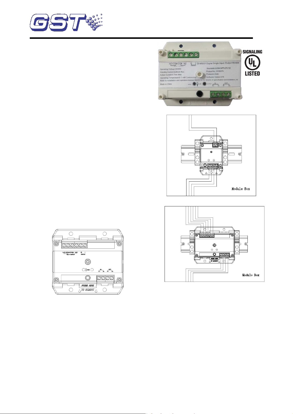
Connection and Cabling
Term inals of the module are shown i n Fig. 1.
Fig. 1
Installation
Warning:
Before installing the module, disconnect power
from the loop.
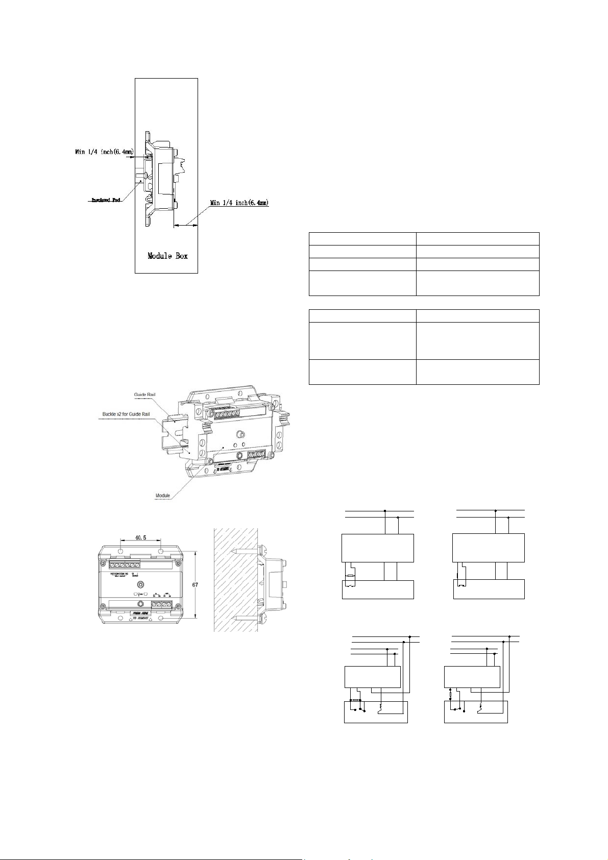
1) Befo r e i n s tal l at i on , m ak e s ur e t h e enc l o su r e is in
good condition and markings are complete.
2) The module shall either be installed in a North
Amer ic a stand ard m etal el ectr ica l bo x. Minimum
si ze is 4 i n. sq uare, 2-1/8 in depth (in thi s case,
standard box cover is required), or in a UL
Signaling Listed enclosure that provides
minimum wiring entries and sp acin g as s how n on
Fig 2 and Fig 3. Minimum mounting space is
67×40.5mm.
Fig 2
Equipment
47AU
(Z1, Z2) IN & OUT : Connecting with the Signaling
Line Circuit (SLC) loop of FACP, polarity
insensitive.
I, G: Connecting with normally open dry contact
of an input devic e that clos es when th e dev i c e i s
in al arm or ch anges s tate. It may also be set to
normally closed input by hand held programmer.
COM, NO, NC: Dry contact output terminals
.
CODE: Connecting wit h the programmer.
Reco mm ended W iri ng: m inim um 17 AWG. Su bject to
local codes.
30310199 Issue 1.06
Page 2
:
Paramet ers Setting
Input
1
Self-answering
2
normally-closed
Any other
numbers(Default)
normally-open
Paramet ers Setting
points
2
occupies two ad dresses ,
for output
numbers(Default)
and output
NC
I
Z2
Z1
COM
Z1
G
NO
Z2
I
Z2
Z1
COM
Z1
G
NO
Z2
4.7kΩ
4.7kΩ
a b
NC
Feedback
Controlled Device
Control
Input
Feedback
Control
Input
Controlled Device
DI-M9301
DI-M9301
FACP
FACP
Z2
NO
G
Z1
COM
+24V
GND
Z1
Z2
I
a
b
4.7kΩ
DI-M9301
NC
Z2
NO
G
Z1
COM
+24V
GND
Z1
Z2
I
4.7kΩ
NC
Controlled Device
Controlled Device
DI-M9301
Power
FACP
Power
FACP
Fig. 3
3) The module can be mounted on a guide rail as
shown on Fig 4.
4) The module can also be installed in the
enclosure by 4 mounting screws as shown in
Fig.5.
Application
The module connects with fire control devices which
are activated by the FACP.
The address and operating m ode of the module can
be program med b y a progr am mer in field. Please refer
to P-9910B Hand Held Programmer Installation and
Operation Manual for details.
Programming Parameters
In standby s tate of the progr am mer, press Fn and then
number 3, “—“will be popped up on the screen to
indicate it is i n pr o gr am m i ng m od e. Write a pa rameter
and then pressing “Program”, a “P” will show on the
screen mea ning th e parameter is programmed.
Press Fn and then number 3, input check ing methods
can be set.
Pressing Fn and 4 can set the number of addresses.
Any other
one for the input and one
one address for both input
30310199 Issue 1.06
Fig. 5
Fig. 4
Note: “Norm ally-clos ed” o pinio n can onl y be used for
trouble circuit, or Class E non-fire, non-emergency
input, e.g. door status sensor.
Connection of the module to field devices with
normally open dry contact is shown in Fig. 6(line
detection is provided by the controlled device).
Connection of the module to devices controlled
by 24VDC is shown in Fig.7 (line detection is
provided by the controlled equipment).
Fig. 6
Fig. 7
Page 3

Specification
Operating
Voltage
Loop 24VDC(16VDC - 28VDC)
Power Limited
Standby Current
≤ 0.28mA
Action Current
Loop ≤ 0.7mA
Output Capacity:
2A @ 30 VDC, 0.35PF.
Output Control
Way
Relay normally open/normally
closed contact input
Programming
Electronically addressing
Initiating circuit
maximum line
impedance
25Ω each wire
Address Range
Two options preset by
representing Input and Output.
programmed as input address
plus 1.
LED
Input LED: Red. It lights in
. It lights in
off in other
states.
Ingress
Protection Rating
IP30 (not tested by UL)
Operating
Temperature
0℃ - +49℃
Relativ e Humidity
≤ 93%,Non Condensing
Materials of the
Enclosure
ABS, white(RAL9016)
Dimension
((L×W×H)
85.3mm×78mm×33mm ( with
base)
Weight
About 66.5g (wit h base)
Model
Name
Remark
P-9910B
Hand Held
r
Supplied
RY-1W-4.7k±5%
End-of-Line
Resistor
Provided
This Data Sheet is subject to change without notice. Please contact GST for more information or questions.
Gulf Securi ty Technology Co., Ltd.
Accessories and Tools
manufacturer:
Opt ion 1 : Bot h Input an d Outp ut
occupy one address t hat ra nges
from 1 to 242.
Opt ion 2 : Occ u py two ad dr es s es
Input address range is 1 to 241.
Output address is automatically
receiving feedbacks, lights 0.5s
on, 0.5s off in input faults,
flashes in other states
Output LED: Red
relay action, turns
and
.
Programme
separately
Limit ed Warranty
GST warrants that the product will be free from defects
in design, materials and workmanship during the
warranty period. This warranty shall not apply to any
product that is found to have been improperly installed
or used in any way not in accordance with the
instructions supplied with the product. Anybody,
including the agents, distributors or employees, is not
in the position to amend the contents of this warranty.
Please contact your local distributor for products not
covered by this warranty.
No. 80, Changjiang East Road, QETDZ, Qinhuangdao, Hebei, P. R. China 066004
Tel: +86 (0) 335 8502434 Fax: +86 (0) 335 8502532
service.gst@fs.utc.com www.gst.com.cn
30310199 Issue 1.06
 Loading...