

Page 1

Features
Input port is provided with Class B pathway
supervisio n w hen c o nn ec ts wi t h 4.7KΩ EO L R ( Pa rt
Number 3010786).
Input port can be programmed to monitor either
normally open or normally closed dry contact input.
Electronically addressing. Addresses can be
modified in field .
Built-in microprocessor processes messages
intelligently.
Input port utilizes AD sampling technology for
precise testing.
Guide rail mounting.
Compatible with GST-M200 and GST-IFP4M Fire
Alarm Control Panels (FACP)
Standard: UL864, NFPA [70, 72.]
Description
DI-M9300 Digital Single Input Module is used for
receiving normally open or normally closed switch
signals, and transmitting the signals to fire alarm control
panel (FACP) through signaling line circuit (SL C) l oo p t o
FACP.
Connection and Cabl ing
Term inals of th e m odule are shown in F ig. 1.
Fig. 1
(Z1, Z2) IN & OUT: Connec ting with t he Signaling
Line Circuit (SLC) loop of FACP, polarity-insensitive.
I, G: Connec ting with n ormall y-open contact of an
input d evice t hat cl oses when the d evic e is in al arm or
changes state. It may also be set to normally-closed
checking input by a hand-held programmer.
COD E : Connecti ng wit h the pr ogram mer.
Recommended Wiring: minimum 17 AWG. Subject to
local codes.
Installation
Warning: Before installing the module, disconnect
power from the loop and verify that the guide rail is
securely installed.
1) Before installation, make sure the enclosure is in
good condition and markings are complete.
2) The module shall either be installed in a North
America standard metal electrical box. Minimum
size is 4 in. square, 2-1/8 in depth (in this c ase,
standard box cover is required), or in a UL
Signaling Listed enclosure that provides minimum
wiring entries and spacing as shown on Fig 2 and
Fig 3. Mini mum mounti ng space is 67 × 40.5 mm.
Fig. 2
DI-M9300
Digital Single Input Module
Fire Alarm
Equipment
47AU
30310198 Issue 1.06
Page 2
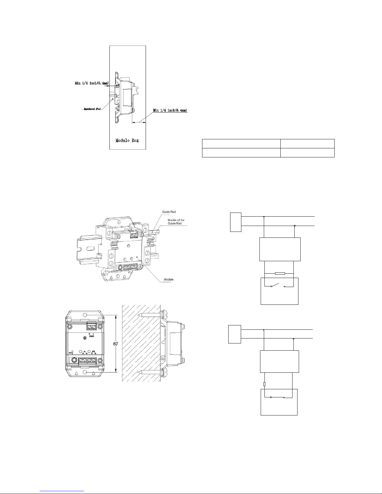
Fig. 3
3) The module can be mounted on a guide rail as
shown on Fig 4.
4) The module can also be installed in the enclosure
by 4 mounting sc rews a s shown i n Fig.5.
Fig. 4
Fig.5
Application
The module may be used to monitor status of fire
suppression devices, such as water flow indicator,
pressure switch, position switch, signal valve, and
devices that can feedback the ON/OFF signal.
Parameters can be programmed through P-9910B
programmer.
Programming Parameters:
In standby state of the programmer, press Fn and then
number “3”, “—”will be popped up on the screen to
indi cate i t is i n progr amming m ode. Write a parameter
and then press “Program”, a “P” will sh o w on t h e s cr een
meaning the parameter is programmed.
Parameters used for setting includes:
1
normally-closed
Any ot her number s(def ault)
normally-open
Note: “Normally-closed” opinion can only be used for
trouble circuit, or Clas s E non-fire, non-emergency input,
e.g. door status sensor.
Connection of the module to field devices with
normally-open dry contact is shown in Fig. 6.
Connection of the module to fi eld devices w ith
normally-closed dry contact is shown in Fig.7.
Z1 Z2
I1 G
Z1
Z2
DI-M9300
Normally Open Contact
Field Device
FACP
4.7
KΩ
End-of-line
Resistor
Fig. 6
Z1 Z2
I1 G
Z1
Z2
DI-M9300
Normally Closed Contact
Field Device
FACP
4.7
KΩ
End-of-line
Resistor
Fig. 7
30310198 Issue 1.06
Page 3

Specification
Operating Voltage Loop 24VDC
(16VDC - 28VDC)
Power Limited
Standby Current
≤ 0.26 mA
Action Current
≤ 0.5 mA
Programming
Electronically addressing
Initiating circuit
maximum line
impedance
25Ω each wire
Address Range Occupy one address from 1
to 242.
LED
Feedback LED: Red. It
lights on activation, qui et i n
loop power down, and
fl ashes i n other states.
Fault LED: Yellow. It lights
0.5s on and 0.5s off as
ther e is in put fault . It tur ns
off in other states.
Ingress Protection
Rating
IP30 ( not tested by UL)
Operating
Temperature
0℃ - +49℃
Relativ e Humidit y
≤ 93%, Non Condensing
Materials of the
Enclosure
ABS, white (RAL9016)
Dimension
((L×W×H)
78mm×45.3mm×28.5mm
(
with base)
Weight
About 36.8g (with base)
Accessories and Tools
Model
Name
Remark
P-9910B
Hand Held
Programmer
Supplied
separately
RY-1W-4.7k±5%
End of Line
Resistor
Provided
Limited Warranty
GST warrants that the product wil l b e fr ee f r om d ef ec ts i n
design, materials and workmanship during the warranty
period. This warranty shall not apply to any product that is
found to have been improperly installed or used in any
way not in accordance with the instructions supplied with
the product. Anybody, including the agents, distributors
or emplo yees, is not i n the position t o amend the contents
of t his warr anty. Pl ease contact your local distributor for
products not covered by this warranty.
This Data Sheet is subject to change without notice. Please contac t GST for more informat ion or questions.
Gulf Security Technology Co., Ltd.
No. 80, Changjiang East Road, QETDZ, Qinhuangdao, Hebei, P. R. China 066004
Tel: +86 (0) 335 8502434 Fax: +86 (0) 335 8502532
service.gst@fs.utc.com www.gst.com.cn
30310198 Issue 1.06
 Loading...