

GST DI-9104Exd Quick Start Manual
M3×16
UV Flame Detector
FACP
Z1
Z2
Z1
Z2
K1
K2
DI-9104Exd Detector
Hazardous Area
Safety Area
Input Equipment
Z1
Z2
K1
K2
DI-9104Exd Detector
24VDC
Signal
Input
Hazardous Area
Safety Area
DI-9104Exd Digital Flame Proof
Features
Built-in MCU processes signals and controls
communication digitally.
Intelligent algorithm ensures quick response to
reduced false alarms.
3 classifications available.
High sensitivity, reliable performance, and
dust-proof, damp-proof and corrosion-proof
abilities.
Description
DI-9104Exd is a light-sensitive detector that detects
fire by picking up the ultraviolet light from flaming
material. It’s designed for areas where an open fire is
li able to occ ur with la rge amou nt of radiation and no
smoldering st ag e, or w her e q u i c k r es po n s e t o a f ir e i s
required. This detector can be applicable to zone 1
and 2 of explosive hazardous areas.
The detector is able to work either in addressable
mode connecting with GST intelligent fire alarm
control panel(FACP) to transmit signal through
detecti on loop or in non-addressable mode connecting
to 24VDC power supply to transmit signal by
outputting di f ferent resistan ce values.
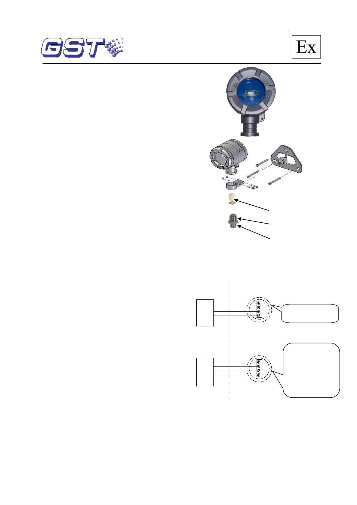
M6×60
Sealing and washer,
φ8mm(inter nal di ameter )
M24×1.5
Connection and Wiring
Screened 2-core cable with cross section 1mm2 or
abo ve, an d outer diameter φ8 mm is required for field
wir ing. Please foll ow the steps bel ow:
(1) Rotate down the back cover and the pressing nut.
(2) Thread a proper length of the cable through the
pressing nut, metal washer and joint washer in
sequence.
(3) Peal away the outer layer of the cable with 5mm of
metal core exposed, rotate in the cable together
with the joint washer, metal washer and the nut into
the detector housing, and fasten the nut using a
spanner.
(4) Connect the cables to corresponding terminals of
the detector, and the screen layer to the safety
earth position inside the housing.
(5) Fast en the back cover with tools, and make sur e
the detector is earthed through its safety earth
position on the cover.
Installation
(1) Fig. 1 is the schematic diagram for installing the
detector.
(2) Pl ease check the following after installation:
There shall not be any crack or air bubbles.
The back cover and the detector shall be
securely fastened.
There shall not be any scratch or crack on the
detecting window.
There shall be joint washer in the wiring hole.
The joint washer matches with the cable
diameter.
The pressing nut is locked.
There is earth cab le at th e “ earth” mark .
The det ecti on win dow shal l face t he pro tected
area.
Note: The d etector shall be in stalled in compliance
with relative installation codes. Make sure the
housing is in good condition.
30309304 Issue 1.06
NPT 1/2
Fig. 1
Application
Schematic of system connection is shown in Fig. 2
(addressable mode) and Fig .3 (non-addressable mode).
Z1and Z2 connects w ith the loop
of FACP, polarity-ins ensitive.
Fig. 2
Z1, Z2: Pow er inpu t ,
polarity-insensitiv e.
K1, K2: Signal output.
Resistance between the
terminals is 4.7kΩ norma lly.
Shorted in fire alarm
condition.
Open in fault condition.
Fig. 3
Operation
The detector powered by 24VDC voltage, which may
come from control panel in addressable working mode
or 24VDC power suppl y in non-addressable working
mode.
In addressable mode, Terminal Z1 and Z2 are to be
connected with the loop of FACP polarity-insensitively.
The FACP p olls the detector status through the loop,
and displays its fau l t and fire alarm mes sages.
Operating Voltage
Addressable Mode:
fr om FACP Z1,Z2 terminals
Non-addressable Mode:
power supply
Operating Current
Addressable Mode:
Alarm current ≤ 3mA
Non-addressable Mode:
Alarm current ≤ 23mA
Power-up Time
≤10s
Indicator
In addressable mode and
illuminates steadily in alarm.
Programming Mode
Electronic programming.
Occupying one loop
address.
Address Range
1~242
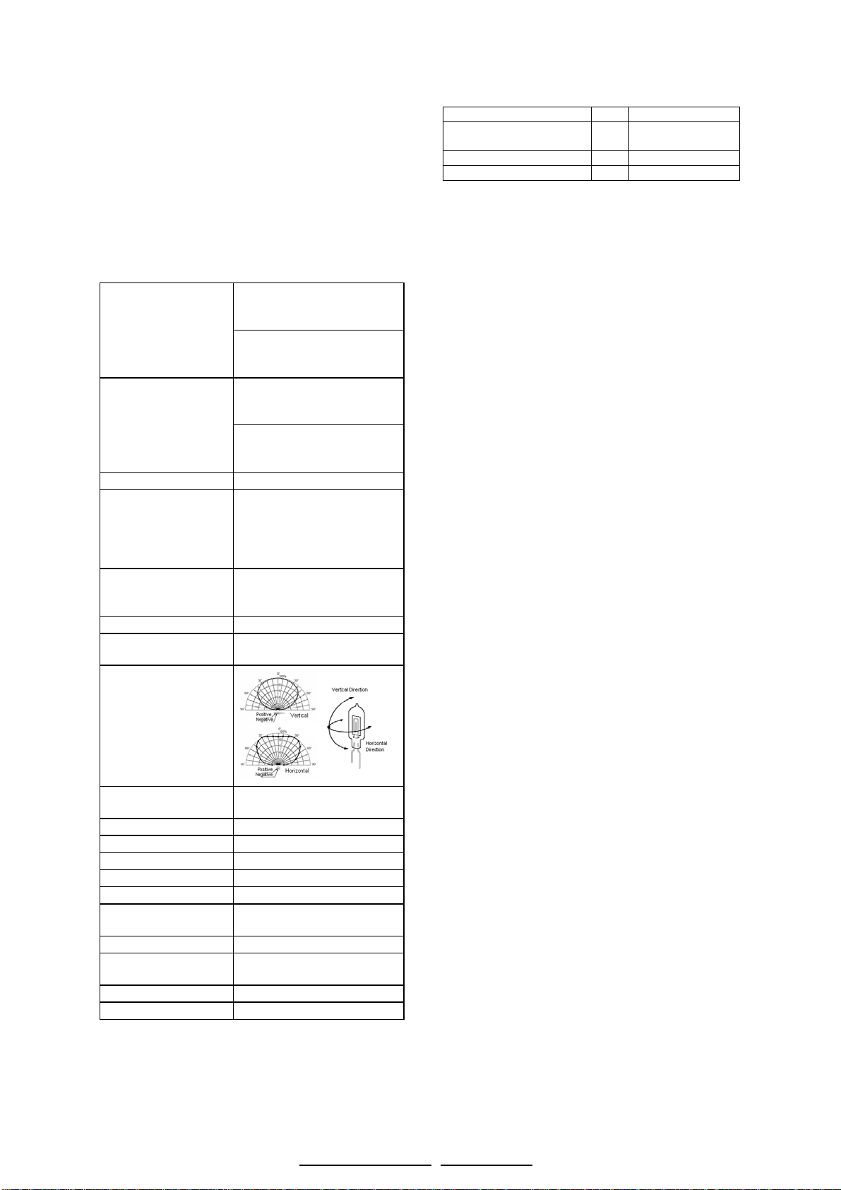
Spec trum R esponse
Range
185nm~260nm
Detection Angle
Detection
Distance※
25m for Class 1, 17m for
Class 2 and 12m for Class 3.
Alarm Respon se time
≤30s
Ingress P rotection
IP66
Ambient Temperatur e
-20 ℃~+60 ℃
Relativ e Humidity
≤95%RH, non-condensing
Dimensions
147mm×106mm×92mm
Mat erial and Color
ZL102 alumi num alloy,
silvery grey.
Weight
1.5kg
Installation Hole
Spacing
110mm×72mm
ATEX Cert i ficate NO.
Presafe 14 ATEX 5547
Explosion-proof Mark
Ex dⅡCT6Gb
Nam e and Mod el
Qty.
Remarks
P-9910B Hand Held
Programmer
1
Ord er separa tely
Expansion Bolt M6×60
3 Screws M3×16
2
Gulf Security Technology Co., Ltd.
In non-addressable mode, 24VDC power supply can
be directly applied to Terminal Z1 and Z2. K1 and K2
output different resistance in different conditions. I f the
resistance is 4.7kΩ, t he det ector is in no rmal s tandb y
state; if the terminals are shorted, the detector is in fire
condition; if the terminals are open, the detector is in
fault condition.
The d etec to r h as 3 classifications. The factory default
is Class 1. The addr ess and sensiti vity can be read
and changed using P-9910B Programmer. Please
refer to P-9910B Hand Held Programmer Operation
Manual for details.
Specification
Loop voltage: 24VDC come
Voltage: 24VDC come from
Standby current ≤ 2mA
Standby current ≤ 13mA
non-addressable mode,
indic ator is red. It flashes
when polling, and
Accessories and Tools
Maintenance
(1) The detector shall be cleaned at least once a year
to ensure normal operation of the system.
(2) Before cleaning, notify the proper authorities that
the system is undergoing maintenance and will
temporarily be out of service. Disable the zone or
system undergoing maintenance to avoid
unwanted alarms.
(3) The detector shall be tested after being cleaned
and re-installed. After testing, notify the proper
authorities the system is back in operation.
Caution
(1) The detector should be handled with care during
storage, transportation, installation, commission
and maintenance to avoid damage from falling,
im pact, ou t side f orce an d f riction.
(2) Instal lation and maintenance should strictly comply
with relative codes for explosive and hazardous
areas.
(3) Never open the cover for maintenance in field.
(4) The enclosure must be earthed.
(5) The len only endures low impact energy, so the
detector shall be installed the position wher e the
foreign objects can’t attack it.
(6) The following places are not suitable for the
detector:
Where flameless fire is to be exp ected.
Where intensive smok e spread s before flames.
Where the "view" of the det ector is opt to be
obscured.
Where the sun can directly shine or i ndir ectly
shine the d etecti on window.
Wher e ther e is st rong UV lig ht so urce in fiel d,
like a tungsten halogen lamp.
Where open fire, welding, X rays, arc or sparks
may exist in normal condition.
(7) The threaded entries comply with following
parameters:
Position on the equ ipment: see Fig.1
The number permitted:1
Sealing and washer size: φ8mm(internal
diameter) × φ18mm(external diameter) ×
20mm(thickness)
Cable external diameter φ6~φ8 mm is
recommended
The torque for cable nut is 25 N .m t o c om pr es s
sealing ring
※Test fi re: Th e flam e generat ed by 200 0g of alc ohol
(concentration above 90% ) in a c ont ai n er wi th b ot tom
area 33cm×33cm and height 5cm.
This Data Sheet is subject to change without notice. Please contac t GST for more infor mation or que stions.
30309304 Issue 1.06
Limit ed Warranty
GST warrants that the product will be free from defects
in design, materials and workmanship during the
warranty period. This warranty shall not apply to any
product that is found to have been improperly installed
or used in any way not in accordance with the
instructions supplied with the product. Anybody,
including the agents, distributors or employees, is not
in the position to amend the contents of this warranty.
Please contact your local distributor for products not
covered by this w ar ranty.
No. 80, Changjiang East Road, QETDZ, Qinhuangdao, Hebei, P. R. China 066004
Tel: +86 (0) 335 8502434 Fax: +86 (0) 335 8502532
service.gst@fs.utc.com www.gst.com.cn
 Loading...