

Page 1
Table
Description
Strobe, white
Strobe, red
110
75
30
15
J2
J3
J1
(1)
(1) (2)
DC-M9415 Series Wall Mount
Strobe Installation Sheet
Description
The DC-M9415 Series Wall Mount Strobe is a visible fire alarm
notification appliance that is designed for mounting on indoor walls.
See Table 1 for a list of model numbers.
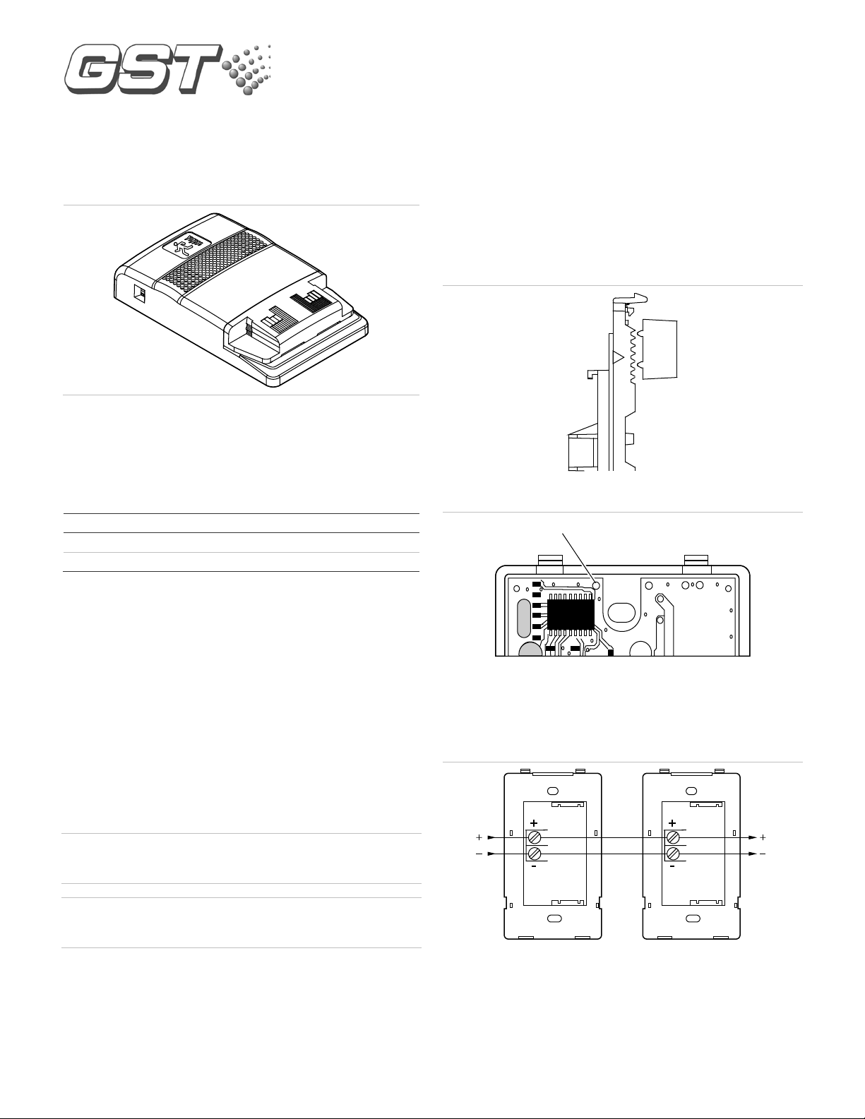
2. Slide the candela switch to the desired candela output (15, 30, 75,
or 110 cd) by aligning it with the indicator located beside the
switch. See Figure 1.
3. Set the strobe signal if required. See Figure 2.
4. Connect the strobe terminals to the signal circuit field wiring. You
must observe polarity for the unit to function properly. See
Figure 3.
5. Mount the unit onto a compatible electrical box, making sure not to
over-tighten the mounting screws.
6. Replace the cover by aligning at the bottom, then snapping in at
the top.
7. Test the unit for proper operation.
Figure 1: Candela switch
1: Models
Model number
DC-M9415W
DC-M9415R
The strobe includes a field-configurable switch for selecting the desired
candela output and a field-configurable jumper for the strobe signal
output. The candela output setting is locked in place and remains
visible after final installation.
This strobe features an enhanced synchronization circuit to comply
with the latest requirements of UL 1971 Signaling Devices for the
Hearing Impaired.
Synchronized operation requires that you connect the DC-M9415
Series Wall Mount Strobe to a NAC output set for Synch Mode, or to a
separate DC-M9410 Signal Synchronization Module.
Installation
Install and wire this device in accordance with applicable national and
local codes, ordinances, and regulations.
WARNING: Electrocution hazard. To avoid personal injury or death
from electrocution, remove all sources of power and allow 10 minutes
for stored energy to discharge before installing or removing equipment.
Caution: Electrical supervision requires breaking the wire run at each
terminal. Do not loop the signaling circuit field wires around the
terminals.
To install the strobe:
1. Remove the cover by depressing both tabs on the top of the unit
with a small screwdriver and twisting slightly.
Figure 2: Strobe signal setting
(1) To change the strobe to temporal (private mode), cut from circle J1
to the edge of circuit board.
Note: If the strobe is set to temporal (private mode), this device is no
longer UL 1971 listed, but is UL 1638 listed.
Figure 3: Wiring diagram
(1) From NAC output
(2) To next appliance, EOLR, or return to source
Note: Polarity is shown in the alarm condition.
© 2017 United Technologies Corporation 1 / 2 P/N 30310840-EN • REV 001 • ISS 27MAR17
Page 2
Maintenance
Operating
Strobe operating
Light output
Synchronization
Strobe signal rate
Wire size
Compatible electrical
boxes
Operating environment
Table
16 Vdc
16 Vfwr
VDC
VFWR = Volts full wave rectified
100
9590858075706560555045403530252015
10
505
1015202530354045505560657075808590
95
100
0
5
10
15
20
25
30
35
40
45
50
55
60
65
70
75
80
85
90
-5
-10
-15
-20
-25
-30
-35
-40
-45
-50
-55
-60
-65
-70
-75
-80
-85
-90
Angle
Percentage of rated output
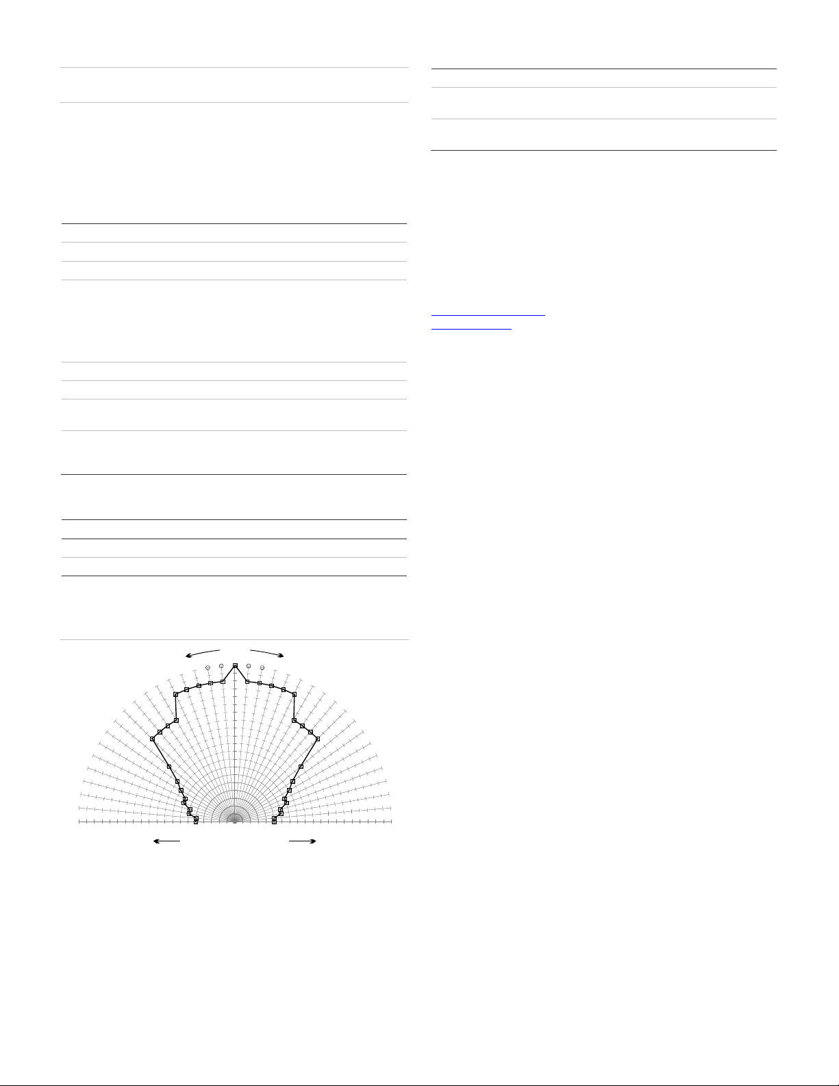
Horizontal and vertical outputs reflect the same pattern.
UL
Environmental
class
North American
standards
Caution: To maintain the required agency listings, do not change
factory applied finishes.
This unit is not serviceable or repairable. Should the unit fail to
operate, contact the supplier for replacement.
Perform a visual inspection and an operational test twice a year or as
directed by the local authority having jurisdiction.
Specifications
voltage 24 VDC or 24 VFWR nominal
current See Table 2
Selectable at 15, 30, 75, and 110 cd
Meets UL 1971 requirements. Maximum
1 flash per second (fps)
12 to 18 AWG (0.75 to 2.50 mm²)
Temperature
Relative humidity
allowed resistance between any two devices
is 20 Ω. Refer to specifications for the
synchronization control module, this strobe,
and the control panel to determine allowed
wire resistance.
Single-gang box, 2-1/2 in. (64 mm) deep
32 to 120°F (0 to 49°C)
0 to 93% noncondensing
Regulatory information
rating Regulated 24 VDC and 24 VFWR
UL: Indoor, Dry
UL 1638 and UL 1971
Contact information
For information or questions, please contact:
Gulf Security Technology Co., Ltd.
No. 80, Changjiang East Road,
QETDZ, Qinhuangdao, Hebei, P. R. China 066004
Tel +86 (0) 335 8502434
Fax +86 (0) 335 8502532
service.gst@fs.utc.com
www.gst.com.cn
2: Strobe operating current in RMS (A)
0.103 0.141 0.255 0.311
0.125 0.179 0.346 0.392
= Volts direct current, regulated and filtered
Figure 4: UL 1971 minimum light output (% of rating vs. angle)
2 / 2 P/N 30310840-EN • REV 001 • ISS 27MAR17
15 cd 30 cd 75 cd 110 cd
 Loading...