

Page 1
30309460 Issue 1.06
Features
Providing for connections to remote indicators.
A magnet test available.
Standard: UL268
Description
DC-M9102 Conventional Photoelectric Smoke Detector (the
detector) is a new-generation product by building in a
microprocessor, embedding a solid fire analyzing program, and
performing effectively and efficiently.
Checking a fire alarm signal, the detector will send it to a fire alarm
control panel (FACP) or addressable zone monitor unit by means of
current changes. The detector indicates its fire condition by turning
on fire LED and keeping the LED on until it is reset.
Using infrared scattering technology, with an innovative chamber,
the detector receives very weak infrared light under normal
smokeless condition. If smoke particles enter the chamber, the
received light signal will increase by scattering. When smoke
density reaches certain density, the detector will output fire signal. In
order to reduce interference and power consumption, the emitting
circuit works in pulse mode to prolong the life of IR LED.
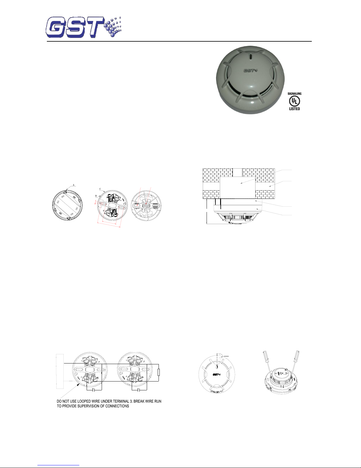
Connection and cabling
The detector connects with our UL certified GST-M200 FACP and
I-M9300 Module. DB-M01 base shown in Fig. 2 is used together.
5
45
75
Cable Entry
Mounting
Hole
Fig. 1 Fig. 2
Please install the base according to the following steps:
1) Locate the mounting holes on the rubber seal of the base
according to the holes on the electrical junction box, and
punch the holes with a screwdriver.
2) Count the number of cables needed and punch correct
number of holes with a screwdriver on the rubber seal at the
cable entry position. Thread the cables through the cable
entry holes.
3) Install the base onto the junction box with screws.
Warning: Do not punch mounting holes and cable entry holes
bigger than needed. Do not punch more holes than needed.
There are four terminals with number on the base. “1” is connected
with output anode of I-M9300 module; “2” is used as output,
connected with anode of next detector (Terminal 1) and also
connected with anode of remote indicator; “3” is connected with
output cathode of I-M9300 module or the cathode of the power supply;
“4” connects with the cathode of remote indicator. Connect 4.7k/1w
resistor to terminal 2 and 3 of the base. Maximum 15 detectors can
be connected to the output circuit of I-M9300 The system connection
is shown in Fig. 3.
Remote Indicator
O-
O+
I-M9300
Conventional Detector
4.7kΩ Resistor
Remote Indicator
Conventional Detector
Fig. 3
Recommended Wiring
1.0mm2 or above fire cable for all terminals laid through metal conduit
or flame proof conduit, subject to local codes.
Note: Different color cables are used to avoid wiring mistake.
Installation
Refer to D Series Detector Application Bulletin for additional installation
instructions.
Fix the base with two taping screws. Then align A (Fig.1) on the
bottom of the detector to B (Fig.2) of the base, and rotate the
detector clockwise to mark C.
Mounting of the detector is shown in Fig.4.
Electrical Box
Conduit
Orientation Base
Detector
54.5mm
Fig. 4
Application
Notes: The alarm current depends on the current limit of the
control panel. 24VDC cannot power the detector directly.
Otherwise the detector will be blown up for lack of current limit
resistor.
Testing
Before testing, please ensure that the detector has been
installed correctly and powered up. After 10 seconds, testing
can begin.
Before testing, notify the proper authorities that the system is
undergoing maintenance and will temporarily be out of service.
Disable the zone or system undergoing maintenance to avoid
unwanted alarms.
All detectors must be tested after installation and periodically
thereafter. Testing methods must satisfy the Authority Having
Jurisdiction (AHJ). Detectors offer maximum performance when
tested and maintained in compliance with NFPA 72. The detector
can be tested in the following way:
Test zone
Fig. 5 Fig. 6
1) Magnetic test
Magnet test zone is shown in Fig.5. Put the magnet of commission
tool close to the zone of the detector and hold on for a few seconds
until the detector generates alarm.
2) Smoke test
The Trutest model 300 Aerosol Smoke Detector Tester can be used
DC-M9102
Conventional Photoelectric
Smoke Detector
Page 2
30309460 Issue 1.06
for smoke entry testing. Set the generator to represent 4%/ft to 5%/ft
obscuration as described in the Trutest manual. Using the bowl
shaped applicator, apply aerosol until the panel alarms.
Additionally, canned aerosol simulated smoke (canned smoke agent)
may be used for smoke entry testing of the smoke detector.
Recommended aerosol smoke products are:
Manufacturer
Model
Trutest
AERO400
When used properly, the canned smoke agent will cause the smoke
detector to go into alarm. Refer to the manufacturer’s published
instructions for proper use of the canned smoke agent.
3) After testing, cut off the power above 10 seconds and reset the
detector and then notify the proper authorities that the system is
back in operation.
Warning: Canned aerosol simulated smoke (canned smoke agent)
formulas will vary by manufacturer. Misuse or overuse of these
products may have long term adverse effects on the smoke detector.
Consult the canned smoke agent manufacturer’s published
instructions for any further warnings or caution statements.
When testing is complete, restore the system to normal operation
and notify the proper authorities that the system is back in operation.
Maintenance
1. The detector must be cleaned once a year to ensure normal
operation of the system.
2. Before cleaning, notify the proper authorities that the system is
undergoing maintenance and will temporarily be out of service.
Disable the zone or system undergoing maintenance to avoid
unwanted alarms.
Chamber Clearing Steps:
a) Open the top cover of detector, and draw out the sensing
chamber by slightly lifting its two sides using a straight
screwdriver, as shown in Fig. 6.
b) Use a vacuum cleaner or cleaned, compressed air to
remove dust and debris from the insect guard and the sensing
chamber. The sensing chamber can also be cleaned by clear
water and brush. Put the sensing chamber in clean water to
brush the dust inside and take out to dry it.
c) Install the sensing chamber and the top cover back.
Cautions
1. Dust covers can’t be removed until the project is put into use
formally. Take well care of dust covers for future use.
2. Dust covers effectively but not absolutely prevent dust particles
from going into detectors. So, we recommend that detectors
should be removed prior to construction, decoration, or other
activities producing dust. The proper authority should be informed
of detectors removing.
3. Be careful not to damage the detector in maintenance.
4. The smoke detector may not sense fire that where smoke
cannot reach it, such as in chimneys, in walls, on roofs, or on the
other side of closed doors.
5. The detector cannot monitor the place beyond protection area.
6. The detector may not warn you about fires caused by
insufficient safety measures, violent explosions, leaking gas,
improper storage of flammable materials like diluents and other
safety hazards, arson or children playing with fire.
7. The alarm of a smoke detector used in high velocity
environment will be delayed due to dilution of smoke by frequent
and fast airflow.
8. Smoke detectors have their own service life. In order to keep
the detector working in good condition, please maintain them
according to recommendations from manufacturers and relative
state standards.
9. The detectors must be tested regularly, at least once a year.
10. Smoke detectors are not to be used with detector guards
unless the combination has been evaluated and found suitable for
that purpose.
Specification
Operating Voltage
16VDC~28VDC
Standby Current
≤60μA
Alarm Current
≤55mA
Fire LED
Red, flash in polling and illuminate in
alarming.
Remote indication
output
Polarity-sensitive output, directly connecting
with remote indicator (built in 10k resistor in
series, max. output current is 2mA); don’t
illuminate when in normal; flash in alarming.
Max. ripple
voltage
2V(peak to peak value)
Alarm reset
Instant power down (10s Min, 1.0VDC Max
Wiring
Two-wire, polarity sensitive.
Sensitivity Range
1.23%~3.20% per ft
Environment
Temperature
32℉(0℃)~100℉(+37.8℃)
Relative Humidity
≤95%, non condensing
Material and color
ABS, white (RAL 9016)
Ingress Protection
Rating
IP2X
Dimension
Diameter:100mm Height: 44.5mm (without
base)
Mounting Hole
Spacing
45mm-75mm
Weight
About 110g
Accessories and Tools
Model
Name
Remark
P-9910B
Hand held programmer
Supplied separately
DB-M01
Base
Supplied separately
T-MT
Commission tool
Supplied separately
C-9314P
Remote Indicator
Supplied separately
BP-9314P
Base Plate for Remote
Indicator
Supplied separately
Limited Warranty
GST warrants that the product will be free from defects in design,
materials and workmanship during the warranty period. This
warranty shall not apply to any product that is found to have been
improperly installed or used in any way not in accordance with the
instructions supplied with the product. Anybody, including the
agents, distributors or employees, is not in the position to amend the
contents of this warranty. Please contact your local distributor for
products not covered by this warranty.
This Data Sheet is subject to change without notice. Please contact GST for more information or questions.
Gulf Security Technology Co., Ltd.
No. 80, Changjiang East Road, QETDZ, Qinhuangdao, Hebei, P. R. China 066004
Tel: +86 (0) 335 8502434 Fax: +86 (0) 335 8502532
service.gst@fs.utc.com www.gst.com.cn
 Loading...