

Page 1
30309581 Issue 1.08
Features
Reed switch testing.
Remote indicator output available.
2 levels smoke sensitivities programmable, complies with
UL268. Heat part is fixed temperature, complies with UL521.
Description
DC-M9101 Conventional Combination Heat Photoelectric Smoke
Detector integrates photoelectric detection and fixed temperature
detection technology by combining smoke sensor and
semi-conductor heat sensor in mechanism and circuitry structure.
Just because of the combination of smoke detection and heat
detection, it not only overcomes the disadvantage that detectors
using common infrared scattering technology are insensitive to
black smoke with small particles, but also can pick up fire with
obvious rise of temperature such as alcohol flame, thus extending
its application range.
On detecting a fire signal, it can change its own current to transmit
the signal to fire alarm control panel (FACP) or addressable zone
monitor unit. The detector keeps illuminating fire LED until it is reset
by power-down.
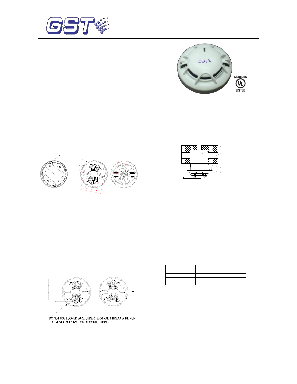
Connection and Cabling
The detector connects with UL-certified products such as I-M9300
module and intelligent control panels. The detector bottom is shown
in Fig. 1 and the base in Fig. 2.
5
45
75
Cable Entry
Mounting
Hole
Fig. 1 Fig. 2
Please install the base according to following steps:
1) Locate mounting holes on the rubber layer of the base
according to the holes on the back box, and punch the holes
with a screwdriver.
2) Count the number of cables needed and punch correct
quantity of holes with a screwdriver on the rubber layer.
Thread the cables through the cable entry holes.
3) Install the base onto the back box with screws.
Warning: Do not punch mounting holes and cable entry holes
bigger than needed. Do not punch more holes than needed.
There are four terminals with numbers on the base.
1: Detection zone positive IN
2: Detection zone positive OUT
3: Detection zone negative IN and OUT
2: Positive terminal of remote indicator
4: Negative terminal of remote indicator
It connects a 4.7k/1w resistor between number 2 and 3 at the end
of the base. The system connection is shown in Fig. 3.
Remote Indicator
O-
O+
I-M9300
Conventional Detector
4.7kΩ Resistor
Remote Indicator
Conventional Detector
Fig. 3
Recommended Cabling
1.0mm2 or above fire cable is recommended, laid through metal or
flame-retardant conduit, but subject to local codes. Different color
cables for remote indicator are used to avoid wiring mistake.
I-M9300 modules connect with 15 conventional devices at most.
Note: It’s recommended to use cables of different colors to
avoid incorrect wiring.
Installation
Refer to D Series Detector Application Bulletin for additional
installation instructions.
A fixed installation direction is ensured by the location elements on
the detector and the base. Fix the base with two tapping screws,
and then align mark A on the detector with B on the base, rotate the
detector to align mark A with mark C (Refer to Fig. 1 and 2 for the
position of the marks), the detector will be fitted to the base.
Fig. 4 shows the installation of the detector.
54.5mm
Electrical Box
Conduit
Base
Detector
Fig. 4
Application
Warning: The alarm current depends on the current
limit of the control panel. 24VDC cannot power the
detector directly. Otherwise the detector will be
blown up for lack of current limit resistor.
Fixed temperature and level 2 are default. Sensitivity level of the
detector can be set, read or written in field by using P-9910B
programmer.
In power-on state, input unlocking password and press Clear to
unlock. Press Function, then press “3”, the screen shows “_” at the
last digit.
Input corresponding sensitivity or parameter and press Program, the
screen will show a “P”, the corresponding sensitivity or parameter is
programmed. Press Clear to clear the "P". Input locking password
and press Clear to return.
Parameters set using programmer
Input Parameter
of a Detector
Smoke
Sensitivity
Heat Part
1
1
Fixed
2
2
Fixed
Read Sensitivity Level: in power-on state, pressing Test, the screen
displays address of the detector. Pressing “Up”, display sensitivity
level, device type and initial sensitivity in turns.
Testing
Before testing, please ensure that the detector has been
installed correctly and powered up. After 10 seconds, testing
begins.
Before testing, notify the proper authorities that the system is under
maintenance and will temporarily be out of service. Disable the
automatic controls relating to the zone or system under
maintenance to avoid unwanted actions.
All detectors must be tested after installation and periodically
thereafter. Testing methods must satisfy the Authority Having
Jurisdiction (AHJ). Detectors offer maximum performance when
tested and maintained in compliance with NFPA 72. The detector
can be tested in the following way:
DC-M9101 Conventional Combination
Heat Photoelectric Smoke Detector
Page 2
30309581 Issue 1.08
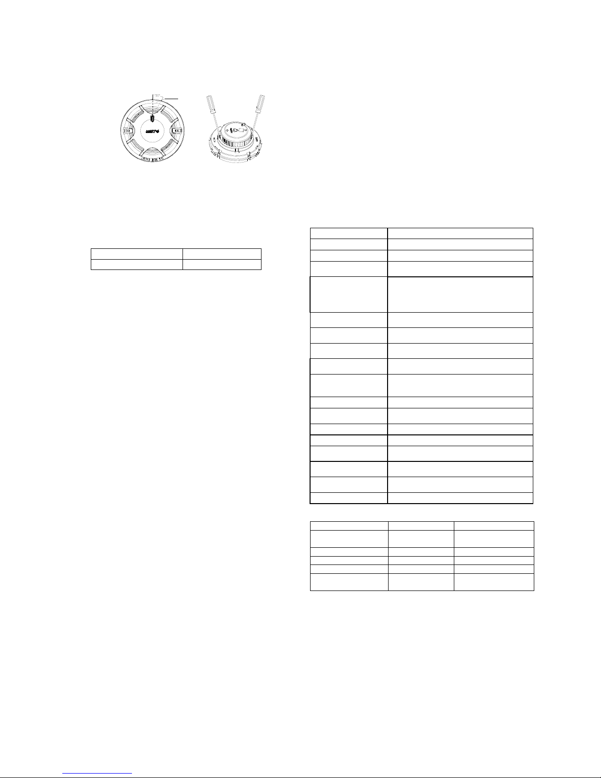
1) Reed Switch Testing
Magnetic test zone is shown in Fig. 5. Put the magnet of
commission tool close to that of the detector and hold on for a few
seconds until the detector generates alarm.
Test Zone
Fig. 5 Fig. 6
2) Smoke entry test
The Trutest model 300 Aerosol Smoke Detector Tester can be
used for smoke entry testing. Set the generator to represent 4%/ft
to 5%/ft obscuration as described in the Trutest manual. Using the
bowl shaped applicator, apply aerosol until the panel alarms.
Additionally, canned aerosol simulated smoke (canned smoke
agent) may be used for smoke entry testing of the smoke detector.
Recommended aerosol smoke products are:
Manufacturer
Model
Trutest
AERO400
When used properly, the canned smoke agent will cause the
smoke detector to go into alarm. Refer to the manufacturer’s
published instructions for proper use of the canned smoke agent.
Warning: Canned aerosol simulated smoke (canned smoke
agent) formulas will vary by manufacturer. Misuse or overuse of
these products may have long term adverse effects on the
smoke detector. Consult the canned smoke agent
manufacturer’s published i nstructions for any further warnings or
caution statements.
3) Temperature rise test
Approach a heater (such as a hair drier of 1000w-1500w) to the
thermistor of the detector until it alarms. It is 12 inches between the
hair drier and the thermistor to avoid damaging on the plastic
enclosure of the detector
If a detector fails in testing, replace it. After testing, reset the
detector. Notify the proper authorities that the system is back to
normal operation.
Maintenance
Clean the detectors regularly, at least once a year to ensure
normal operation of the system.
If unwanted alarms are often found of the detector on site, the
sensing chamber should be cleaned. Power must be removed
from the detector before cleaning.
Steps for chamber cleaning:
a) Open the top cover of detector, and draw out the sensing
chamber by slightly lifting its two sides using a straight
screwdriver, as shown in Fig. 6.
b) U Use a vacuum cleaner or cleaned, compressed air to
remove dust and debris from the insect guard and the
sensing chamber. The sensing chamber can also be
cleaned by clear water and brush. Put the sensing
chamber in clean water to brush the dust inside and take
out to dry it.
c) Put back the chamber and the top cover.
Cautions
1. Dust covers can’t be removed until the project is put into use
formally. Take well care of dust covers for future use.
2. Dust covers effectively but not absolutely prevent dust particles
from going into detectors. So, we recommend that detectors
should be removed prior to construction, decoration, or other
activities producing dust. The proper authority should be informed
of detectors removing.
3. Be careful not to damage the detector in maintenance.
4. The smoke detector may not sense fire that where smoke
cannot reach it, such as in chimneys, in walls, on roofs, or on the
other side of closed doors.
5. The detector cannot monitor the place beyond protection area.
6. The detector may not warn you about fires caused by
insufficient safety measures, violent explosions, leaking gas,
improper storage of flammable materials like diluents and other
safety hazards, arson or children playing with fire.
7. The alarm of a smoke detector used in high velocity
environment will be delayed due to dilution of smoke by frequent
and fast airflow.
8. The smoke detector cannot last forever. In order to keep the
detector working in good condition, please maintain the equipment
continuously according to recommendations from manufacturers
and relative state standards.
9. The detectors must be tested regularly, at least once a year.
10. The base should be fastened and the wire should be connected
reliably.
11. Fire LED of the detector should face the main entrance where
people can watch it easily.
12. Smoke detectors are not to be used with detector guards
unless the combination has been evaluated and found suitable for
that purpose.
Specification
Operating Voltage
24VDC(16VDC~28VDC)
Standby Current
≤60μA
Alarm Current
≤55mA
Fire LED
Red. Flashes in polling, and illuminates in
alarm
Remote Indicator
Output
Polarized output. Directly connect to remote
indicator (built in 10k resistor in series,
output current is 2mA); Flash in alarming
and do not illuminate in normal.
Maximum Ripple
Voltage
2V ( peak-to-peak)
Alarm Reset
Instantaneous cut-out (10s Min,
1.0VDCMax.)
Wiring
Non-polarized 2-core for loop.
Polarized 2-core for remote indicator.
Setting of sensitivity
and range
Level 1: 1.23%~2.7% per ft
Level 2: 2.0%~3.89% per ft
Maximum spacing
(When Used as a
Heat Detector only)
50 ft. (15.2 m)
Action Temperature
135℉(57.2℃)
Environment
Temperature
32℉(0℃)~100℉(+37.8℃)
Relative Humidity
≤95%, non condensing
Material of Enclosure
ABS White (RAL 9016)
Ingress Protection
Rating
IP2X
Dimensions
Diameter: 100mm
Height: 54.5mm (with base)
Mounting Hole
Distance
45mm-75mm
Weight
110g
Accessories and Tools
Model
Name
Remark
P-9910B
Hand held
programmer
Order separately
DB-M01
Base
Order separately
T-MT
Commission Tool
Order separately
C-9314P
Remote Indicator
Order separately
BP-9314P
Back Plate for
Remote Indicator
Order separately
Limited Warranty
GST warrants that the product will be free of charge for repairing or
replacing from defects in design, materials and workmanship during
the warranty period. This warranty does not cover any product that is
found to have been improperly installed or used in any way not in
accordance with the instructions supplied with the product. Anybody,
including the agents, distributors or employees, is not in the position
to amend the contents of this warranty. Please contact your local
distributor for products not covered by this warranty.
This document is subject to change without notice. Please contact GST for more information or questions.
Gulf Security Technology Co., Ltd.
No. 80, Changjiang East Road, QETDZ, Qinhuangdao, Hebei, P. R. China 066004
Tel: +86 (0) 335 8502434 Fax: +86 (0) 335 8502532 service.gst@fs.utc.com www.gst.com.cn
 Loading...