

Page 1
30309767 Issue 1.04
Features
High bright red LEDs are used as light source.
Sound level: 85dB (A weighted, 3m in front).
Description
DC-9404(IS) Intrinsically Safe Conventional Sounder
and DC-9403(IS) Intrinsically Safe Conventional
Sounder Strobe (hereinafter called the
sounder/sounder strobe) is a kind of audible/audible
and visual alarm device used to warn people in field
when fire occurs. It’s applicable to zone 1 and zone 2
of areas with explosion-proof requirement in
petroleum and chemical industries. It can match with
I-9333 Interface.
Base with 25.5mm high are available.
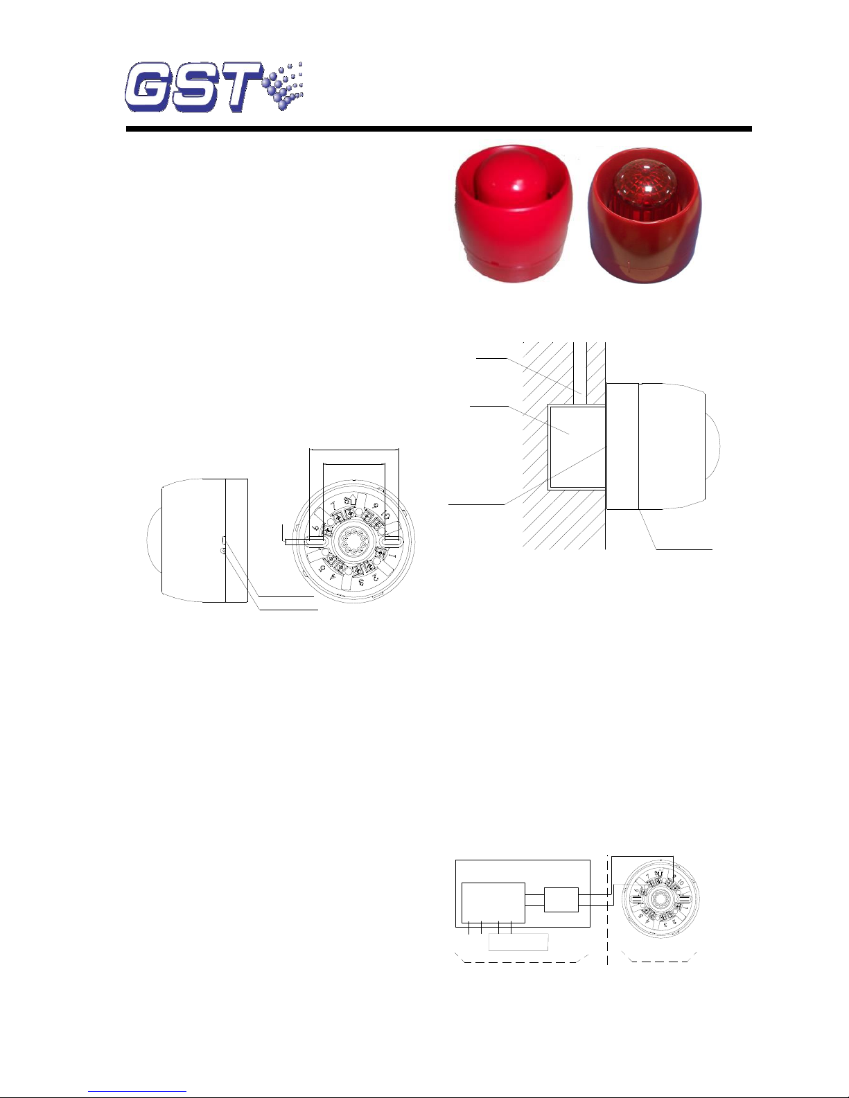
Connection & Wiring
Terminals on the base are shown in Fig. 2.
5mm
55mm
80mm
Arch knock off Hole
G
1
K
1
D
D
2
1
2
Z
2
K
S
Z
Water leak hole
Fig. 1 Fig. 2
D1+ (9), D2- (7): Connected with I-9333 Interface,
polarized.
Intrinsic Safety Parameters for D1/D2: Ui=28V,
Ii=93mA,Ci=0,Li=0,Pi=0.65W
D1 is connected with (3) of the safety barrier and D2
to (4).
Recommended Wiring
Intrinsically safe cable with cross section not less
than 1.5mm2, subject to local codes.。
Installation
Warning: Before installing the device, disconnect
the power from the loop.
Before installation, make sure the enclosure is
in good condition and marking complete.
When the sounder/sounder strobe is surface
mounted, it should be placed 0.2m from the ceiling
for normal space height. When conduit is embedded,
the base can be mounted on the electrical box.
Its mounting method is shown in Fig. 3. Water leak
hold should installed downward.
Conduit
Electrical Box
Wire hole
Water leak hole
should downward
Fig. 3
The base and the sounder/sounder strobe are
twisted together. When mounting, remove the
sounder strobe, thread cables through the cable
entry in the base and connect with corresponding
terminals, then twist the sounder/sounder strobe
onto the base.
If the sounder/sounder strobe is required
anti-removal, knock down the arch knock-off hole as
shown in Fig. 1 and fix it with ST2.9×6.5 tapping
screws (in this case, it must be removed by a special
tool).
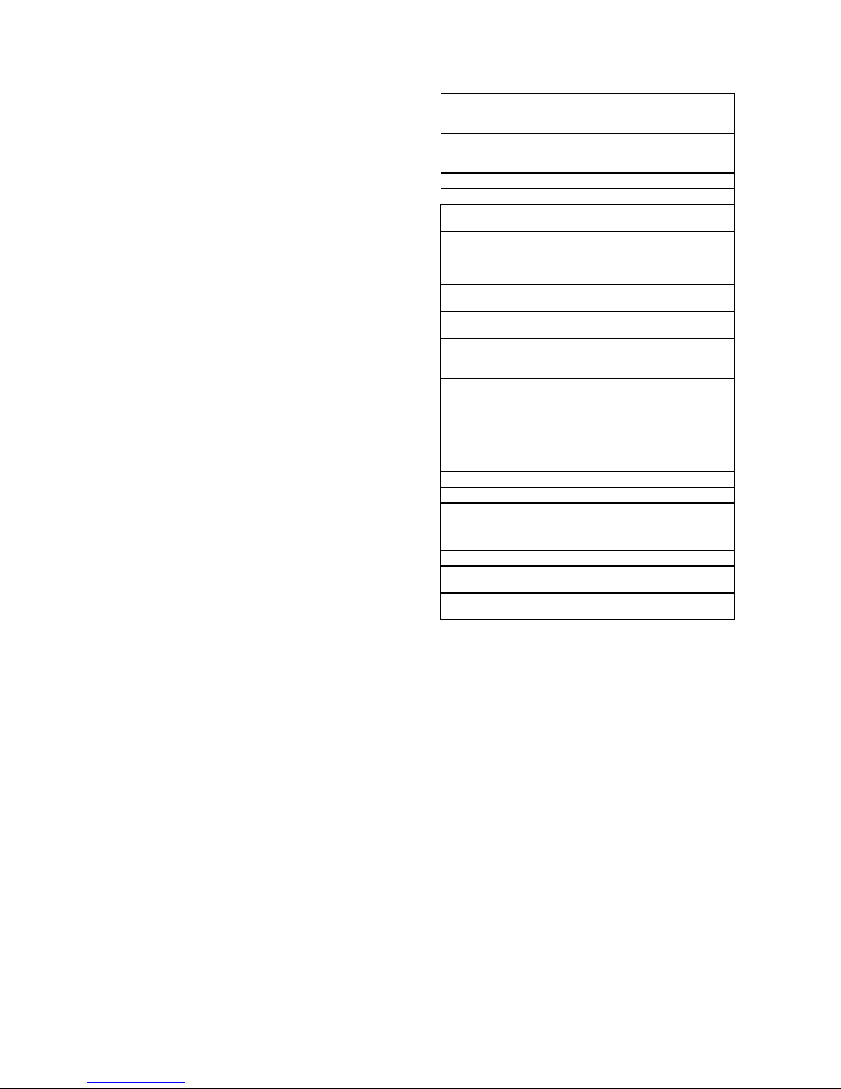
Application
The sounder/sounder strobe can match I-9333
Interface to form an intrinsically safe system. The
system wiring is shown in Fig. 4.
D1 D2 Z1 Z2
I-9333 Circuit
Board
I-9333 Interface
24VDC
Fire Alarm Control Panel
L-
L+
2(-)
1(+)
GST-AS-200 Zener
Safety Barrier
Safety Area
4(-)
3(+)
Hazardous Area
1
Z
2
Z
K
2
S
D
2
G
1
K
D
1
Fig. 4
DC-9404(IS)
Intrinsically Safe Conventional Sounder
DC-9403(IS)
Intrinsically Safe Conventional Sounder Strobe
Page 2
30309767 Issue 1.04
Cautions
1. I-9333 Interface should be installed in safety
area, the wires of "Safety Area" should be
separated from those of "Hazardous Area", and
be kept a certain distance (at least 50mm).
2. The safety barrier should be well grounded.
The screws should not be loose. Ground
resistance should not be over 1Ω. The
parameters assigned in the intrinsically safe
loop should not be over the specified value, that
is, the capacity assigned among cables should
not be over 0.083μF, the inductance assigned
not over 4.1mH.
3. During maintenance, products passing the
explosion-proof test should not be replaced and
parts and structure affecting explosion-proof
functions should not be modified.
Limited Warranty
GST warrants that the product will be free from
defects in design, materials and workmanship during
the warranty period. This warranty shall not apply to
any product that is found to have been improperly
installed or used in any way not in accordance with
the instructions supplied with the product. Anybody,
including the agents, distributors or employees, is
not in the position to amend the contents of this
warranty. Please contact your local distributor for
products not covered by this warranty
Specification
Power Loop
voltage when
activating
24VDC(16VDC~28VDC)
Power Loop
voltage in standby
state
7VDC(5VDC~8VDC)
Standby current
≤5mA
Active current
≤50mA
Wiring
Polarized two-wire with I-9333
Interface
Sound Level
Sound level: 85dB~115dB (A
weighted in 3m front).
Flashing
Frequency
1.4×(1±20%)Hz(DC-9403(IS))
Tone Modification
Period
0.7s±20%
Explosion-proof
marking
ExibⅡCT6 Gb
Explosion-proof
Certificate
Number
CE17.2192 (DC-9404(IS) )
CE17.2190 (DC-9403(IS))
Security Barrier
Parameters
GST-AS-200
U0=28V, I0=93mA
Ingress Protection
Rating
IP33
Operating
Temperature
-10℃~+55℃
Relative Humidity
≤95%, non condensing
Application
Indoor
Material and Color
of Enclosure
ABS, red. 107Ω≤surface
resistance≤109Ω, plexiglass in
front
Dimension (D×H)
ф110mm×95.9mm
Mounting Hole
Spacing
55mm~80mm
Weight
DC-9404(IS):About 312.2g
DC-9403(IS):About 322.2g
.
This Data Sheet is subject to change without notice. Please contact GST for more information or questions.
Gulf Security Technology Co., Ltd.
No. 80, Changjiang East Road, QETDZ, Qinhuangdao, Hebei, P. R. China 066004
Tel: +86 (0) 335 8502434 Fax: +86 (0) 335 8502532
service.gst@fs.utc.com www.gst.com.cn
 Loading...