

Page 1
30309282 Issue 1.05
Features
Integrated algorithm of analyzing fire, recognize black smoke
quickly.
Drift sensitivity, suit to environment extensively.
Removable innovative sensing chamber, easy for maintenance.
The fire LED allows 360°viewing.
Providing remote terminals connect with remote indicator.
Featuring magnetic test.
2-level sensitivities (complying with EN 54-7 just when sensitivity is
level 1).
Description
DC-9102E Conventional Photoelectric Smoke Detector is a
new-generation product. With built-in microprocessor, the detector is
highly fixed with reliable fire judging program, which make it stable and
reliable performance.
When the detector checks fire signal, it will send fire information to the
control panel or addressable zone monitor unit by means of current
changing. The detector keeps turning on the LED to indicate alarm state
until it is reset.
The detector is developed from sensing chamber by scattering theory. It
has the ability to resist dust contamination and environmental light.
The detector utilizes drift compensation algorithm: When the environment
is changing, such as dust accumulation, humidity and temperature
changing, the detector can figure out these drift variation to make up for
sensitivity, thus the amount of smoke needed to generate an alarm
remains constant, irrespective of environmental conditions. The principle
diagram is shown as Fig. 1.
Smoke density Smoke density
A Fixed sensitivity b Environment value after drifting (prone
to nuisance alarm)
c Normal environment value A Variable sensitivity
Fig. 1
Connection and cabling
The orientation base is shown in Fig. 3.
C
B
A
Fig. 2 Fig. 3
There are four terminals with number on the base. “1” is connected with
output anode of addressable zone monitor unit or the anode of the power
supply; “2” is used as output, connected with anode of next detector
(Terminal 1) and also connected with anode of remote indicator; “3” is
connected with output cathode of addressable zone monitor unit or the
cathode of the power supply as well as the cathode of next detector; “4”
connects with the cathode of remote indicator.
Recommended Wiring
1.0mm2 or above fire cable for all terminals laid through metal conduit or
flame proof conduit, subject to local codes.
Note: Different color cables are used to avoid wiring mistake.
Installation
Fix the base with two taping screws. Then align A (Fig.2) on the bottom of
the detector to B (Fig.3) of the base, and rotate the detector clockwise to
mark C.
Mounting of the detector is shown in Fig.4.
Electrical Box
Conduit
Detector
51.5mm
Orientation Base
Fig. 4
Application
Notes: The alarm current depends on the current limit of the control
panel. 24VDC cannot power the detector directly. Otherwise the
detector will be blown up for lack of current limit resistor.
The sensitivity level 1 is defaulted, which can be modified by P-9910B
programmer.
Program sensitivity: In power-on state, input unlocking password and
press Clear to unlock. Press Function, then press “3”, the screen shows
“-” at the last digit. Input corresponding sensitivity or parameter and press
Program, the screen will show a “P”, the corresponding sensitivity or
parameter is programmed. Press Clear to clear the "P". Input locking
password and press Clear to return.
Read sensitivity: On power-on time, press Test, the LCD screen shows
the address of the detector; Press Up, it shows in turn the sensitivity,
device type, initial sensitivity.
The detector is suitable for hotels, restaurants, office buildings, teaching
buildings, banks, warehouses, libraries, computer rooms and switch
rooms, etc.
When the detector connects with conventional fire alarm control
panel or addressable zone monitor unit from GST, and if DP-9907 Active
End of Line Unit is connected to the end of output loop, DB-01D base
should be used.
Used as the detector base, DP-9907 Active End of Line is
used to be installed a conventional detector on it. The system
connection is shown in Fig. 5.
O-
O+
Fig. 5
When DP-9907 Active End of Line Unit is not used as the
detector base, a cover should be added to it. The system
connection is shown in Fig.6.
DC-9102E
Conventional Photoelectric
Smoke Detector
Time
Time
a
b
c
a b c
A
548d/03
0832-CPR-F0003
GST-0007-01
14
Page 2
30309282 Issue 1.05
Fig. 6
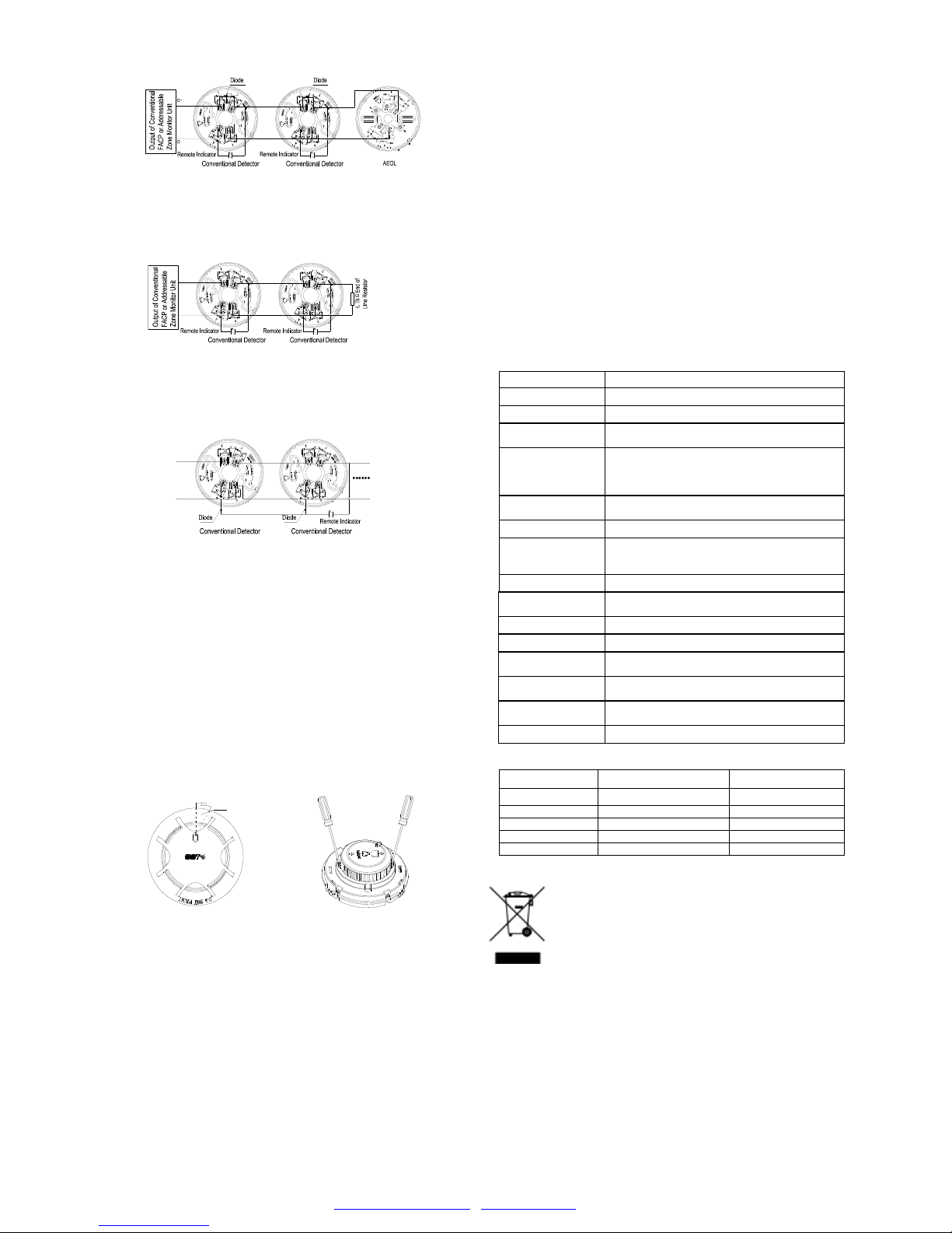
When the detector is connected with conventional fire alarm control
panel or the addressable zone monitor unit from GST, if a 4.7KΩ
terminal resistor is connected to the end of output loop, then DB-01 base
is used. The system connection is shown in Fig. 7.
O-
O+
Fig. 7
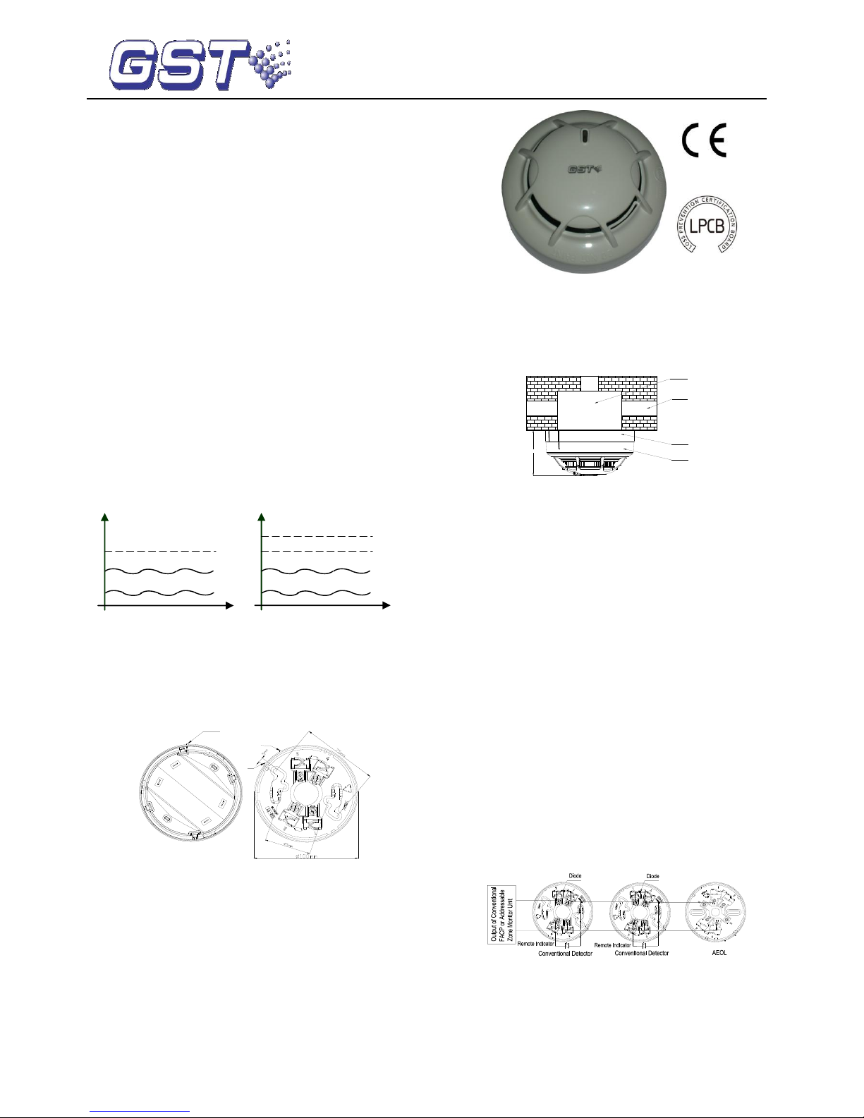
When a remote indicator connects with a few of detectors, a diode
1N5819 needs connecting with Terminal 4 of the orientation base in
series and with anode of the remote indicator. Either DB-01 or DB-01D is
used depends on which DP-9907 Active End of Line Unit or 4.7KΩ
terminal resistor is connected. The system composition is shown in Fig. 8.
O+
O-
Fig. 8
Output loop of the addressable zone monitor unit can be connected with
up to 15 conventional field devices. The addressable zone monitor unit
features loop checking. When the loop is broken, the addressable zone
monitor unit will send fault signal to fire alarm control panel. When any
field device in the output loop is removed, the addressable zone monitor
unit reports fault. If a DP-9907 Active End of Line Unit is connected, it will
not affect the normal operation of other field devices.
Testing
Before testing, please ensure that the detector has been installed
correctly and powered up. After 10 seconds, testing can begin.
1. The detector must be tested after installation and periodical
maintenance.
2. Testing method
1) Magnetic test
Magnetic test zone is shown in Fig. 9. Put the magnet of commission tool
close to that of the detector and hold on for a few seconds until the
detector generates alarm.
Test zone
Fig. 9 Fig. 10
2) Smoke test
Taking a cotton rope burning without flame close to the detector, blow the
smoke into the detector until the detector generates alarm.
3. After testing, cut power for 10 seconds at least and reset the detector.
Notify the proper authorities that the system returns to normal state.
Clean the failure detector in the test according to Maintenance, and test it
again. If it is still fail to pass, please return it to repair.
Maintenance
1. The detector should be installed just before commission and kept well
before installation, taken corresponding measures for dust-proof,
damp-proof and corrosion-proof.
2. The dust cover cannot be removed until the project has been plunged
into usage. Otherwise it can’t alarm normally.
3. Clean the detector at least once a year to ensure normal operation of
the system.
4. If nuisance alarms are often found of the detector on site, the sensing
chamber should be cleaned and replaced when necessary.
a) Open the top cover of detector, and draw out the sensing
chamber by slightly lifting its two sides using a straight
screwdriver, as shown in Fig. 10.
b) Clean the sensing chamber by alcohol cotton swab clipped by
tweezers, and also by clear water and brush. Please note not
to leave any cotton in the chamber.
c) Install the sensing chamber and top cover back.
5. Before cleaning, notify the proper authorities that the system is
undergoing maintenance and will temporarily be out of service. Disable
the zone or system undergoing maintenance to avoid unwanted alarms.
6. The detector should be tested again after cleaning and re-installing.
7. Protect the metal component on the PCB against damp and improper
distortion.
8. Fire simulation test should be made to the detector at least once half a
year.
Specification
Operating Voltage
24VDC(16VDC~28VDC )
Standby Current
≤60μA
Alarm Current
≤55mA
Fire LED
Red, flash in polling and illuminate in
alarming.
Remote indication
output
Polarity-sensitive output, directly connecting
with remote indicator (built in 10k resistor in
series, max. output current is 2mA); don’t
illuminate when in normal; flash in alarming.
Max. ripple
voltage
2V(peak to peak value)
Alarm reset
Instant power down (10s Min, 1.0VDC Max
Sensitivity setting
The sensitivity can be set by hand held
programmer. There are two sensitivity levels:
level 1 (default), level 2.
Wiring
Two-wire, polarity sensitive.
Environment
Temperature
-10℃~+50℃
Relative Humidity
≤95%, non condensing
Material
ABS
Ingress Protection
Rating
IP2X
Dimension
Diameter:100mm Height: 44.5mm (without
base)
Mounting Hole
Spacing
45mm~75mm
Weight
About 110g
Accessories and Tools
Model
Name
Remark
P-9910B
Hand held programmer
Supplied separately
DB-01
Base
Supplied separately
DB-01D
Base
Supplied separately
DP-9907
Active End of Line Unit
Supplied separately
T-MT
Commission tool
Supplied separately
WEEE Information
2012/19/EU (WEEE directive): Products marked with this
symbol cannot be disposed of as unsorted municipal waste
in the European Union. For proper recycling, return this
product to your local supplier upon the purchase of
equivalent new equipment, or dispose of it at designated
collection points.
Limited Warranty
GST warrants that the product will be free from defects in design,
materials and workmanship during the warranty period. This warranty
shall not apply to any product that is found to have been improperly
installed or used in any way not in accordance with the instructions
supplied with the product. Anybody, including the agents, distributors or
employees, is not in the position to amend the contents of this warranty.
Please contact your local distributor for products not covered by this
warranty.
This Data Sheet is subject to change without notice. Please contact GST for more information or questions.
Gulf Security Technology Co., Ltd.
No. 80, Changjiang East Road, QETDZ, Qinhuangdao, Hebei, P. R. China 066004
Tel: +86 (0) 335 8502434 Fax: +86 (0) 335 8502532
service.gst@fs.utc.com www.gst.com.cn
 Loading...