

Page 1
30309534 Issue 1.04
Features
Strong environmental adaptability due to drift compensation. .
Reed switch testing.
Removable innovative sensing chamber, easy for
maintenance.
Fire LED allows 360°viewing.
Remote indicator output available.
2 levels sensitivities programmable; fix temperature or rate of rise
programmable.
2 levels smoke sensitivities programmable, level 1 complies with
EN 54-7. Heat part complies with EN 54-5.
Description
DC-9101E Conventional Combination Heat Photoelectric Smoke
Detector, non-addressable, is a kind of combination detector consisting of
smoke sensing parts and semi-conductor heat sensing parts in
technological structure and circuit structure.
Together with DP-9907, it can connect to conventional fire alarm control
panel or connect with intelligent fire alarm control panel through I-9319
Addressable Zone Monitor Unit conduct the processing of detector
signals. The detector has the advantages of both conventional
photoelectric detector and rate of rise and fixed temperature heat detector.
Just because of the combination of smoke detector and heat detector, it
overcomes the non-sensitivity to dark smoke particles of ordinary
scattering photoelectric detectors. It can also pick up fire with obvious rise
of temperature such as alcohol flame, thus extending the application
range.
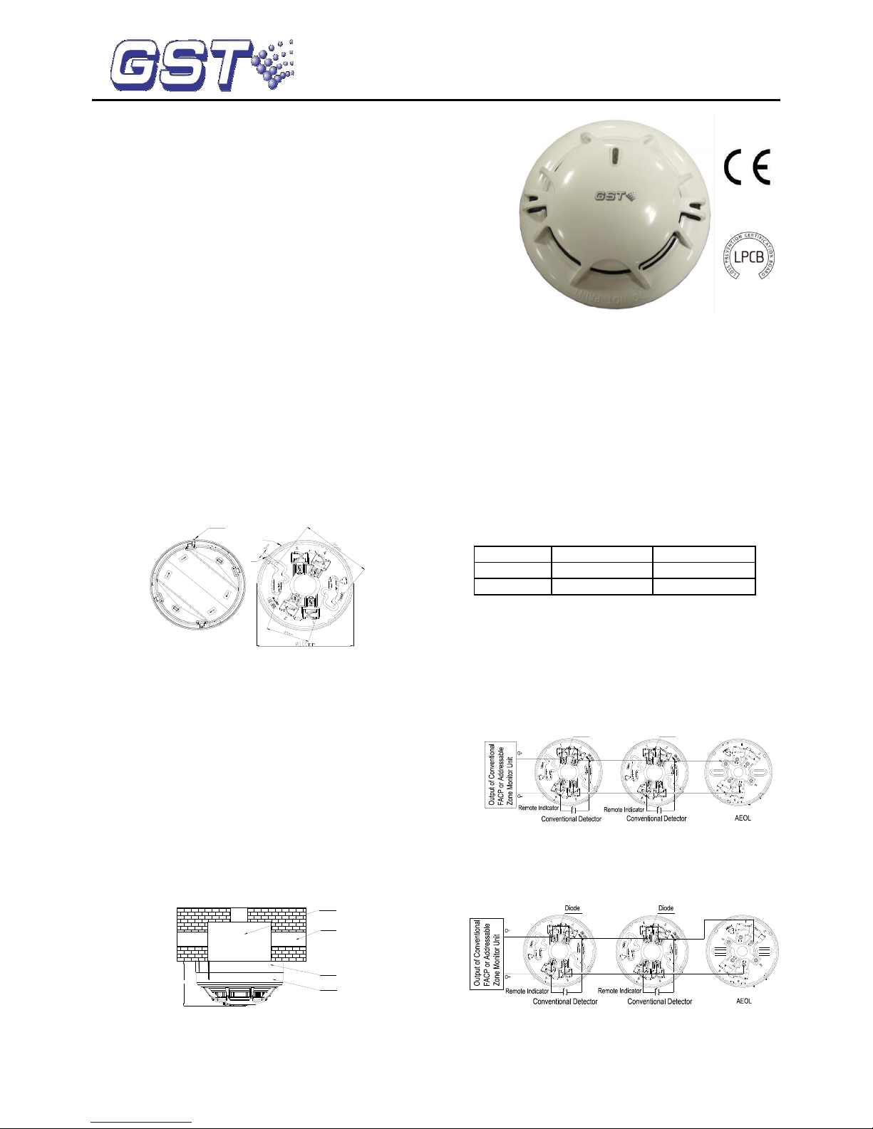
Connection and cabling
The base is shown in Fig. 2.
C
B
A
Fig. 1 Fig. 2
There are four terminals with numbers on the base.
1: Detection zone positive IN
2: Detection zone positive OUT
3: Detection zone negative IN and OUT
2: Positive terminal of remote indicator
4: Negative terminal of remote indicator
Recommended Wiring
1.0mm2 or above fire cable for all terminals laid through metal conduit or
flame proof conduit, subject to local codes.
Note: Different color cables are used to avoid wiring mistake.
Installation
Fix the flame retardant base with two taping screws. Then align A on the
bottom of the detector to B of the base, and rotate the detector clockwise
to mark C (Refer to Fig.1 and Fig. 2 for mark A, B, C).
Mounting of the detector is shown in Fig.3.
Electrical Box
Conduit
Detector
51.5mm
Orientation Base
Fig. 3
Application
Warning: The alarm current depends on the current limit of the
control panel. 24VDC cannot power the detector directly. Otherwise
the detector will be blown up for lack of current limit resistor.
The sensitivity level 1 is defaulted, which can be modified by P-9910B
programmer. Refer to P-9910B Hand Held Programmer Installation and
Operation Manual for details.
In power-on state, input unlocking password and press Clear to unlock.
Press Function, then number “3”, the screen shows “-” at the last digit.
Input corresponding sensitivity or parameter and press Program, the
screen will show a “P”, the corresponding sensitivity or parameter is
programmed. Press Clear to clear the "P". Input locking password and
press Clear to return.
Rate of rise and level 1 is defaulted.
Parameters set using programmer
Input Number
Smoke Sensitivity
Heat Sensitive
1
Level 1
Rate of rise
2
Level 2
Rate of rise
Read Sensitivity Level: in power-on state, pressing Test,the screen
displays address of the detector. Pressing “Up”, display sensitivity level,
device type and initial sensitivity in turns.
When the detector connects with conventional fire alarm control
panel or addressable zone monitor unit from GST, and if DP-9907 Active
End of Line Unit is connected to the end of output loop, DB-01D base
should be used.
Used as the detector base, DP-9907 Active End of Line is
used to be installed a conventional detector on it. The system
connection is shown in Fig. 4.
Fig. 4
When DP-9907 Active End of Line Unit is not used as the
detector base, a cover should be added to it. The system
connection is shown in Fig.5.
Fig. 5
When the detector is connected with conventional fire alarm control
DC-9101E Conventional Combination
Heat Photoelectric Smoke Detector
0832-CPR-F0338
GST-0507-01
14
548q/03
Page 2
30309534 Issue 1.04
panel or the addressable zone monitor unit from GST, if a 4.7KΩ
terminal resistor is connected to the end of output loop, then DB-01 base
is used. The system connection is shown in Fig. 6.
Fig. 6
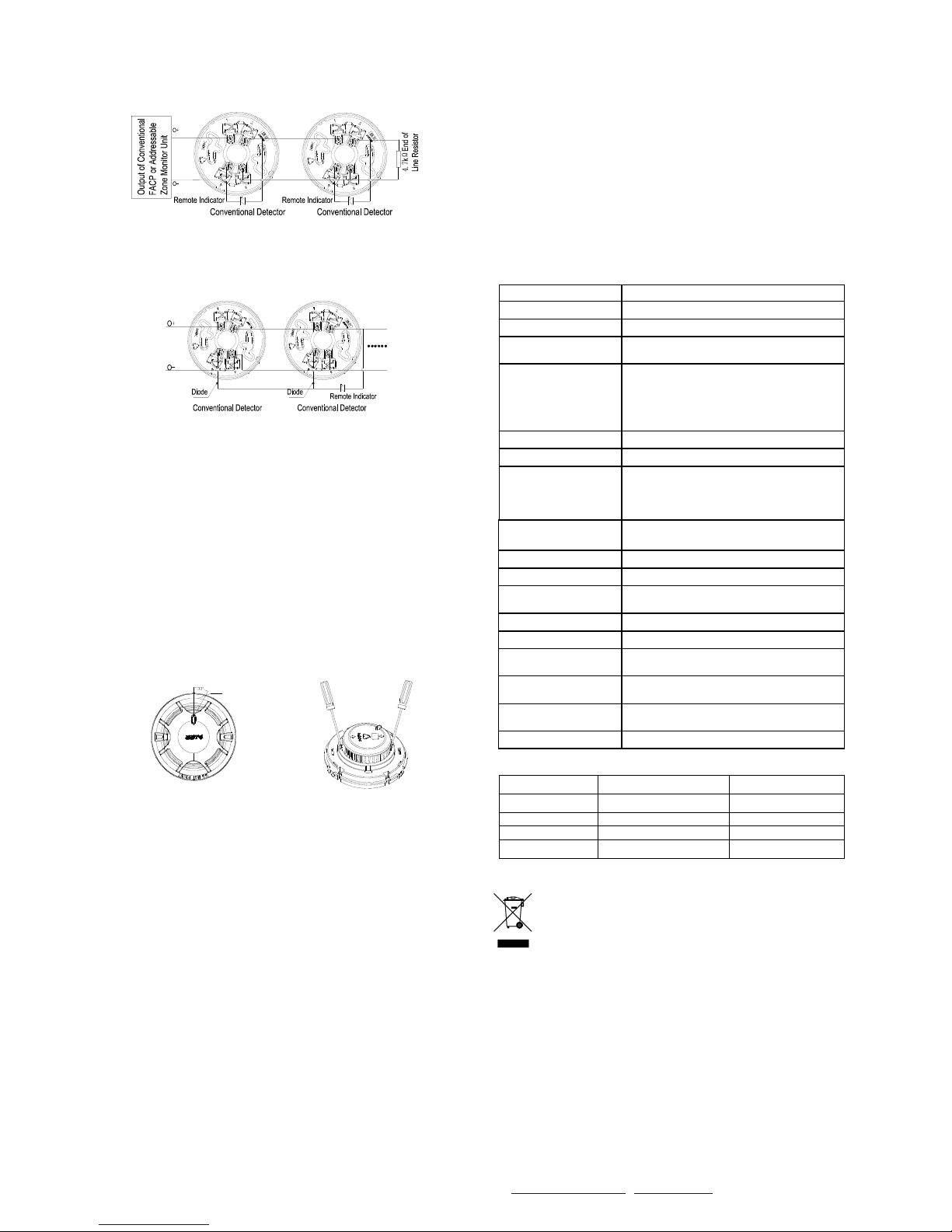
When a remote indicator connects with a few of detectors, a diode
1N5819 needs connecting with Terminal 4 of the orientation base in
series and with anode of the remote indicator. The system connection is
shown in Fig. 7.
Fig. 7
Output loop of the addressable zone monitor unit can be connected with
up to 15 conventional field devices. The addressable zone monitor unit
features loop checking. When the loop is broken, the addressable zone
monitor unit will send fault signal to fire alarm control panel. When any
field device in the output loop is removed, the addressable zone monitor
unit reports fault. If a DP-9907 Active End of Line Unit is connected, it will
not affect the normal operation of other field devices.
Testing
Before testing, please ensure that the detector has been installed
correctly and powered up. After 10 seconds, testing begins.
1. The detector must be tested after installation and periodical
maintenance.
2. Testing method
1) Magnetic test
Test zone is shown in Fig. 8. Put the magnet of commission tool close to
that of the detector and hold on for a few seconds until the detector
generates alarm.
Test Zone
Fig.8 Fig.9
2) Smoke test
Taking a cotton rope burning without flame close to the detector, blow the
smoke into the detector until the detector generates alarm.
3) Temperature test
Approach a heater (such as a hair drier) to the thermistor of the detector
until it alarms.
3. After testing, cut power for 10 seconds at least and reset the detector.
Notify the proper authorities that the system returns to normal state.
Clean the failure detector in the test according to Maintenance, and test it
again. If it is still fail to pass, please return it to repair.
Maintenance
1. The detector should be installed just before commission and kept well
before installation, taken corresponding measures for dust-proof,
damp-proof and corrosion-proof.
2. The dust cover cannot be removed until the project has been plunged
into usage. Otherwise it can’t alarm normally.
3. Clean the detector at least once a year to ensure normal operation of
the system.
4. If nuisance alarms are often found of the detector on site, the sensing
chamber should be cleaned and replaced when necessary.
a) Open the top cover of detector, and draw out the sensing
chamber by slightly lifting its two sides using a straight
screwdriver, as shown in Fig. 9.
b) Clean the sensing chamber by alcohol cotton swab clipped by
tweezers, and also by clear water and brush. Please note not
to leave any cotton in the chamber.
c) Install the sensing chamber and top cover back.
5. Before cleaning, notify the proper authorities that the system is
undergoing maintenance and will temporarily be out of service. Disable
the zone or system undergoing maintenance to avoid unwanted alarms.
6. The detector should be tested again after cleaning and re-installing.
7. Fire simulation test should be made to the detector at least once half a
year.
Specification
Operating Voltage
24VDC(16VDC~28VDC)
Standby Current
≤60μA
Alarm Current
≤55mA
Fire LED
Red, flash in polling and illuminate in
alarming.
Remote indication
output
Polarized output. Directly connect to
remote indicator (built in 10k
resistor in series, output current is
2mA); Flash in alarming and do not
illuminate in normal.
Max. ripple voltage
2V(peak to peak value)
Alarm reset
Instant power down (2s Min, 1.0VDC Max)
Wiring
Two-wire, polarity sensitive. When the
polarity is reversed, the detector can give
alarm but the remote indicator doesn’t
work normally.
Setting of sensitivity
and range
The sensitivity can be set by programmer
with two levels: Level 1(default), level 2.
Detector Class
A2R
Action Temperature
62℃
Environment
Temperature
-10℃~+50℃
Relative Humidity
≤95%, non condensing
Material of Enclosure
ABS
Ingress Protection
Rating
IP2X
Dimension
Diameter:100mm Height: 54.5mm (with
base)
Mounting Hole
Spacing
45mm~75mm
Weight
About 110g
Accessories and Tools
Model
Name
Remark
P-9910B
Hand held programmer
Supplied separately
DB-01
Base
Supplied separately
DB-01D
Base
Supplied separately
T-MT
Commission tool
Supplied separately
WEEE Information
2012/19/EU (WEEE directive): Products marked with this
symbol cannot be disposed of as unsorted municipal waste in
the European Union. For proper recycling, return this product
to your local supplier upon the purchase of equivalent new
equipment, or dispose of it at designated collection points.
Limited Warranty
GST warrants that the product will be free from defects in design,
materials and workmanship during the warranty period. This warranty
shall not apply to any product that is found to have been improperly
installed or used in any way not in accordance with the instructions
supplied with the product. Anybody, including the agents, distributors or
employees, is not in the position to amend the contents of this warranty.
Please contact your local distributor for products not covered by this
warranty.
This Data Sheet is subject to change without notice. Please contact GST for more information or questions.
Gulf Security Technology Co., Ltd.
No. 80, Changjiang East Road, QETDZ, Qinhuangdao, Hebei, P. R. China 066004
Tel: +86 (0) 335 8502434 Fax: +86 (0) 335 8502532 service.gst@fs.utc.com www.gst.com.cn
 Loading...