

Page 1

Page 2

D-9107RExd
Digital Flame Proof Dual IR Flame Detector
Installation and Operation Manual
Page I
CONTENTS
1 Overview .................................................................................................................. 1
2 Specification ............................................................................................................ 1
3 Construction and Operation Principle ................................................................... 2
3.1 Construction ........................................................................................................ 2
3.2 Adjustment Frame ............................................................................................... 3
3.3 Operation Principle ............................................................................................. 3
4 Installation and Connection ................................................................................... 3
4.1 Installation ........................................................................................................... 3
4.2 Connection.......................................................................................................... 4
5 Testing ...................................................................................................................... 6
6 Operation ................................................................................................................. 6
7 Application ............................................................................................................... 7
8 Troubleshooting ...................................................................................................... 7
9 Maintenance............................................................................................................. 8
10 Caution ................................................................................................................... 8
11 Accessories ........................................................................................................... 8
Page 3
D-9107RExd
Digital Flame Proof Dual IR Flame Detector
Installation and Operation Manual
Page 1
1 Overview
Dual-band infrared light detection for fire alarm.
Sensitive to flame from material containing carbon. Suitable for fire happen with
flame at the start.
Addressable (connecting GST fire alarm control panel) and non-addressable
(through relay contact) working modes optional.
Flame-proof. Applicable to either commercial or hazardous industrial areas, such
as explosive Zone 1 and 2, and flammable dust atmosphere.
2 Specification
Operating Voltage:
Loop 24V come from control panel Z1,Z2 terminals(addressable mode
application) or power supply(non-addressable mode application)
24VDC come from 24VDC power supply
Operating Current:
Loop: Standby current≤1mA, alarm current≤1mA, Maximum Consumption
28mW
24VDC: Standby current≤20mA, alarm current≤30mA, Maximum
Consumption:840mW
Classifications:
The detector has 3 classifications. The factory default sensitivity is class 1,
which can be reduced in field using GST handheld programmer.
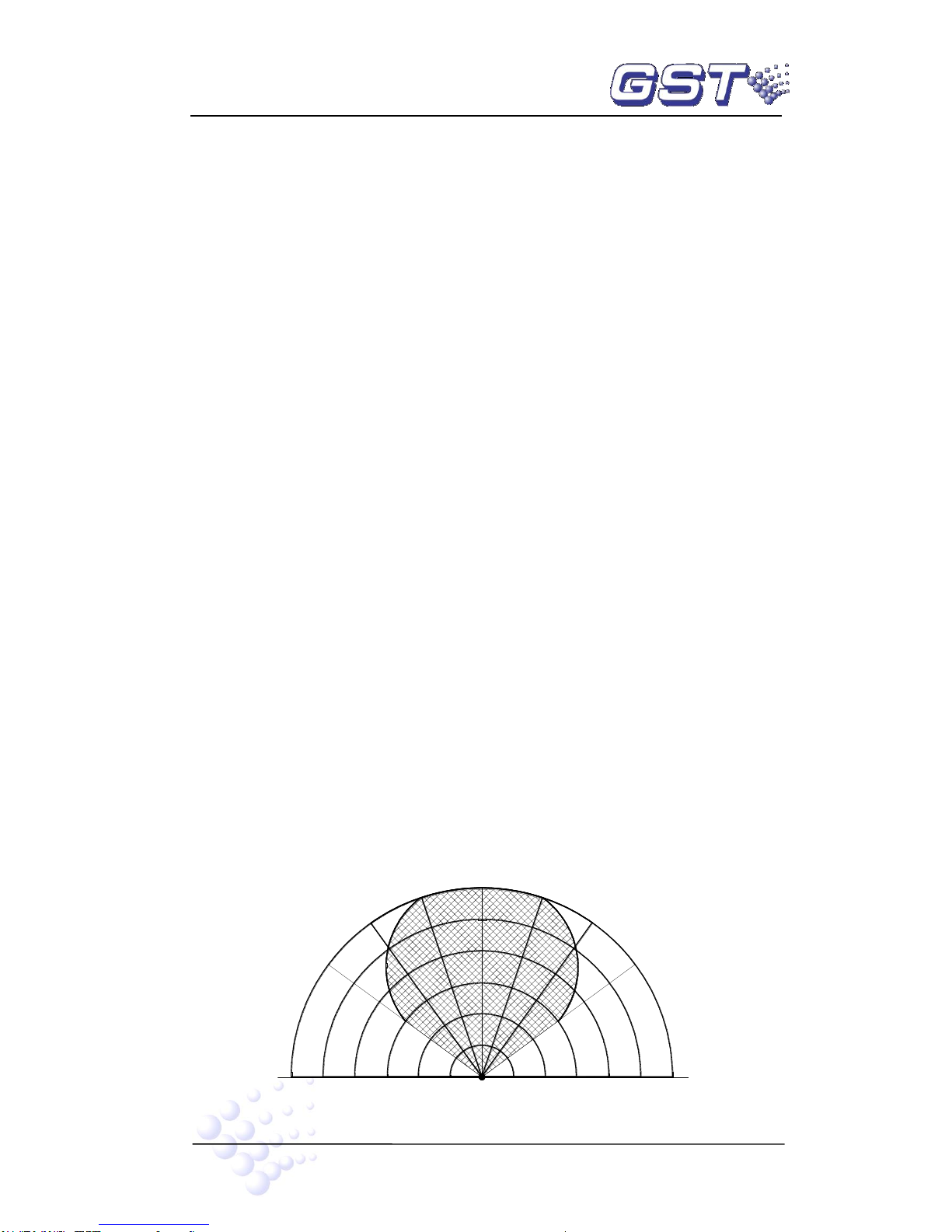
Detection Distance:
Class 1 : 25m (furthest)
Class 2: 17m
Class 3: 12m
Test Fire: 33cm×33cm n-heptane fire.
The correlation between detection distance and angle is shown in Fig. 1. The
shaded area is detectable.
The semicircle in the figure represents the detection distance in percentage.
100%
50%
15
30
15
45
30
0
45
Detector
furthest
50%
100%
o
o
o
o
o
o
o
Fig. 1
Page 4
D-9107RExd
Digital Flame Proof Dual IR Flame Detector
Installation and Operation Manual
Page 2
Note: The detection angle to all directions are the same. Fig. 1 only gives a section
illustration.
Response Spectral Range: 4.4μm±0.5μm
Response Time ≤30s
Indicators:
In addressable mode and non-addressable mode ,
Red LED: Flashes periodically in standby state, and steadily illuminates in fire
alarm.
Yellow LED: Off in standby state, and steadily illuminates in fault.
Contact Output:
Fire alarm contact: 1A/25VDC, normally closed in fire alarm, and normally
open in other states.
Fault contact: 1A/25VDC, normally open in fault state, and normally closed in
other states.
Operating Environment:
Temperature: -20℃~+55℃
Relative Humidity: ≤95%, non-condensing
Ingress Protection: IP65
Dimensions: 166mm×235mm×199mm (with adjustment frame)
Installation Hole Space: 125.5mm×80mm
Installation Hole for Cable Entry: M27×2
Material and Color of Enclosure: Stainless steel, metallic grey
Weight:
Detector: 4.8kg
Adjustment frame: 1.3kg
Explosion-proof Mark: Exd IIC T6 Gb/Ex tb IIIC T85℃ Db
Explosion-proof Certificate Number: Presafe 14 ATEX 5548X
Standard: EN60079-0:2009,EN60079-1:2007,EN60079-31:2009
3 Construction and Operation Principle
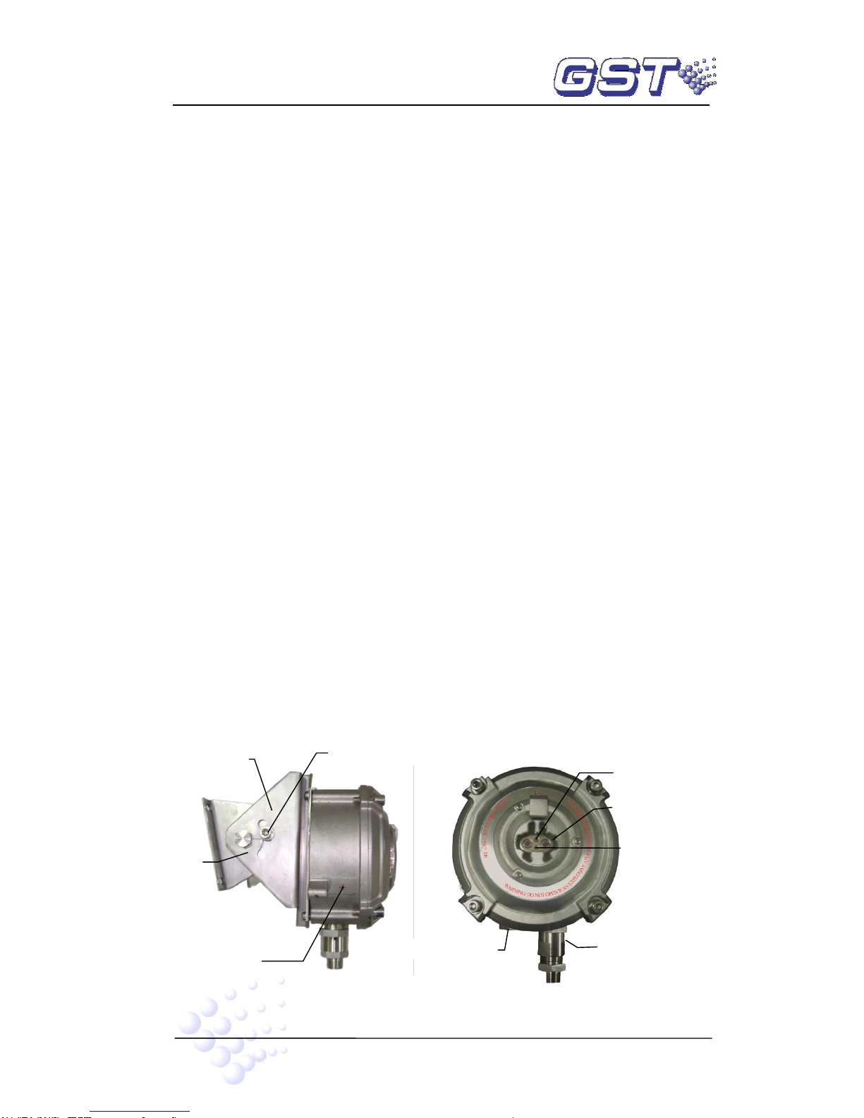
3.1 Construction
The construction of the detector is shown in Fig. 2.
Fig. 2
Adjustment
Frame
Securing Bolt
Earth
Axes
Fire LED
Detection
Cable Junction
Blanking element
Fault LED
Page 5

D-9107RExd
Digital Flame Proof Dual IR Flame Detector
Installation and Operation Manual
Page 3
3.2 Adjustment Frame
The adjustment frame can rotate by 60°around the axe, as shown in Fig. 3.
Fig. 3
3.3 Operation Principle
The detector uses two pyroelectric infrared sensors to detect the change of light signal
of flame and background light signal at two bands of infrared spectrum through two
signal processing channels. Its microprocessor analyzes the signal through the flame
channel and background channel to judge if there is flame.
4 Installation and Connection
4.1 Installation
Before installation, check first if the enclosure is in good condition with all necessary
markings. Then set the detector address and classifications (please refer to Section 6
Operation), and then install it according to Fig. 4.
Fig. 4
Wall
Base
Frame
Bolt
M5 screw
cover
hexagon socket cap
screws M8
×
25
Step 1
Step 2
Step 3
Step 4
Page 6

D-9107RExd
Digital Flame Proof Dual IR Flame Detector
Installation and Operation Manual
Page 4
Step 1: Install the adjustment frame.
Fix the adjustment frame securely on the wall using 4 M6 expansion bolts.
Step 2: Install the base.
Remove the protective cover (Fig. 5) from the base leaving the screws and washer with
the base, and install the base onto the adjustment frame using a M5 screw.
Fig. 5
Step 3: Cable connection. Pleaser refer to “Connection” section.
Step 4: Install the cover. Remove the protective washer, insert the ribbon cable to XT3 of
the base circuit, and then install the enclosure onto the base with reference to the
aligning element with the U-shaped slot and secure the four screws using an Allen key.
Note: The base and enclosure shall be securely installed. There shall not be any
scratches or cracks on the detection window. The enclosure shall be earthed.
Fig. 6
Finally, adjust the frame to make sure the detection window is facing the protected area,
and fix the screws after adjustment.
Note: The detector shall be installed in compliance with relative installation
codes and make sure the enclosure is in good condition. Please always contact
your installer in case of any off-normal condition. Never conduct maintenance or
repair with the power on.
4.2 Connection
(1) It is recommended to use multi-core copper cable with core cross
section≥1.0mm
2
, and external diameter 8mm~10mm.
(2) The cable shall meet field requirements on resistance to explosion, heat,
Aligning Element
Protective Cover
U-shaped slot
Protective washer
Page 7

D-9107RExd
Digital Flame Proof Dual IR Flame Detector
Installation and Operation Manual
Page 5
corrosion and fire.
(3) The cable layout for hazardous explosive area must comply with
corresponding codes. The connecting cable can be copper-core screened
cable or explosion-proof hose with suitable junction thread matching with the
detector taper thread of the cable nut (Fig. 7).
(4) The cable must enter the detector through the junction nut, and there must be
an O-ring, a seal and a washer, as shown in Fig. 7.
Fig. 7
(5) Connect the screen cover of the cable with the protective earth inside the
detector.
(6) Terminals on the base are shown in Fig. 8.
FT1 FT2 AL1 AL2
Fig. 8
Z1, Z2: Communication loop input from fire alarm control panel. Polarity
insensitive.
D1, D2: 24VDC power input. Polarity insensitive.
AL1, AL2: Fire alarm contact output. Normally open contact. Closed in fire
alarm.
FT1, FT2: Fault contact output. Normally closed contact. Open in fault.
The loop cable and the power shall enter the detector through a cable nut, and the
signal cable through another cable nut (Fig. 9). If no signal cable is needed, the cable
outlet shall be inserted with an blanking element with O-ring.
If Z1 and Z2 does not connect with the loop, they must be connected with D1 and D2
polarity-insensitively.
Page 8

D-9107RExd
Digital Flame Proof Dual IR Flame Detector
Installation and Operation Manual
Page 6
Fig. 9
(7) After connection, screw down the cable nut.
5 Testing
Warning: Power up only after all detectors are installed.
1 The detector must be tested after installation and regular maintenance.
2 Tests:
(1) Connect the detector to loop and 24VDC, it should be able to be registered by
the control panel, and the red LED should flash periodically. After the detector
is powered up for 20 minutes, igniting an infrared light source at 1.5m distance
in front of it, it shall report a fire alarm to the control panel within 30s and light
the fire LED, and it should be reset from the control panel to standby state.
(2) Connect the detector to 24VDC only, the red LED should flash periodically in
standby state. After the detector is powered up for 20 minutes, igniting an
infrared light source at 1.5m distance in front of it, it shall give fire signal within
30s and light the fire LED.
3 After testing, reset the detector from control panel if it connects to the loop. If it’s not
connected to loop, disconnect 24VDC power and re-power it up. Notify the proper
authorities the system is back in operation.
4 If a detector fails in testing, clean and test it again. If it still fails, return it for repair.
6 Operation
1 The address and classifications can be programmed using a handheld programmer.
Please refer to the manual for the programmer.
The range of address is 1~242.
For setting classifications, number 1 represents class 1, number 2 for class 2 and
number 3 for class 3.
2 If the detector connects with the loop, it needs to be programmed with an address
to be identified by the control panel. If it doesn’t connect with the loop, no address
setup is required. But terminal Z1 and Z2 must be connected with D1 and D2 in an
Contact Signal cable outlet
Loop and 24VDC cable inlet
NPT 1/2
M24×1.5
Threaded entry type:M27×2
Page 9

D-9107RExd
Digital Flame Proof Dual IR Flame Detector
Installation and Operation Manual
Page 7
polarity-insensitive way.
7 Application
1 Fig. 10 shows the connection of the detector with GST fire alarm control panel.
Fig. 10
2 Connection of the detector with control panels of other suppliers are shown in Fig. 11.
Infrared Flame Detector
Power
Fire Alarm
Signal Input
Fault Signal
Input
AL2
AL1
FT2
FT1
Z2
Z1
D2
D1
Control Unit
Fig. 11
8 Troubleshooting
Possible Problem
Resolution
The indicator doesn’t flash
Check the cable connection. If there is no problem,
replace the detector.
Incorrect contact signal
Registration failure
Other problems
D1
D2 Z1 Z2
FT1
FT2
AL1
AL2
Fire Alarm Control Panel
Power
Loop
Infrared Flame Detector
Page 10

D-9107RExd
Digital Flame Proof Dual IR Flame Detector
Installation and Operation Manual
Page 8
9 Maintenance
1 The detection window should be cleaned at least every three months.
2 Before cleaning, notify relative departments that the system is undergoing
maintenance and will be out of service. Disable the zone or system in maintenance
to avoid unwanted alarms.
3 After cleaning, install the detector back and test again.
10 Caution
(1) The detector should be handled with care during maintenance to avoid damage.
(2) Installation and maintenance should strictly comply with relative codes for
explosive and hazardous areas.
(3) Never open the cover for maintenance in field.
(4) The enclosure must be earthed.
(5) False alarms may occur if there is arc welding operation within 5 meters to the
detector.
(6) The following places are not suitable for the detector:
Where flameless fires are to be expected.
Where intensive smoke spreads before flames.
Where the "view" of the detector is easy to be obscured.
Where the sun can directly shine the detection window.
Where the detector may encounter frequent vibration.
(7) Special conditions for safe use:Repairs of the flameproof joints must be made in
compliance with the structural specifications provided by the manufacturer. Repairs
must not be made on the basis of values specified in tables 1 and 2 of IEC 60079-1.
(8) The screws used for the assembly must be of yield stress higher or equal to
700N/mm2.
(9) The threaded entries comply with following parameters:
Threaded entries type: M27×2
Position on the equipment: see Fig 9
The number permitted: one is installed in back cover, and two at most
Sealing and washer size: Sealing and washer size: 11mm(internal diameter)
×21mm(external diameter)×22mm(thickness)
Cable external diameter 8mm~10mm is recommended.
The torque for cable nut is 25 N.m to compress sealing ring.
(10) One blanking element of threaded entries type M27×2 is delivered with the
detector and installed in back cover.
11 Accessories
1 installation and operation manual
4 M6×60 expansion bolts
1 M5×10 screws
1 adjustment frame
1 Allen Key
Page 11

Gulf Security Technology Co., Ltd.
No. 80, Changjiang East Road, QETDZ, Qinhuangdao, Hebei,
P. R. China 066004
Tel: +86 (0) 335 8502434
Fax: +86 (0) 335 8502532
service.gst@fs.utc.com
www.gst.com.cn
 Loading...