

Page 1
Page 2

D-9105RExd
Digital Flame Proof Reflective Beam Detector
Installation and Operation Manual The Intelligent Solution
CONTENTS
I Overview........................................................................................1
II Features.........................................................................................1
III Technical Specifications.................................................................2
IV Structure and Operation Principle..................................................4
V Mounting and Wiring...................................................................... 5
VI Commission .................................................................................13
VII Operation .....................................................................................15
VIII Troubleshooting ...........................................................................17
IX Maintenance.................................................................................19
X Caution.........................................................................................19
XI Accessories..................................................................................20
Page 3

D-9105RExd
Digital Flame Proof Reflective Beam Detector
Installation and Operation Manual The Intelligent Solution
1
I Overview
D-9105RExd Digital Flame Proof Reflective Beam Detector is able to
output signal in two ways: loop output and contact output. When the
detector is connected with GST fire alarm control panel, information
between the detector and the control panel is transmitted through the
detection loop. The detector address can be programmed ranging from
1 to 242 using GST programmer. When the detector is not connected
with the control panel, fire and fault information can be transmitted
through contacts.
The detector must be used together with a reflector. The number of
reflector(s) to be used (one or four) depends on the distance from the
detector.
With excellent built-in microprocessor, the detector has strong ability of
analysis and judgment.The detector can carry out system commission,
compensation of environmental variation, and judgment of fire and fault
through fixed algorithm. Digital bus technology ensures quick and
complete information transmission. With new and reasonable design,
flexible judgment and precise alignment, it’s aesthetically pleasing and
easy to install and adjust. Its sensitivity can be set with hand held
programmer in field, decreasing the demand for cleanliness of field
conditions, and enlarging application areas.
The detector is applicable to either commercial areas or hazardous
industrial areas, such as Zone 1 and 2 of explosive gas areasand Zone
21 and 22 of combustible dust areas.
II Features
1. Wide operating voltage range, large monitoring areas.
2. Combination of transmitter and receiver ensures easy installation
and accurate optical pathway.
Page 4

D-9105RExd
Digital Flame Proof Reflective Beam Detector
Installation and Operation Manual The Intelligent Solution
2
3. Built-in microprocessor enables intelligent judgment of fire alarm
and fault.
4. The detector can calibrate automatically, which ensures one
person to complete adjustment in short time. It’s also convenient to
operate.
5. Self-diagnosis function can monitorfault with itself.
6. Automatic compensation for factors weakening received signals,
such as a certain amount of dust contamination, positional
excursion and ageing transmitter.
7. Compatible to digital bus protocol, easy to control and operate.
8. Electronically addressed.The address can be programmed in field.
9. Two sensitivity levels can be set in field.
10. The detector’s optical pathway is designed with strong
anti-interference ability.
11. SMT processing technology.
12. Attractive and decent appearance.
III Technical Specifications
1. Operating Voltage:Power supply voltage 15VDC~28VDC
Loop voltage 15V~28V
2. Operating Current:
Power current: Commission current ≤20mA
Standby current ≤12mA
Alarm current ≤22mA
Loop current≤2mA
3. Fire, fault contact output:
Fire relay: contact capacity is 28V/2A. Normally open in normal
state, closed in fire condition.
Fault relay: contact capacity is 28V/2A. Normally open in normal
state, and closed in fault condition.
Page 5

D-9105RExd
Digital Flame Proof Reflective Beam Detector
Installation and Operation Manual The Intelligent Solution
3
4. AdjustmentAngle: Vertical ±30 degrees, horizontal ±45 degrees
5. Maximum angular misalignment: ±0.5°
6. Sensitivity Level:
Level 1: high sensitivity
Level 2: low sensitivity
7. Indication of Detector State:
Commission: Green LED and yellow LED illuminatesorflashes in
a certain way. Refer to Section VI Commission for details.
Normal monitoring state: Red LED flashes periodically.
Fire: Red LED illuminates and fire output contact is closed when
the detector reports fire alarm. The fire signal can be transmitted to
the control panel through loop and has to be cleared by the control
panel. If it’s not connected with GST fire alarm control panel, the
fire signal has to be cleared by rebooting.
Fault: Yellow LED illuminates. The detector clears the fault signal
automatically if the fault condition disappears.
Optical pathway is obscured totally:the detector first gives fault
signal, turns on yellow LED and closes fault relay. 20 secondslater,
it reportsfire alarm, turns on red LED and closes fire relay. Yellow
LED is turned off,fault relay is disconnected. Note: In this case, it
does not necessarily mean there is a fire. After the
obscuration is removed, the detector clears the fault signal
automatically.
8. Operating Environment:
Temperature: -20C~+40C
Relative Humidity≤95%, non condensing
9. MonitoringArea: Maximum monitoring area: 14×100=1400m
2
Maximum width: 14m
10. Length of Optical Pathway:8m~100m
11. Ingress Protection Rating: IP66
12. Dimensions:
Page 6
D-9105RExd
Digital Flame Proof Reflective Beam Detector
Installation and Operation Manual The Intelligent Solution
4
Length: 344mm
Width: 240mm
Depth: 212mm(with adjustment frame)
13. Material and Color of Enclosure: Stainless steel, metallic gray
14. Weight: Detector: 6kg Adjustment frame: 3.8kg
15. Mounting Hole Spacing:
Spacing for embedding: 70mm x 50mm
16. Explosion-proof mark: ExdIICT6/DIPA21TA,T6
IV Structure and Operation Principle
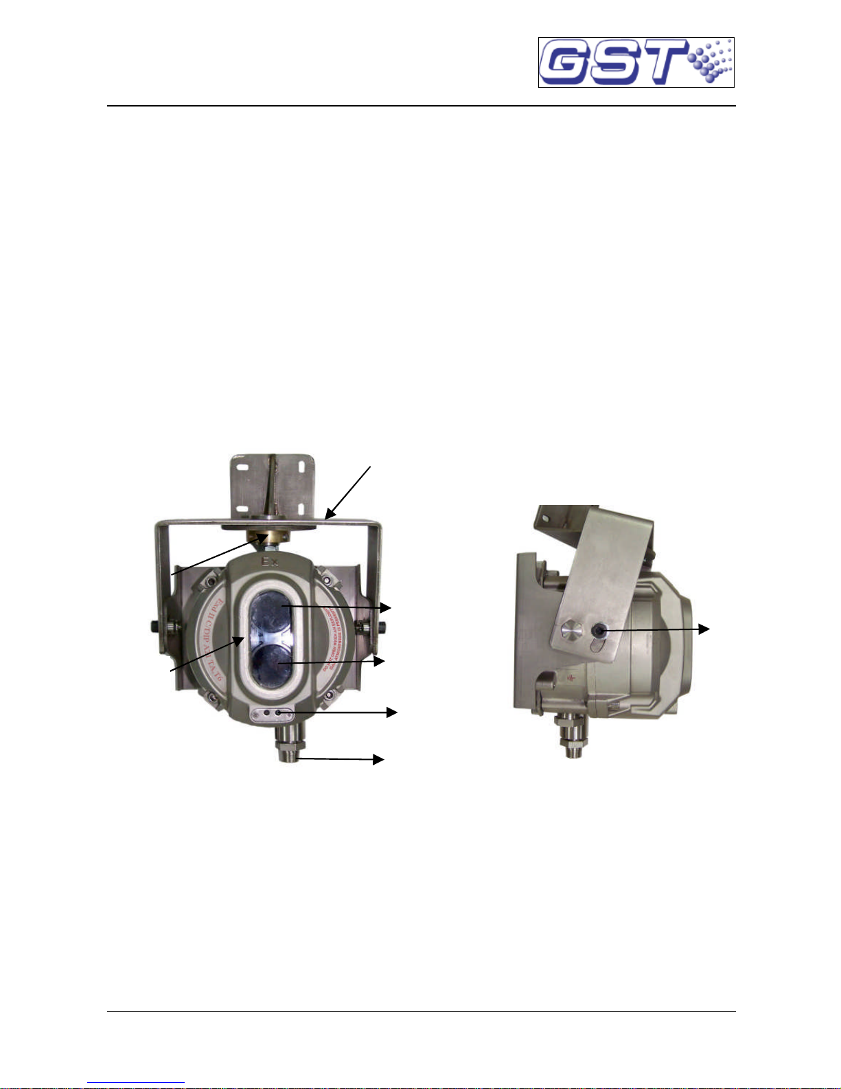
1. Appearance of the detector is shown in Fig. 1.
Fig. 1
2. Operation Principle
The detector and reflector are placed oppositely. The detector includes
a transmitter and a receiver. Infrared beam of certainintensity sent out
from the transmitter is reflected by the right-angle prisms of the reflector,
and then received by the receiver. The receiversimultaneously collects
and amplifies the returned infrared beam, analyze and judge the
Adjustment
Frame
Screw
Receiving
Window
Transmitting
Window
Detector
Wiring Hole
LED
Screw
Page 7
D-9105RExd
Digital Flame Proof Reflective Beam Detector
Installation and Operation Manual The Intelligent Solution
5
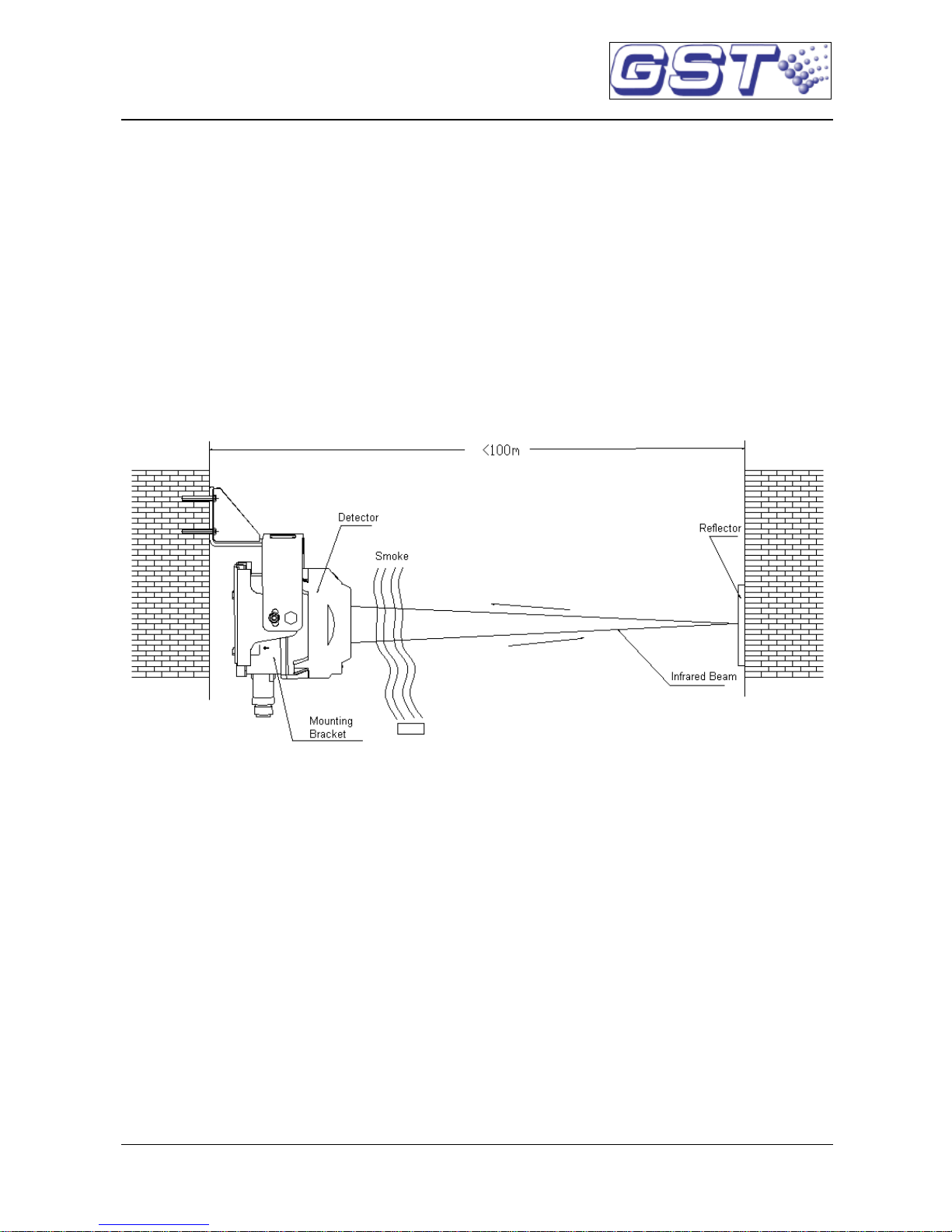
collected signals through its microprocessor. When the detector is in
normal monitoring state, the intensity of infrared beam received by the
receiver is steady at a certain level. When smoke particles enter the
detecting area, the intensity of infrared light reaching the receiver falls
owing to light scattering. When the smoke particles reach a certain
density, and the intensity of infrared light received is reduced below the
preset threshold value,the detector alarms fire and illuminates red LED.
The fire signal will be transmitted to fire alarm control panel connected
with the detector. Operation principle is shown in Fig. 2.
Fig. 2
V Mounting and Wiring
1. Ambient Conditions for Installation
The detector works on light obscuration principle, so any fixed or
moving obscuration in its optical pathway must be avoided when
locating it.
The wall for mounting either the detector or the reflector should be firm
and smooth. The detector is mounted vertical to the wall. The wall may
seem to be smooth, but corrugated or uneven, or may be changed by
the environment (in rainy season or in winter) and the installer should
Page 8

D-9105RExd
Digital Flame Proof Reflective Beam Detector
Installation and Operation Manual The Intelligent Solution
6
ensure the detector not affected by these factors. If the detector is
installed on sustaining rack similar to metal tube, make sure the
sustaining rack is installed firmly.
Not Fit For Locations where:
The heightof the roof is over 40m.
There is no roof at all.
The space is lower than 1.5m.
There are a lot of dust, powder or vapor.
It is clean normally, but can be dusty in some special cases.
Temperature is high. Note: Temperature at top part of a
workshop with transparent roof may be over 50℃ when
there is sunshine.
There is no access for maintenance.
The Mounting wall or fitting is greatly affected by mechanical
vibration.
There are fixed or moving objects within 1m from the
detector’s optical pathway.
There is strong magnetic field.
2. Mounting Height and Position
The mounting height of the detector and reflector should be most
accessible by smoke into beam zone. The following recommendations
are for reference:
(1) When space height is not over 5m, the detector and reflector should
be mounted on the two facing walls 0.5m from the ceiling, as shown
in Fig. 3.
Page 9

D-9105RExd
Digital Flame Proof Reflective Beam Detector
Installation and Operation Manual The Intelligent Solution
7
Reflector
Detector
4.5m
5m
Fig. 3
(2) When space height is between 5m and 8m, the detector and
reflectorshould be mounted on the two facing walls 0.5m to 1m from
the ceiling, as shown in Fig. 4.
Reflector
Detector
7m
6m
Fig. 4
(3) When space height is more than 8m, the roof is normally gabled
without ceiling, the detector and reflector should be mounted on the
two facing walls about 8m from the floor, ensuring that the vertical
Page 10

D-9105RExd
Digital Flame Proof Reflective Beam Detector
Installation and Operation Manual The Intelligent Solution
8
distancebetween the detector/reflectorand top of the building is not
less than 0.5m, as shown in Fig. 5.
Reflector
Reflector
Detector
Detector
12m
8m
Fig. 5
(4) For gable structure with space height about 8m, the detector and
reflector should be mounted on the two facing walls 1.5m from the
gabled girder,as shown in Fig. 6.
Detector
Detector Detector
Reflector Reflector
Reflector
6.5m
8m
Fig. 6
(5) If the surroundings are glass or transparent plastic, please place the
detector on the south wall in a building. If the detector cannot be
Page 11

D-9105RExd
Digital Flame Proof Reflective Beam Detector
Installation and Operation Manual The Intelligent Solution
9
mounted northward, then place the detector on the west wall. For
applications where sunlight can reach the detector after reflected,
please consider mounting a sunshade over the detector’s optical
pathway or contact our field application engineer for a solution.
3. Mounting
(1) Setting Length of Optical Pathway
Before installation, you need to set the length of optical pathway
first by setting device typeof the detector. The detector can work at
two length ranges. When mounting distance between the detector
and the reflector is not lessthan40m (but not more than100m),the
detector type should be set at “52”(factory default). When the
mounting distance between the detector and the reflector is less
than 40m (but more than 8m), the detector type should be set at
“51”. Refer to Section VII Operation for detailed setting methods.
(2) Mounting the detector
Align the detector and the reflector horizontally on the two facing
walls of the monitoring area, as shown in Fig. 2.
The detector is wall-mounted. First mount the adjustment frame
on the wall, then hang the detector on it, and finally secure them to
the wall. The steps are as follows:
a. Installing the adjustment frame
Secure the adjustment frame on the wall using an M6 expansion
bolt, as shown in Fig. 7.
Page 12

D-9105RExd
Digital Flame Proof Reflective Beam Detector
Installation and Operation Manual The Intelligent Solution
10
Fig. 7
b. Installing and adjusting the detector
Hang the detector with the lining board onto the adjusting frame
and secure them using M5 screw (Fig. 8).
Fig. 8
c. Installing the reflector
The reflector is mounted opposite the detector but in line with it.
When the distance between the detector and the reflector is more
Page 13

D-9105RExd
Digital Flame Proof Reflective Beam Detector
Installation and Operation Manual The Intelligent Solution
11
than 8m(less thanor equalto 40m), one reflectoris enough. When
the distance is more than 40m (less than or equal to 100m), four
reflectors are needed. Two 6 plastic expansion bolts are needed
to fix a single reflector. Mounting size is shown in Fig.9a. If four
reflectors are needed, place them seamlessly as shown in Fig. 9b.
Fig. 9a Fig. 9b (Not to Scale)
4. Wiring
(1) It is recommended to use multi-core copper cable with core cross
section≥1.0mm2, and external diameter 8mm~10mm in Zone 1
and 2. The cable shall meet field requirements on resistance to
heat, corrosion and fire. If there’s no special requirement, 10
screenedcable can be used. Connectthe screenlayer to the safety
earth position inside the housing. Cable layout shall also meet
requirement in explosive environment. It’s prohibited for the cable
to have jointsin explosiveenvironment.If a joint is necessary under
special condition, it’s only allowed in Zone 2 with the joint protected
with explosion-proof junction box.
(2) Connect 24VDC power cable (without polarity) to terminal D1 and
D2 of the detector. K11, K12 are volt-free fire output contacts. K21
and K22 are volt-free fault output contacts. No cable connection is
necessaryfor the reflectors. Terminals are shown in Fig. 12. Z1 and
Z2 are for polarity-insensitive connection with FACP loop. Refer to
Page 14

D-9105RExd
Digital Flame Proof Reflective Beam Detector
Installation and Operation Manual The Intelligent Solution
12
Fig. 10 for terminals.
K11K12K22 K21 D2 D1 Z2 Z1
Fig. 10
If the detector does not connected with GST fire alarm control panel,
D1 and D2 are to be connected with 24VDC power cable
polarity-insensitively, K11 and K12 are used as volt-free fire alarm
output contact, and K21 and K22 volt-free fault output contact, as in Fig.
11.
Fig. 11
(3) Connect the earth cable to the earth point on the housing.
(4) Connect the ribbon cable of the detector body to XT4 on the
interface board on the base, and then install the detector body onto
the base. Make sure the location element on the base in align with
the U-shaped groove on the detector body.
(5) Secure the body with the base with the 4Allen screws.
(6) After installation, double-check the following: If there is cracks or
holes on the surface of the housing; if the base and detector body
Wiring hole for
24VDC Power supply
Wiring hole for
contact signal
Page 15

D-9105RExd
Digital Flame Proof Reflective Beam Detector
Installation and Operation Manual The Intelligent Solution
13
are securely installed; if there is scratches or cracks in the glass
detector window; if there is sealing ring at the wiring hole; if the
sealing ring matches the cable gauge; if the locking nut at the
wiring hole is locked; if there is earth cable at earth mark position.
Note:
(1) If the detector connects with GST fire alarm control panel, only one
wiring hole is needed. The other one should be stopped with an
end cap, as shown in Fig. 1.
(2) If the detector does not connected with GST fire alarm control
panel, the two wiring holes are both needed, as shown in Fig. 11.
VI Commission
1. Steps
a) Take off the protective membrane carefully on the surface of the
reflector and the detector. Do not scratch or contaminate their
surfaces.
b) Power up the control panel and detector. Put the commission area
of the commission tool close to the part of detector with a mark
○
M .There may be two cases with the LEDs:
(1) Green LED flashes.
(2) Green LED illuminates continuously.
Then take away the commission tool.
c) If green LED flashes, it means the received light is quite weak (the
slower the flashing frequency, the weaker the received light signal
is). Tune the adjusting wheel and rotary rack on the detector to align
the light beam until green LED is lit continuously, showing that the
light received by the detector is strong. Then stop regulating and
enter step d).
If green LED illuminates continuously, it means the received light is
Page 16

D-9105RExd
Digital Flame Proof Reflective Beam Detector
Installation and Operation Manual The Intelligent Solution
14
quite strong, you can go straight to step d).
Note: Observe the detector’s optical pathway carefully to ensure
that the received light signal is reflected by the reflector rather
than by obscurations like wall, ceiling, or pillar. If uncertain, verify
by covering the reflector with opaque objects. If the green LED
flashes, it means the light is from the reflector. If the green LED
constantly lights, then the light is not from the reflector. The
optical pathway should be adjusted again.
d) Gently tighten the screws at the top middle and on the two sides of
the adjusting frame.
e) Put the magnet of commission tool close to the area marked with
○
M until yellow LED illuminates constantly, then remove the
commission tool quickly and make sure there is no obscuration on
the optical pathway. About 5 seconds later, the detector begins to
adjust automatically. Yellow LED flashing means weak light, green
LED flashing means strong light. If red LED, yellow LED and green
LED flash alternately, this means the detector failed to adjust
automatically and cannot enter normal monitoring state. Please
open the detector’s top cover and do adjustment from step b). If
yellowLED and green LED illuminate no more, and red LED flashes
periodically, this means the detector is at the best position and has
entered normal monitoring state. The commission is finished.
2. Fire alarm test
After the detector has been in normal monitoring state for 20 seconds,
cover the receiving window and transmitting window with the IR Light
Filter (please use the part for fire alarm test), the detector should report
fire alarm in 30 seconds and red LED should turn on. Remove the filter
and clear the fire alarm from the FACP,the red LED should go out, and
the detector should resume normal standby state.
Page 17

D-9105RExd
Digital Flame Proof Reflective Beam Detector
Installation and Operation Manual The Intelligent Solution
15
3. Fault test
Cover the receiving or transmitting window of the detector quickly with
the IR Light Filter to obscure the optical pathway. Yellow LED of the
detector should be turned on. Taking off the filter immediately, yellow
LED of the detector should be turned off.
4. Defect Detectors
For detectors failing in testing, please repair them following the
instructions in the sections of Troubleshooting and Maintenance, and
re-test them. If they fail again, return them to factory for repair.
VII Operation
The detector address, device type and sensitivity level can be simply
programmed by P-9910B hand held programmer. Open the detector’s
top cover, connect the ribbon cable from the detector body to XT2 of
the small connector board coming with the detector, and then connect
the I2C cable of hand held programmer (PS/2 cable) with XT1 of the
connector board (or directly connect the ribbon cable of the detector
body with the connector on the base, and the I2C cable to XT3 of the
interface board). Turn on the power of hand held programmer, input 2,
5, 9 and Function to enter I2C programming mode, the screen shows a
“0”. After programming, input 2, 5, 9 and Function again to exit I2C
programming mode and return to power-on state.
1. Reading Information
Using the hand held programmer, you can easily get original
information of the detector, such as the address. Refer to details
below:
(1) Enter I2C programming mode, the screen shows a “0”.
(2) Press Test, the screen shows the address code of the detector.
(3) Press Up, the screen shows sensitivity level and device type in
sequence.
(4) Press Down, the screen shows above contents in opposite way
Page 18

D-9105RExd
Digital Flame Proof Reflective Beam Detector
Installation and Operation Manual The Intelligent Solution
16
2. Setting Address Code
The detector offers address code programming for field application.
Refer to operation below:
(1) Enter I2C programming code, and the screen is a “0”.
(2) Input address code for programming (1~242).
(3) Press Program to start programming. “P”will be shown when
successful, otherwise an “E”will be shown.
(4) If programming is successful, press Clear, the screen will show a
“0”, and you can go on with further operations.
(5) If programming fails, pressClear, the screen will show a “0”, input
address code once again.
3. Setting Sensitivity Level
The hand held programmer can set two sensitivity levels to the
detector. 2 is sensitivity one, and 3 is sensitivity two, as detailed
below:
(1) Enter I2C programming mode of hand held programmer, and the
screen shows a “0”.
(2) Input unlock password, press Clear,and open the lock.
(3) Press Function then the figure “3”, the screen shows a “-”.
(4) Input sensitivity level to be set, and press Program to begin
programming. The screen will show a “P”if programming is
successful, otherwise it will show an “E”.
(5) Clear pressed, the screen shows “0”, and you can go on with
further operations.
4. Setting the Device Type
You can also set the device type of the detector through a programmer,
as detailed below:
(1) Enter I2C mode of the programmer, and the screen shows
“0”.
(2) Input unlock password, press Clear, and open the lock.
Page 19

D-9105RExd
Digital Flame Proof Reflective Beam Detector
Installation and Operation Manual The Intelligent Solution
17
(3) Press Function and then figure “4”, the screen shows “-”.
(4) Input the device type to be set, press Program to begin
programming. “P”will be shown when successful, otherwise “E”
will be shown.
(5) Pressing Clear shows “0”on the screen, and you can go on with
further operations.
5. Other Functions
(1) Automatic Compensation of Light
When dust exists in the working environment of the detector, the
transmitting window, receiving window and reflector may be covered
with dust, which will affect normal operation. In order to solve the
problem, the detector is designed withautomaticcompensation of light.
When there is dust on windows, the detector can judge the amount of
dust, and compensate the received signal through internal program
and circuit to ensure the detector can continue working normally. The
detector gives fault signal when dust on the lens and reflector surface
reaches a certain level and light compensation reaches the limit for the
detector to work normally.
(2) Self-diagnosis on Optical Signal
The detector has functions of checking transmitting, receiving and
amplifying circuit. When there is fault with these three parts of circuit
during operation, the detector will generate fault information.
VIII Troubleshooting
If the detector reportsfault after long time running,please first check
if it’s damaged. Make sure it’s securely installed on the wall or other
fixed supporters. Then check the dust accumulation level and
position deviation to see if these has resulted in fault in automatic
compensation, and then consider other types of fault.
If the surface of the transmitting/receiving window or the reflector is
Page 20

D-9105RExd
Digital Flame Proof Reflective Beam Detector
Installation and Operation Manual The Intelligent Solution
18
found to be contaminated,please clean it with soft clothand alcohol.
Avoid scratching the surface. Do not clean the surface using water
or other chemicals. After cleaning, please commission the detector
again to make it work in normal standby state.
Common problems and repair methods are as shown in Table 1.
Table 1
Problems Reasons Repair Methods
Working LEDs
not lit after
power up.
a) 24V power off
b) Working LEDs damaged.
c) Transient suppressor VD12 damaged.
d) DiodeVD1, VD2, VD10, VD11
breakdown resulting in short circuit
with ground.
e) N1, N2 damaged.
f) The flexible cable inside was not
connected, or not connected correctly.
If the problems are
mentioned in a) ~ e) ,
replace the component
with problem.
If in f) connect again in
right way.
Fault LED
constantly
illuminates
after power up
a) Device type
read by programmer is
not 51 or 52.
b) The optical pathway is not well
aligned.
a) Correct the device type.
b) Commission the
detector again. If
commissioning fails for
3 time, please return the
detector for repair.
Reports loop
fault after
power-up
a) Diode VZ1, VZ2, VD3 or VD4 is
broken, and is shorted to earth.
b) TVS diode VC13 is damaged.
Commission once more.
FACP reports
detector fault
after
registration.
The detector does not enter normal
operation state.
Re-commission the
detector.
The FACP
does not
register the
detector after
power-up
a) Loose connection with FACPloop.
b) 24V power is not applied.
c) N3 or N4 is damaged.
d) The flexible cable inside the detector
is not connected or not connected
well.
e) N1 or N2 is damaged.
Replace the faulty
component, re-connect the
flexible cable or re-register
the detector.
Green LED
flashes after
power-up
despite
adjustment
a) Transmitting diode or circuit is
damaged.
b) Receiving diode or amplifying circuit
is damaged.
Replace the faulty
component.
Page 21

D-9105RExd
Digital Flame Proof Reflective Beam Detector
Installation and Operation Manual The Intelligent Solution
19
Reports fault
after a period
of normal
operation
The detector cannot work normally. Commission once more
Reports fire
after operation
for some time,
and reports
fault after
restarted
The detector has deviated due to
external vibration.
Commission once more
Fire signal
cannot be
cleared
a) There is obscuration on the optical
pathway between the detector and
the reflector.
b) The angle of optical pathway has
changed and need to be aligned
again.
c) The transmitting diode or circuit
damaged.
d) The photodiode or amplifying circuit
damaged.
For a) andb), commission
once again.
For c) and d), replace the
faulty component.
The control
panel can’t
receive
fire or fault
signals.
No registration. Register again.
IX Maintenance
The detector is fire protection product, operation of which must be
well recorded by the personnel on duty and shift.
Personnel on duty should be familiar with the functions and
operation process of the device to avoid mis-operation.
Test alarm function once every 6 months.
X Caution
Protect the detectorfrom damage in maintenance.
Install and maintain the detector in strict compliance with safety
regulations for explosive and hazardous areas.
Never open the housing with power on.
The detector housing should be earthed.
Page 22

D-9105RExd
Digital Flame Proof Reflective Beam Detector
Installation and Operation Manual The Intelligent Solution
20
Power up only after all devices are connected.
Commissionthe detector after installation and maintenance.
During commissioning, the FACP may report detector fault which
does not affect commissioning.
The detectorbase should be fixed directlyon solid wall or frame that
will not be deformed by vibration. Any deformable material such as
paperboard, plastic board, foam board or thin wood board should
not be placed between the base and the wall or the bracket.
XI Accessories
Accessories provided with the detector are as follows:
FourM6 x 60 expansion bolts.
Four M5 cross recessed pan head screws.
One adjustment bracket.
One IR Light Filter.
One Commission Tool.
OneAllen key M8.
One connector board.
Page 23

GST China
Gulf Security Technology Co., Ltd.
No. 80, Changjiang East Road, QETDZ, Qinhuangdao, Hebei,
P. R. China 066004
Tel: +86 (0) 335 8502528
Fax: +86 (0) 335 8508942
Email: sales@gst.com.cn
www.gst.com.cn
GST UK
Global System Technology PLC
Lion Court, Staunton Harold Hall, Melbourne Road, Ashby de la Zouch,
Leicestershire, England LE65 1RT
Tel: +44 1283 225 478
Fax: +44 1283 220 690
Email: info@gst.uk.com
www.gst.uk.com
GST Dubai
Global System Technology PLC
PO Box 17998 Unit ZA04 JEBELALI Free Zone,
Dubai, UAE
Tel: +971 (0) 4 8833050
Fax: +971 (0) 4 8833053
Email: info@gst.uk.com
www.gst.uk.com
 Loading...