

Page 1
The Intelligent Solution
Features
High bright red LEDs are used as light source.
High sound level.
Circuitry and base are twisted together.
Standard: EN 54-3.
Description
C-9404(Ex) Explosion Proof Conventional
Sounder and C-9403(Ex) Explosion Proof
Conventional Sounder Strobe (hereinafter called the
sounder/sounder strobe) is a kind of audible/audible
and visual alarm device used to warn people in field
when fire occurs. It’s applicable to zone 1 and zone 2
of areas with explosion-proof requirement in
petroleum and chemical industries. It can match with
I-9333 Interface.
Both shallow base with 25.5mm high and deep base
with 40mm high are available, it employs deep base
if there is no special statement in this manual.
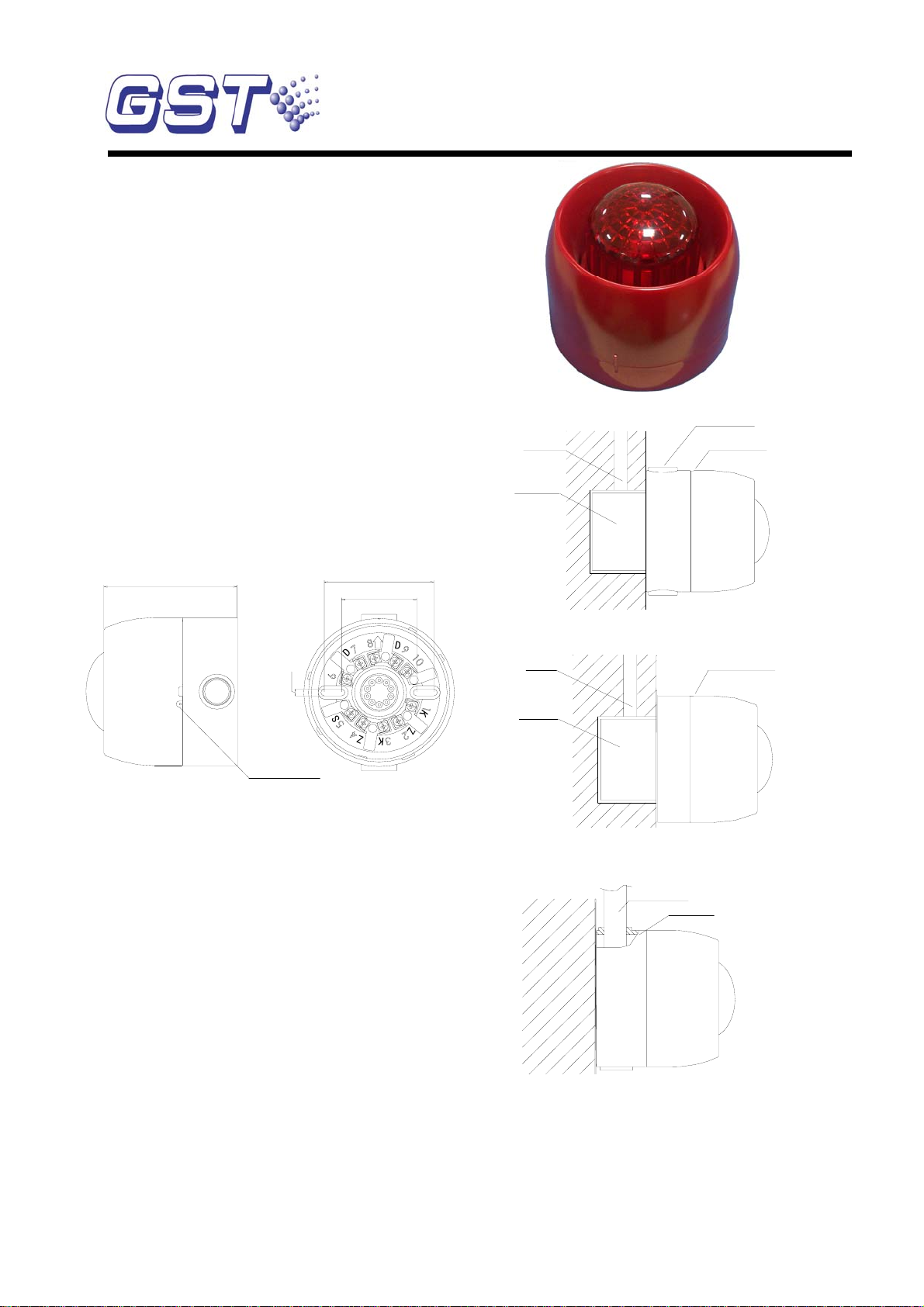
Explosion Proof Conventional Sounder Strobe
C-9404(Ex)
Explosion Proof Conventional Sounder
C-9403(Ex)
Knock-off Hole
Conduit
Electrical Box
sounder/Sounder Strobe
Connection & Wiring
Terminals on the base are shown in Fig. 2.
97.5mm
5mm
Arch knock off Hole
80mm
55mm
D
2
S
D
1
G
1
K
Z
2
Z
1
2
K
Fig. 1 Fig. 2
D1+(9), D2- (7): Connected with I-9333
Interface, polarized. D1 is connected with (3) of the
safety barrier and D2 to (4).
Recommended Wiring
Intrinsically safe cable with cross section not less
than 1.5mm2, subject to local codes.。
Installation
When the sounder/sounder strobe is surface
mounted, it should be placed 0.2m from the ceiling
for normal space height. When conduit is embedded,
the base can be mounted on the electrical box.
When conduit is surface mounted, the deep base
should be adopted. Knock the knock-off hole, then
connect the conduit with it. The mounting hole
spacing and mounting direction are shown in Fig. 2.
Mounting method is shown in Fig. 3a and Fig. 4.
When the shallow base is required, the
sounder/sounder strobe only adopts conduit
embedded. Its mounting method is shown in Fig. 3b.
Fig. 3a
Conduit
Electrical Box
sounder/Sounder Strobe
Fig. 3b (shallow base)
Conduit
sounder/Sounder Strobe
Fig. 4
The base and the sounder/sounder strobe are
twisted together. When mounting, remove the
sounder strobe, thread cables through the cable
entry in the base and connect with corresponding
terminals, then twist the sounder/sounder strobe
onto the base.
30302556 Issue 2.03
Page 2
If the sounder/sounder strobe is required
anti-removal, knock down the arch knock-off hole as
shown in Fig. 1 and fix it with ST2.9×6.5 tapping
screws (in this case, it must be removed by a special
tool).
Application
Specification
Power Loop
voltage when
activating
Power Loop
voltage in standby
24VDC(16VDC~28VDC)
7VDC(5VDC~8VDC)
state
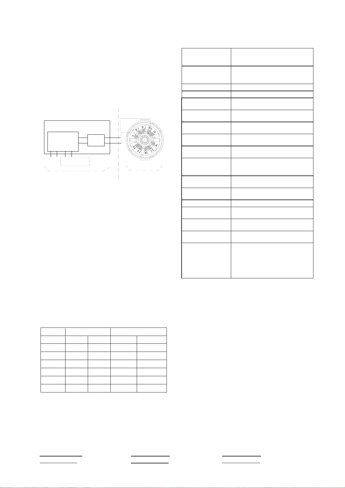
the sounder/sounder strobe can match I-9333
Interface to form an intrinsically safe system. The
system wiring is shown in Fig. 5.
Safety Area
Hazardous Area
standby current ≤5mA
active current ≤50mA
Wiring Polarized two-wire with I-9333
Interface
Sound Level See the above sound level data
table
I-9333 Interface
I-9333 Circuit
Board
D1 D2 Z1 Z2
24VDC
Fire Alarm Control Panel
1(+)
L+
NF928 Zener
2(-)
Safety Barrier
L-
3(+)
4(-)
S
D
D
1
2
G
1
K
1
2
Z
2
Z
K
Flashing
Frequency
Tone Modification
Period
Explosion-proof
marking
Security Barrier
1.4×(1±20%)Hz(C-9403(Ex))
0.7s±20%
ExibⅡCT6
U =28V,I =93mA
0 0
Parameters
Non-intrinsincally Safe Loop
Intrinsincally Safe Loop
(NF928)
Ingress Protection
IP33
Rating
Fig. 5
Cautions
1. I-9333 Interface should be installed in safety
area, the wires of "Safety Area" should be
separated from those of "Hazardous Area", and
be kept a certain distance (at least 50mm).
2. The safety barrier should be well grounded.
The screws should not be loose. Ground
resistance should not be over 1Ω. The
parameters assigned in the intrinsically safe
loop should not be over the specified value, that
is, the capacity assigned among cables should
not be over 0.02μF, the inductance assigned
not over 2mH.
Operating
-10℃~+50℃
Temperature
Relative Humidity ≤95%, non condensing
Material and Color
ABS,red(PANTONE 1795C)
of Enclosure
Dimension
(L×W×H)
Mounting Hole
ф110mm×97.5mm (deep base)
ф110mm×83mm(shallow base)
55mm~80mm
Spacing
Weight C-9404(Ex):
About 340g(deep base)About
312.2g(shallow base)
C-9403(Ex):
About 350g(deep base)About
322.2g(shallow base)
3. During maintenance, products passing the
explosion-proof test should not be replaced and
Limited Warranty
parts and structure affecting explosion-proof
functions should not be modified.
Sound Level Data (Complies to EN54-3)
Fixed tone, Maximum Volume
Angle Horizontal Vertical
18V 28V 18V 28V
15° 74.47 78.16 71.95 75.55
45° 81.85 86.44 82.03 85.36
75° 88.06 92.47 87.88 91.66
105° 88.15 91.93 89.14 92.92
GST warrants that the product will be free from
defects in design, materials and workmanship during
the warranty period. This warranty shall not apply to
any product that is found to have been improperly
installed or used in any way not in accordance with
the instructions supplied with the product. Anybody,
including the agents, distributors or employees, is
not in the position to amend the contents of this
warranty. Please contact your local distributor for
products not covered by this warranty.
135° 80.50 85.54 82.48 87.07
165°
This document is subject to change without notice. Please contact GST for more information or questions.
GST China
Gulf Security Technology Co., Ltd.
No. 80, Changjiang East Roa ,
QETDZ, Qinhuangdao, Hebe
P. R. China 066004
Tel: +86 (0) 335 8502528
Fax: +86 (0) 335 8508942
Usales@gst.com.cn
HTUwww.gst.com.cnUTH
62.32 66.37 73.93 78.07
d
i,
GST UK
Global System Technology PLC
Lion Court, Staunton Harold Hall,
Melbourne Road, Ashby de la Zouch,
Leicestershire, England LE65 1RT
Tel: +44 1283 225 478
Fax: +44 1283 220 690
HTUinfo@gst.uk.comUTH
HHTUwww.gst.uk.comUTHH
GST Dubai
Global System Technology PLC
PO Box 17998 Unit ZA04
JEBEL ALI Free Zone,
Dubai, UAE
Tel: +971 (0) 4 8833050
Fax: +971 (0) 4 8833053
HTUinfo@gst.uk.comUTH
HHTUwww.gst.uk.comUTHH
30302556 Issue 2.03
 Loading...