

Page 1
100mm
C
25mm
5mm
03mm
45mm~75mm
Mounting
Hole
Z
-
0
3
D
Conduit
Back Box
Detector
Base
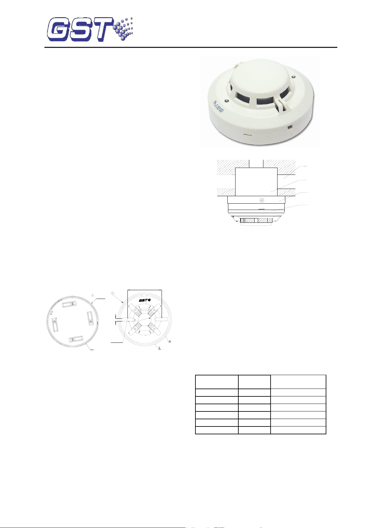
Input Number
Smoke
Sensitivity
Heat Sensitive
1
Level 1
Rate of rise
2
Level 2
Rate of rise
3
Level 3
Rate of rise
11
Level 1
Fixed temperature
12
Level 2
Fixed temperature
13
Level 3
Fixed temperature
C-9101 Conventional Combination
Heat/Photoelectric Smoke Detector
Features
Drift compensation to suit environment changing
extensively.
Integrated algorithm for analyzing fire, improving
the sensitivity highly.
Self-diagnostic.
Removable innovative sensing chamber, easy for
maintenance.
Reporting dirt fault for contaminated chamber.
Remote indicator output available.
3 levels sensitivities programmable; Level 1
complies with EN 54-7. Fix temperature or rate of
rise programmable, rate of rise mode complies
with EN 54-5.
Description
C-9101 Conventional Combination Heat/Photoelectric
Smoke Detector is consisted of smoke sensing and
semi-conductor temperature sensing parts in
processing and circuitry. Matching with P-9907 Active
End of Line Unit (AEOL), it can be connected with
conventional fire alarm control panel or intelligent fire
alarm control panels through I-9319 Addressable Zone
Monitor Unit to execute signal processing. This
non-addressable detector has the advantages of both
conventional photoelectric detector and rate of rise
and fixed temperature heat detector. Just because of
the combination technology of smoke detector and
heat detector, it overcomes the non-sensitivity to dark
smoke particles of ordinary scattering type
photoelectric detectors. It can also pick up fire with
obvious rise of temperature such as alcohol fire, thus
extending the application range.
Connection and Cabling
Fig.1 shows the detector bottom and Fig. 2 the base.
Fig. 1 Fig. 2
There are four terminals with numbers on the base.
1: Detection zone positive IN
2: Detection zone positive OUT
3: Detection zone negative IN and OUT
2: Positive terminal of remote indicator
4: Negative terminal of remote indicator
Recommended Cabling
1.0mm2 or above fire cable for all the wires, laid out
through metal conduit or flame retardant conduit,
subject to local codes.
Fig. 3 shows mounting of the detector.
Fig. 3
Applications
Warning: The alarm current depends on the
current limit of the control panel. 24VDC cannot
power the detector directly. Otherwise the detector
will be blown up for lack of current limit resistor.
Level 1 is defaulted, which can be modified by
P-9910B programmer. Please refer to P-9910B Hand
Held Programmer Installation and Operation Manual
for details.
In power-on state of the programmer, input unlocking
password and press Clear to unlock. Press Function,
then press “3”, the screen shows “-” at the last digit.
Input corresponding sensitivity or parameter and press
Program, the screen will show a “P”, the
corresponding sensitivity or parameter is programmed.
Press Clear to clear the "P". Input locking password
and press Clear to return.
Parameters set using programmer
Installation
A fixed installation direction is ensured by the location
elements on the detector and the base. Fix the base
with two tapping screws, and then align mark C on the
detector with A on the base, rotate the detector to align
mark C with mark B (Refer to Fig. 1 and 2 for the
position of the marks), the detector will be fitted to the
base.
30309172 Issue 1.01
Rate of rise and level 1 is defaulted.
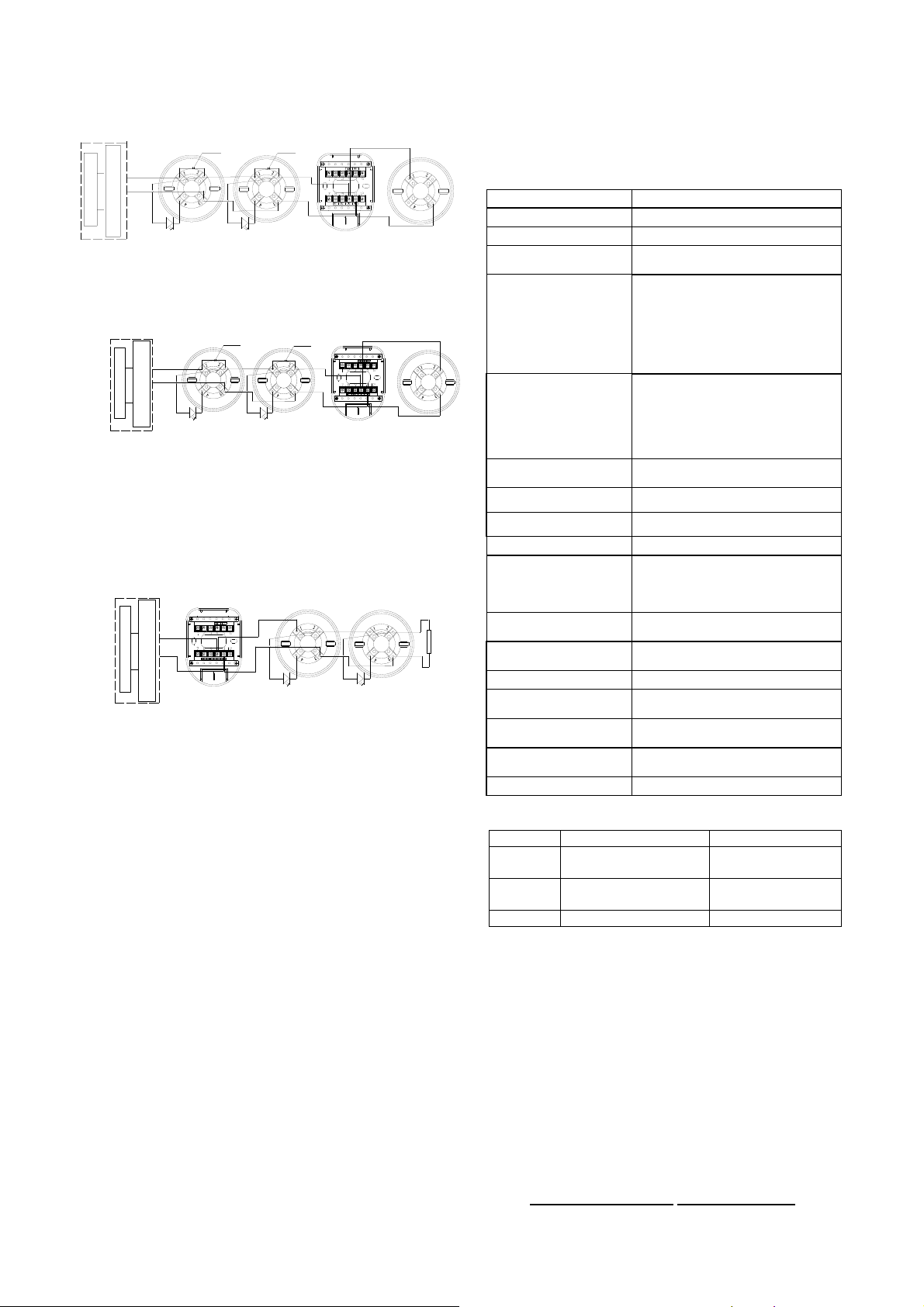
1. When the detector is connected with conventional
fire alarm control panel (those within the dotted line
are equivalent to a conventional fire alarm control
panel) or I-9319 addressable zone monitor unit in
series, if a P-9907 AEOL is connected to the end of
output loop, an 1N5819 Diode should be connected to
the detector base.
Page 2
1) Used as the detector base, the AEOL is to install a
Remote Indicator
P-9907 AEOL
-
+
Conventional MCP
-
+
Conventional Detector
Output+
Output-
Diode
Fire Alarm Control Panel
Diode
Remote Indicator
Conventional Detector
I-9319
Addressable Zone Monitor Unit
Remote Indicator
P-9907 AEOL
-
+
-
+
Conventional Detector
Output+
Output-
Diode
Fire Alarm Control Panel
Remote Indicator
Diode
Conventional Detector
Conventional MCP
I-9319
Addressable Zone Monitor Unit
Remote Indicator
-
+
Conventional Detector
-
+
Output+
Output-
4.7k
Ω Resistor
Fire Alarm Control Panel
Conventional Detector
Conventional MCP
Remote Indicator
I-9319
Addressable Zone Monitor Unit
Operating Voltage
24VDC (12VDC~28VDC)
Standby Current
≤60μ A
Alarm Current
10mA≤I≤40mA
Maximum Ripple
Voltage
2V (peak-to-peak value)
Indicator
Red: flashes in normal and
illuminates in alarm.
The LED is quiet in fault. And it
lights and then turns out about
every three seconds
periodically when reported
dirty.
Remote Indicator
Output
Directly connecting with
indicator (built-in 5.1kΩ
resistor, maximum output
current is 5.0mA). Quiet in
normal condition. Flashes in
alarm.
Alarm Clear
Instantaneous Power-off (10s
MAX., 1.5VDC MAX.)
Power-up Time
≤10s
Action Temperature
62℃
Class
A2R
Wiring
Polarized 2-core for detection
zone cable.
Polarized 2-core for remote
indicator.
Ingress Protection
Rating
IP22
Environment
Temperature
-10℃~+50℃
Relative Humidity
≤95%, non condensing
Material of
Enclosure
ABS
Dimensions
Diameter: 100mm
Height: 56mm (with base)
Mounting Hole
Distance
45mm~75mm
Weight
126g
Model
Name
Remark
P-9907
Active End of Line
Unit
Order separately
P-9910B
Hand Held
Programmer
Order separately
DZ-03
Base
Order separately
This document is subject to change without notice. Please contact GST for more information or questions.
Gulf Security Technology Co., Ltd.
No. 80, Changjiang East Road, QETDZ, Qinhuangdao, Hebei, P. R. China 066004
Tel: +86 (0) 335 8502528 Fax: +86 (0) 335 8508942 gst.info@fs.utc.com www.gst.com.cn
conventional detector on it. The system
connection is shown in Fig. 4.
Fig. 4
2) When the AEOL is not used as the detector base,
a cover should be added, the system connection
is shown in Fig. 5.
Fig. 5
2. When the detector is connected with conventional
fire alarm control panel (those within the dotted line
are equivalent to a conventional fire alarm control
panel) or I-9319 Addressable zone monitor unit in
series, if an end of line resistor is connected to the end
of output loop, then no diode is connected to the
detector base. The system connection is shown in
Fig. 6.
After cleaning, install the detector again, and test
after re-installing. Notify the proper authorities
when the system is back in service.
Fire simulation test should be made to the
detector once half a year.
Specification
Fig. 6
Maximum 15 detectors can be connected in one zone.
Cooperating with end of line device, the compatible
panel can monitor the cable for open circuit and short
circuit. Panel will report if any detector is removed.
With the AEOL, the functioning of other device will not
be affected by the detector removal.
Accessories and Tools
Maintenance
The detector should be installed just before
commissioning and kept well before installation,
taken corresponding measures for dust-proof,
damp-proof and corrosion-proof.
The dust cover cannot be removed until the
project has been plunged into usage, otherwise it
cannot alarm normally.
The detector should be cleaned at least once a
year to ensure normal operation of the system.
If nuisance alarms are often found of the detector
on site, the sensing chamber should be cleaned
and replaced when necessary.
Before cleaning, notify the proper authorities that
the system is undergoing maintenance and will
temporarily be out of service. Disable the zone or
system undergoing maintenance to avoid
unwanted alarms.
30309172 Issue 1.01
Limited Warranty
GST warrants that the product will be free of charge
for repairing or removing from defects in design,
materials and workmanship during the warranty period.
This warranty doesn’t cover any product that is found
to have been improperly installed or used in any way
not in accordance with the instructions supplied with
the product. Anybody, including the agents,
distributors or employees, is not in the position to
amend the contents of this warranty. Please contact
your local distributor for products not covered by this
warranty.
 Loading...