

GSSI SIR 4000 User Manual


Copyright© 2014-2016 Geophysical Survey Systems, Inc.
All rights reserved
including the right of reproduction
in whole or in part in any form
Published by Geophysical Survey Systems, Inc.
40 Simon Street
Nashua, NH 03060-3075 USA
Printed in the United States
SIR, RADAN and UtilityScan are registered trademarks of Geophysical Survey Systems, Inc.

Geophysical Survey Systems, Inc. SIR® System 4000
Manual
Limited Warranty, Limitations of Liability and Restrictions
Geophysical Survey Systems, Inc. hereinafter referred to as GSSI, warrants that for a period of
24 months from the delivery date to the original purchaser this product will be free from defects in
materials and workmanship. EXCEPT FOR THE FOREGOING LIMITED WARRANTY, GSSI
DISCLAIMS ALL WARRANTIES, EXPRESS OR IMPLIED, INCLUDING ANY WARRANTY OF
MERCHANTABILITY OR FITNESS FOR A PARTICULAR PURPOSE. GSSI's obligation is limited to
repairing or replacing parts or equipment which are returned to GSSI, transportation and insurance prepaid, without alteration or further damage, and which in GSSI's judgment, were defective or became
defective during normal use.
GSSI ASSUMES NO LIABILITY FOR ANY DIRECT, INDIRECT, SPECIAL, INCIDENTAL OR
CONSEQUENTIAL DAMAGES OR INJURIES CAUSED BY PROPER OR IMPROPER OPERATION
OF ITS EQUIPMENT, WHETHER OR NOT DEFECTIVE.
Before returning any equipment to GSSI, a Return Material Authorization (RMA) number must be
obtained. Please call the GSSI Custom er Service Manager who will assign an RMA number. Be sure to
have the serial number of the unit available.
FCC Class B Compliance
This device complies with Part 15 of the FCC Rules. Operation is subject to the following two
conditions: (1) the device may not cause harmful interference, and (2) this device must accept any
interference received including interference that may cause undesired operation.
This Class B digital apparatus complies with Canadian ICES-003
Contains FCC ID: VRA-SG9011089E
Warning: Changes or modifications to this unit not expressly approved by the party responsible for
compliance could void the user’s authority to operate the equipment.
Note: This equipment has been tested and found to comply with the limits for a Class B digital device,
pursuant to Part 15 of the FCC Rules. These limits are designed to provide reasonable protection against
harmful interference when the equipment is operated in a commercial environment or residential
installation. This equipment generates, uses, and can radiate radio frequency energy and, if not installed
and used in accordance with the introduction manual, may cause harmful interference to radio
communications. However, there is no guarantee that interference will not occur in a particular
installation.
Shielded cables must be used with this unit to ensure compliance with the Class B FCC limits.
Canadian Emissions Requirements
This Class B digital apparatus complies with Canadian ICES-003.
Cet appareil numerique de la classe B est conforme a la norme NMB-003 du Canada.
Notice
Operation is subject to the following two conditions: (1) this device may not cause interference, and (2)
this device must accept any interference, including interference that may cause undesired operation of the
device.


Geophysical Survey Systems, Inc. SIR® 4000
Manual
Table Of Contents
Chapter 1: Introduction ................................................................................................................1
1.1: Unpacking Your System ............................................................................................. 1
1.2: General Description ..................................................................................................... 1
1.3 Cautions and Warnings ............................................................................................... 7
Chapter 2: Getting Started and Expert Mode Setup ..........................................................9
2.1: Hardware Setup ............................................................................................................ 9
2.2: Introduction Screen .................................................................................................. 11
2.3: Setup Collect/Playback Screen ............................................................................. 18
2.4: The Toolbar .................................................................................................................. 42
Chapter 3: Setting Up Your SIR 4000 for 2D Data Collection and Playback in
Expert Mode ................................................................................................................................... 63
3.1: Setting Up Distance Mode Data Collection ...................................................... 63
3.2: Setup for Single Line 3D Collection in Expert Mode ...................................... 67
3.3: Setting Up for Time Mode Data Collection ....................................................... 68
3.4: Setting Up for Point Mode Data Collection ...................................................... 71
3.5: Playing Back Collected Data .................................................................................. 74
3.6: Saving an Image ......................................................................................................... 74
Chapter 4: Using Quick3D Mode ............................................................................................ 77
4.1: Quick3D File Structure ............................................................................................. 77
4.2: Setting Up a Physical 3D Grid ................................................................................ 78
4.3: Setting Up Quick3D Collection ............................................................................. 79
4.4: Step By Step Quick3D Setup .................................................................................. 80
4.5: Collecting 3D Data .................................................................................................... 83
4.6 Modify the 3D Display during Collection ........................................................... 87
4.7 GPS Enabled 3D Collection ..................................................................................... 89
4.8 Quick3D Playback ....................................................................................................... 90
Chapter 5: Summary of Pre-Set Mode Parameters .......................................................... 95
5.1: StructureScan2D ........................................................................................................ 95
5.2: StructureScan3D ...................................................................................................... 103
Chapter 6: Data Transfer and File Maintenance .............................................................115
6.1: Transfer to a PC via a USB Memory Stick ......................................................... 115
6.2: Deleting Data from the System .......................................................................... 115
Chapter 7: Using a GPS with your SIR 4000 ......................................................................117
7.1: Connecting a GPS .................................................................................................... 117
7.2: Understanding GPS................................................................................................. 118
7.3 What is the DZG File? .............................................................................................. 119
7.4 What is WAAS? ........................................................................................................... 121
7.5 What is NMEA? ........................................................................................................... 121
MN72-574 Rev D

Geophysical Survey Systems, Inc. SIR® 4000
Manual
Appendix A: SIR 4000 System Specifications ...................................................................123
A.1: System Hardware .................................................................................................... 123
A.2: Data Acquisition and Software ........................................................................... 124
A.3: System Includes ....................................................................................................... 124
Appendix B: The How-To’s of Field Survey .......................................................................125
B.1: Site Selection ............................................................................................................ 129
B.2: Targets......................................................................................................................... 130
B.3: Data Collection Methods: 2D vs. 3D .................................................................. 132
Appendix C: Dielectric Values For Common Materials ...............................................135
Appendix D: Listing of Antenna Parameters ...................................................................137
D.1: Preloaded Setups in Expert Mode ..................................................................... 137
D.2: Parameter Listing for Older/Specialty Antennae ......................................... 140
Appendix E: Glossary of Terms and Suggestions for Further Reading...................143
MN72-574 Rev D

Geophysical Survey Systems, Inc. SIR® 4000
Manual
Chapter 1: Introduction
This manual is designed for both the novice and experienced user of ground penetrating radar. It is
intended as both a reference and a teaching tool and it is recommended that you read the entire manual,
regardless of your level of GPR experience. For information about GPR theory, please see the list of
general geophysics references that can be found in Appendix F.
If you experience operation problems with your system, GSSI Technical Support can be reached
Monday-Friday, 8:30 am - 5 pm EST, at 1-800-524-3011, or at (603) 893-1109 (International).
1.1: Unpacking Your System
Thank you for purchasing a GSSI SIR® 4000 (hereafter referred to as SIR 4000). A packing list is
included with your shipment that identifies all of the items included in your order. You should check your
shipment against the packing list upon receipt of your shipment. If you find an item is missing or was
damaged during the shipment, please call or fax your sales representative to immediately report the
problem.
Your SIR 4000 system contains the fo llowing items:
1- Digital Control Unit (DC-4000) with preloaded operating system.
1 - Transit Case
2 - Batteries
1 - Charger
1 - Sunshade
1 - Operation Manual
1 - GSSI Manual CD
1 - USB Drive
1 - Universal Mounting Bra ck et
Your choice of antenna, cables, and post-processing software is available for an additional purchase.
1.2: General Description
The SIR 4000 is a lightweight, portable, ground penetrating radar system that is ideal for a wide variety of
applications and designed to operate GSSI single digital antennas, single analog antennas, or dual
frequency antennas. The system will not support operating both a digital and analog antenna at the same
time. The various components of the SIR 4000 are described below.
The major features of the control unit are the keypad, control knob, 10.4 inch LED display with 1024 by
768 pixel resolution, connector panels (HDMI Video Out, USB 2.0, Ethernet, Serial Port I/O, digital and
analog antenna connectors, power, GPIO Connector, micro-USB), battery slot, and indicator lights. The
display screen allows you to view data in real time or in playback mode. It is readable in bright sunlight,
although a sunshade for the unit is available. Prolonged exposure to direct sunlight will cause the screen
to heat up and may affect screen visibility.
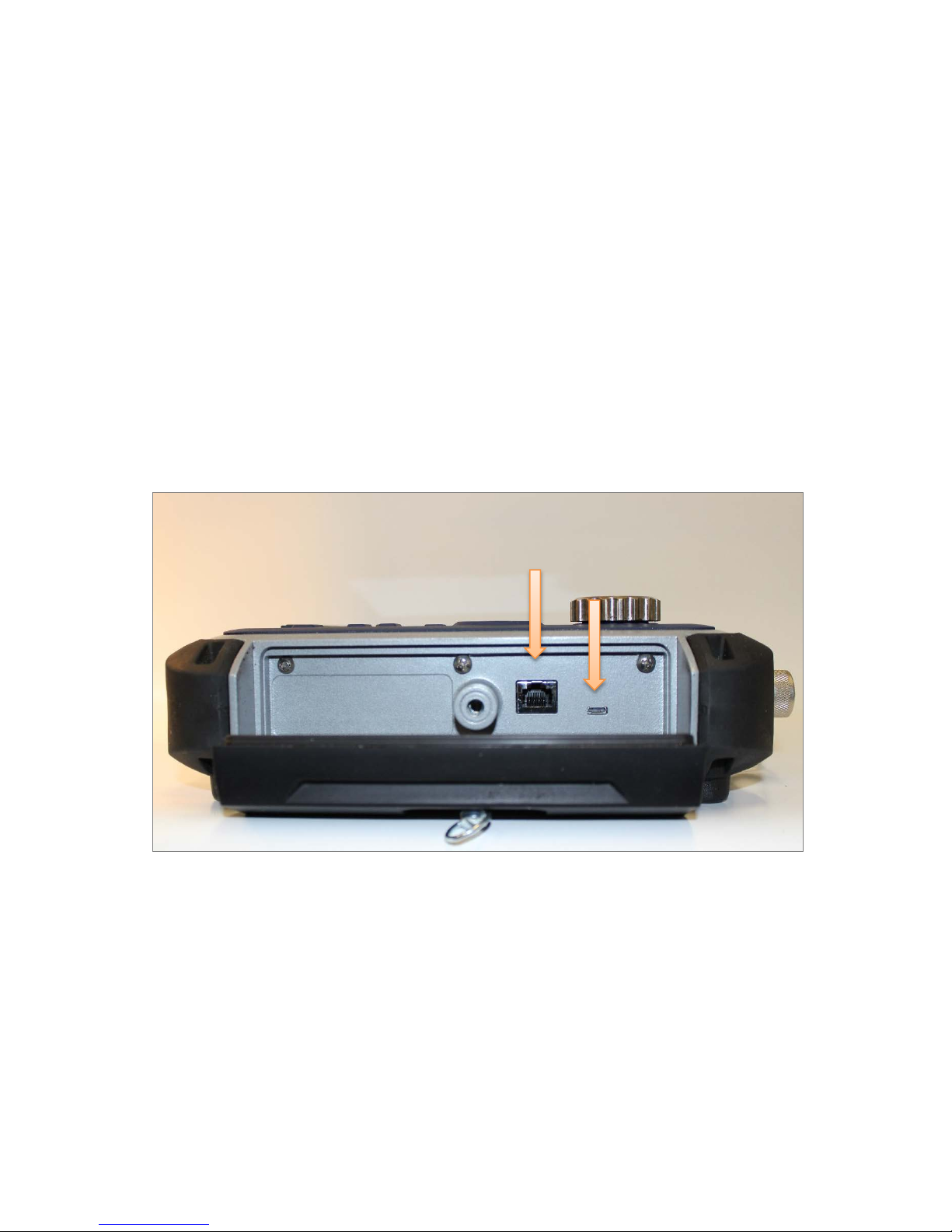
There are two latching panels on the sides of the unit that contain the battery slot, Micro-USB port, and
Ethernet port. To open the panels, rotate the locking pin until it is lo o se . To close the panel press it firmly,
push the locking pin in, and rotate the pin until it tightens. See the figure below for further detail.
MN72-433 Rev D 1

Geophysical Survey Systems, Inc. SIR® 4000
Note: It is always recommended to
when storing or transporting the SIR 4000.
Manual
Left: Side panel when closed and locked. Right: Side panel when closed and unlocked.
The battery slot on the left side of the unit accepts the 10.8 V Lithium-Ion rechargeable battery provided.
Survey time with a fully charged battery is approximately two and a half (2.5) hours. Batteries are
recharged with the included battery charger or by simply leaving the battery in the unit and connecting the
unit to a standard AC source using the optional AC adapter. Time to recharge a battery is approximately
one and half to two (1.5-2) hours. Be sure to keep
the right and left side panel covers on the unit
closed and secured while in use to ensure that no
dust or dirt enters the unit’s interior.
remove the battery from the battery slot
Compatibility
The SIR 4000 is not compatible with the following GSSI software or systems.
StructureScan Optical: When using either the black pad or the optical reader.
RADAN 5 or 6: Data collected with a SIR 4000 is also not compatible with RADAN 5 or 6. You will
need RADAN 7 or later version in order to view and process data collected with this system.
Orange Control Cables: The SIR 4000 will not work with the short, orange attenuated control cable
that was sold with the SIR 2000. The SIR 4000 will only work with non-attenuated cables (blue or black
in color). Repeated use of the orange attenuate d cab le w ith the SIR4000 may cause damage to the
SIR4000 circuitry.
MN72-433 Rev D 2

Geophysical Survey Systems, Inc. SIR® 4000
Digital
Analog
Antenna
External
Power
GPIO
HDMI
USB
2.0
Serial
Port
Manual
Hardware Connections - Top
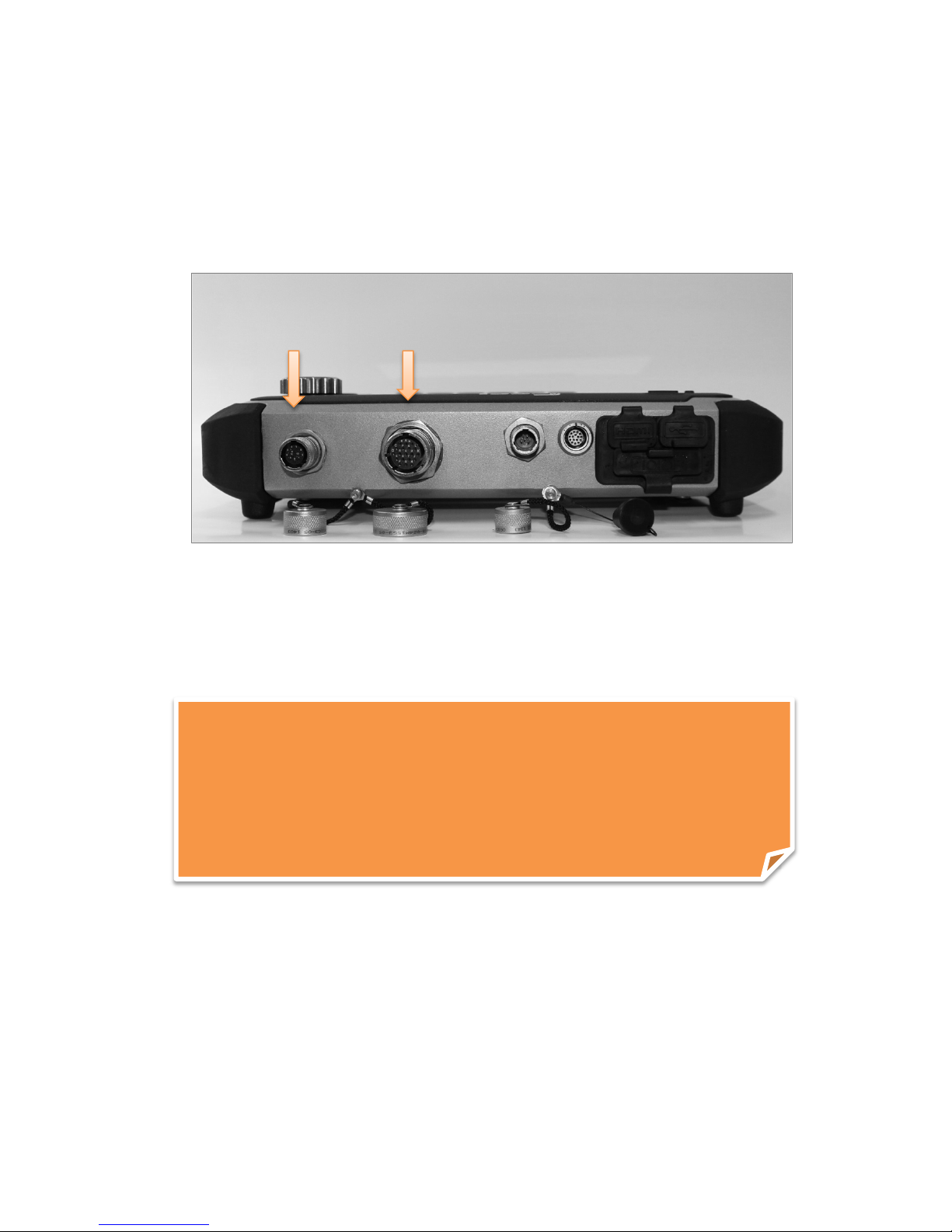
The SIR 4000 has seven connectors located on the top of the unit. Facing the unit from left to right the
connectors are: 13 pin Digital Antenna Connection, 19 pin Analog Antenna Connection, External Power,
GPIO Connector, HDMI Video Out, Serial Port, and USB 2.0.
Video
Antenna
Connector
Out
Digital Antenna Connector: The protruding 13-pin connector at the back of the system is for a GSSI
digital antenna control cable. You will notice the antenna connection on the SIR 4000 has five notches cut
from the metal. These mate with the five raised nubs on the contro l cable to ensure that the pins line up
properly.
• Screw the cable connector collar onto the SIR 4000 to make proper contact. The cable should
only be hand-tightened. Do not use a wrench to tighten the connection as over-tightening will
result in damage. The cable connector collar should be screwed down far enough to cover the red
line on the SIR 4000 connector.
• The only proper time to attach or detach an antenna is with system power off. Be sure to unplug
any external power and to remove the battery before attaching or detaching antennas.
Analog Antenna Connector: The large, protruding 19-pin connector at the back of the system is for the
GSSI analog antenna control cable. You will notice the antenna connection on the SIR 4000 has five
notches cut from the metal. These mate with the five raised nubs on the control cable to ensure that the
pins line up properly.
• Screw the cable connector collar onto the SIR 4000 to make proper contact. The cable should
only be hand-tightened. Do not use a wrench to tighten the connection as over-tightening will
result in damage. The cable connector collar should be screwed down far enough to cover the red
line on the SIR 4000 connector.
• The only proper time to attach or detach an antenna is with system power off. Be sure to unplug
any external power and to remove the battery before attaching or detaching antennas.
External Power Adapter: Plug in the optional AC power adaptor to run the system from 110-240 V,
47-63 Hz power.
MN72-433 Rev D 3
Geophysical Survey Systems, Inc. SIR® 4000
Ethernet
Micro-USB
Manual
GPIO Connector: This is a General Purpose Input/Output connector. It will run a range of future
accessories and peripherals av ailab le from GSSI . Output signals include power and GPS among others.
HDMI Video Out: This will allow you to duplicate the screen on the SIR 4000 when connected to an
external monitor or projector.
Serial I/O (RS232): This is a standard serial connection that can be used to establish communication
between the SIR 4000 and a GPS as well as supply power. Please see Chapter 5: Using a GPS with your
SIR 4000 for additional information.
USB 2.0: This port is for connection to a variety of USB peripherals, including a mouse, keyboard, or
memory device.
• The internal memory capacity is approximately 32 gigabytes. Please see Chapte r 4: Data Trans fer
and File Maintenance for additional information on transfer.
Hardware Connections – Right Side
Micro-USB: The Micro-USB is used to connect an external USB memory device for data transfer.
Ethernet: The Ethernet connection is reserved for fut u re functionality.
MN72-433 Rev D 4
Geophysical Survey Systems, Inc. SIR® 4000
Battery Slot and
Release Arm
Note: It is always recommended to
when storing or transporting the SIR 4000.
Manual
Hardware Connections – Left Side
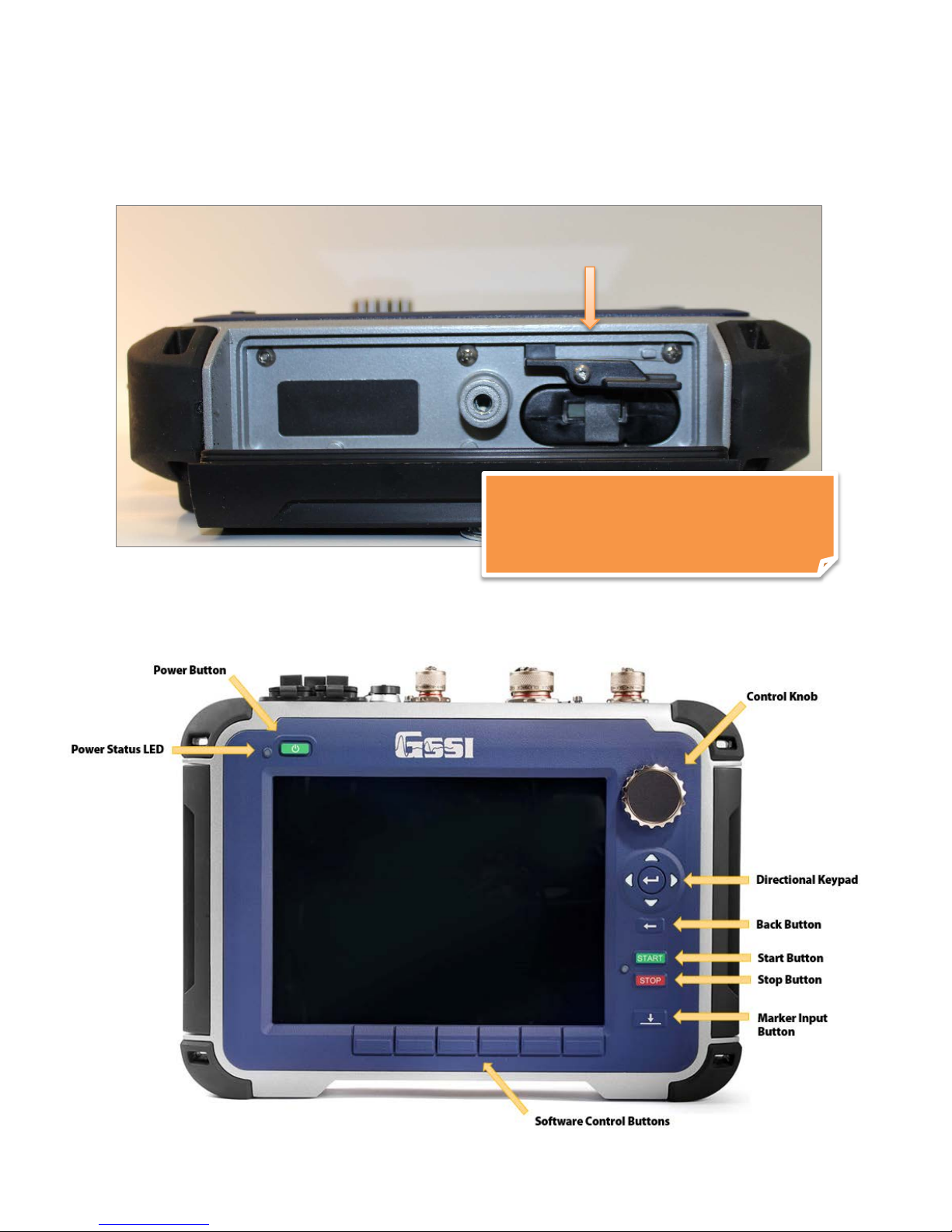
Battery Slot: The battery slot features a release arm, or latch, to secure the battery when one is inserted.
The slot has an eject spring to eject the battery when the latch is released.
remove the battery from the battery slot
Keypad
A built-in keypad, as well as the control knob, will control the SIR 4000. The keypad has sixteen (16)
buttons, two (2) indicator lights, and a control knob. All of the keypad button functions will have
alternative keyboard implementation, except the Power Button.
MN72-433 Rev D 5

Geophysical Survey Systems, Inc. SIR® 4000
Manual
Power Button: This button turns the SIR 4000 on and off. To start up the system, insert a battery or
connect the optional AC power adapter and push the power button.
To turn the system off press and hold the power button for approximately four (4) seconds until the screen
turns black. Should a fault occur it may require ten (10) seconds for the system to respond.
Power Status LED: When the system is turned on the indicator light will flash red. When the system is
ready the LED will remain a solid red.
Control Knob: This knob is used to cycle through the menu tree, quickly change numeric values, and
make selections.
• Turning the knob clockwise moves down through a menu or numeric values. Turning the knob
counter-clockwise moves up through a menu or numeric values.
• Pressing the knob either toggles between On/Off options or enables a secondary menu. After
modifying the secondary option a second press of the knob locks-in the selection.
Directional Keypad: This grouping of five buttons is located right below the wheel. The Enter button is
in the center. These buttons allow you to navigate through the menu tree and make selections.
• Move through the menus by pressing the Up or Down buttons.
• Pressing the Enter button either toggles between On/Off options or enables a secondary menu.
• Modify the menu setting by using either the Up, Down, Left, or Right buttons.
• After modifying the secondary option a second press of the Enter button locks-in the selection.
Back Button: Returns to the main screen from whichever menu is currently selected or open.
Start Button: Begin data collection.
• Short press begins data collection.
• Long press during data collection ends collection of the current file and immediately opens a new
one or prompts you to save or discard the current file. The short press is disabled during data
collection.
Stop Button: End data collection or playback.
• Short press stops data collection.
• Long press ends data collection or playback and return to the main menu.
Marker Input Button: This button is located below the Stop button. Pressing this button while
collecting or playing back data will place a User mark in the data. User marks are used in post-processing
to evenly distribute the number of scans collected in Time Mode between two known points, or marks.
• User marks are helpful for noting distance traveled if you are not using a survey wheel and for
noting the location of objects or obstacles such as columns, trees, pits, etc.
• User marks will appear as long, dashed, vertical red lines through the data window.
• Add user marks by pressing either the Marker Input button on the SIR 4000 keypad or by
pressing the marker button on whichever cart of handle is connected to the system.
Software Control Buttons: Six (6) buttons are located below the display screen and change function
depending upon the current mode in use on the SIR 4000. For a list of each function see Chapter 2:
Getting Started and Expert Mode Setup.
MN72-433 Rev D 6

Geophysical Survey Systems, Inc. SIR® 4000
Manual
1.3 Cautions and Warnings
1 The Display Screen: Do not use alcohol to clean the display screen as this may damage the rubber
gasket around the screen and impact the IP rating. GSSI recommends using warm water or Windex
(or another ammonia-based) cleaner. There is not an anti-glare coating on this screen as there was
with the acrylic SIR 3000 screen protector. The screen is protected by a non-removable chemically
hardened glass.
2 Power off before connection/disconnecting an antenna: GSSI recommends turning off the
SIR 4000 before connecting or disconnecting an antenna. Failure to remove power may cause damage
to the SIR 4000.
3 Weatherproofing: When all of the doors are closed and connections are correctly made the
SIR 4000 is IP65 rated. However, if it does get wet internally, immediately power down the system,
open all of the doors and connections, and leave it for a minimum of 12 hours in a warm dry place.
The SIR 4000 is factory sealed and no attempt should be made to open it.
4 USB Ports: Do not plug two USB drives into the SIR 4000 at the same time. This includes the USB
2.0 Port and the Micro USM Port. You can have a USB device, such as a keyboard or mouse, plugged
in at the same time as USB drive.
Unlike the SIR 3000, the USB ports must not be used to connect the SIR 4000 directly to a computer.
This does not provide any additional functionality.
MN72-433 Rev D 7

Geophysical Survey Systems, Inc. SIR® 4000
Manual
MN72-433 Rev D 8
Geophysical Survey Systems, Inc. SIR® 4000
Manual
Chapter 2: Getting Started and
Expert Mode Setup
In Chapter 2, you will find instructions for connecting all of the hardware inputs and an introduction to
the different menus and functions that are available to you in Expert Mode. Expert Mode allows total
control over all collection parameters and is the most versatile data collection method, usable for all GPR
applications. If desired, 2D profiles can later be transferred to a PC for processing in GSSI’s RADAN
post-processing software.
2.1: Hardware Setup
Hardware setup for the SIR 4000 is very simple. We will use the 400 MHz (Model 50400S) antenna with
single survey wheel for this example. Follow the steps below.
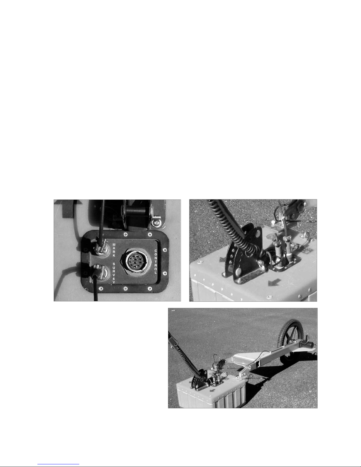
1 Single Survey Wheel Encoder: Attach the survey handle between the two vertical mounting plates
on the top of the antenna with the two removable pins, adjust the angle for comfort, and connect the
marker cable from the handle to the antenna at the MARK port.
2 For Use with the Single Survey
Wheel Encoder: Attach the survey
wheel to the brackets at the back of the
antenna (as shown below) and connect
the cable from the survey wheel to the
SURVEY port on the top of the antenna.
Be sure that the triangular plate
protecting the survey wheel encoder
faces down.
MN72-433 Rev D 9
Geophysical Survey Systems, Inc. SIR® 4000
Note: If you purchased a SIR 4000 with a cart as in the UtilityScan System,
Digital
Analog
Manual
3 Analog Antennas: Connect the female end of the antenna control cable to the antenna.
Then connect the male end to the 19 pin analog antenna connection on the back of the SIR 4000.
Connect the two protective caps together.
4 Digital Antennas: Connect the female end of the antenna cable to the antenna. Then connect the
male end to the 13 pin digital antenna connection on the back of the SIR 4000. Connect the two
protective caps together.
5 Connect power source (battery or optional AC power adapter) to the SIR 4000 and push the power
button to turn on the system.
6 Existing carts may require mounting hardware to attach to the SIR 4000 universal mounting bracket
included with SIR 4000.
or purchased the cart system separately, please see Appendix C: Mounting
Your SIR 4000 on a Cart. The cart also incorporates a survey wheel that is
used in place of the survey wheel pictured here. For a StructureScan Standard
system, please consult the hardware setup instructions in the small, laminated
Quick Start Guide that came with the system.
MN72-433 Rev D 10
Geophysical Survey Systems, Inc. SIR® 4000
Manual
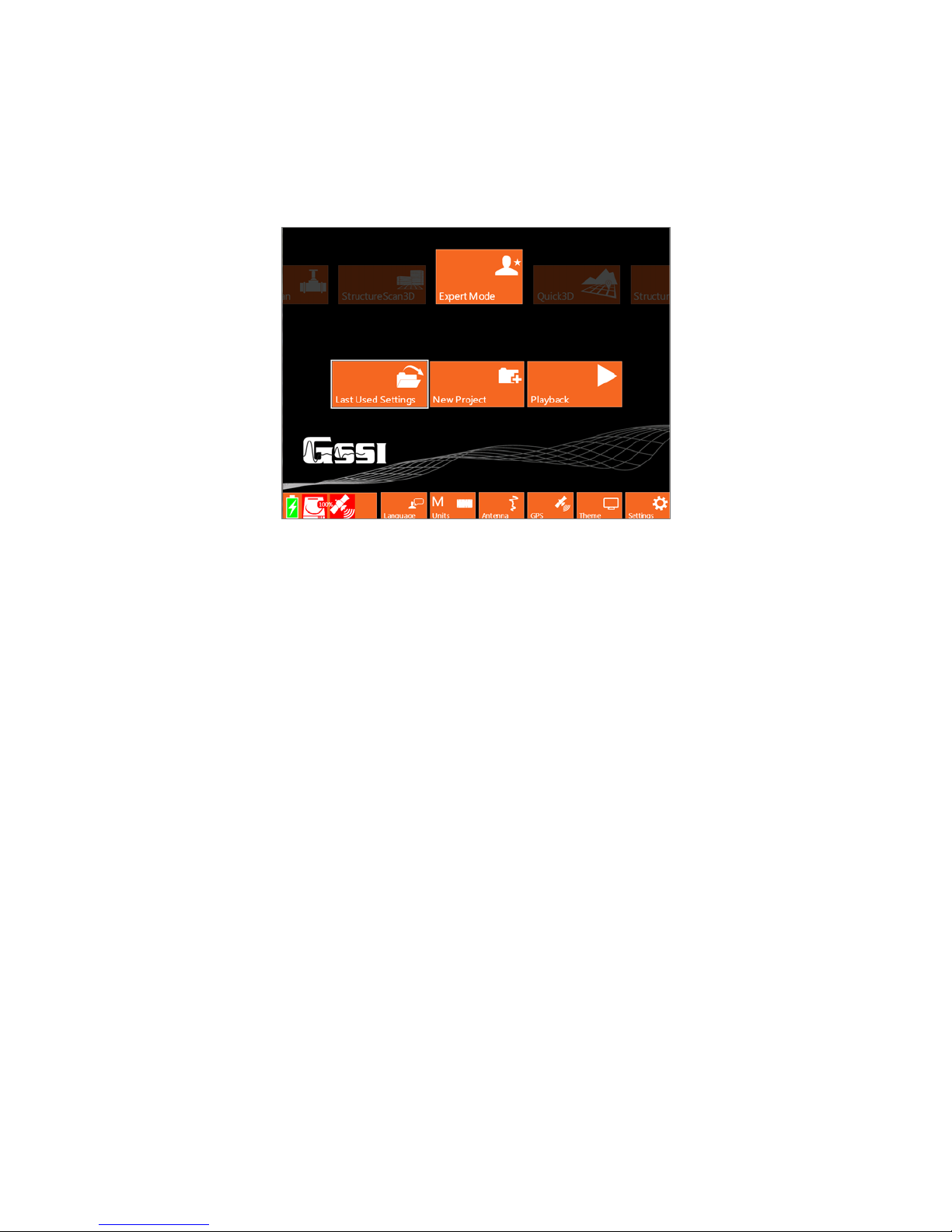
2.2: Introduction Screen
After the SIR 4000 boots up and goes past the splash screen, you will see the Introduction screen. This
screen allows you to select from the following options and modes. It also includes a toolbar at the bottom
and status information.
Modes
The following modes have different options available in the subsequent Setup display based upon
application and whether 2D or 3D data is being collected. Applications that are in development will be
greyed out in the Introduction screen.
Expert Mode
With Expert Mode the user has complete control over all 2D data collection parameters. All parameters in
this mode is customizable, whereas in an application specific mode some options a re limited based on
what is necessary and customary for successful data collection.
Quick 3D
In Quick 3D Mode the user has all of the same controls from Expert Mode as well as options to setup,
collect, and playback data in a 3D grid.
StructureScan 2D
StructureScan 2D provides quick options for locating shallow structural features in concrete and marking
their location directly on the survey surface. The mode is preconfigured for use with high frequency (high
resolution) antennas.
UtilityScan (coming soon)
Similar to StructureScan 2D, UtilityScan provides quick 2D options for locating buried utilities in soils.
StructureScan3D
This mode is for collecting very high resolution 3D data over concrete. The data can be viewed in a
3D cube to identify targets at different depths to help note clear locations for cutting or coring.
MN72-433 Rev D 11
Geophysical Survey Systems, Inc. SIR® 4000
Manual
Last Used Settings, New Project, and Playback
These options allow you to either collect or playback data starting from different points.
Last Used Settings
Starts the system in the last used application mode and project. These may be inappropriate settings if the
antenna was changed.
New Project
Opens a new project in whichever application mode is currently selected and requires you to create a new
Project Name.
Playback
Starts the system in the currently selected mode and prompts you to select a file or multiple files for
playback from the last project selected.
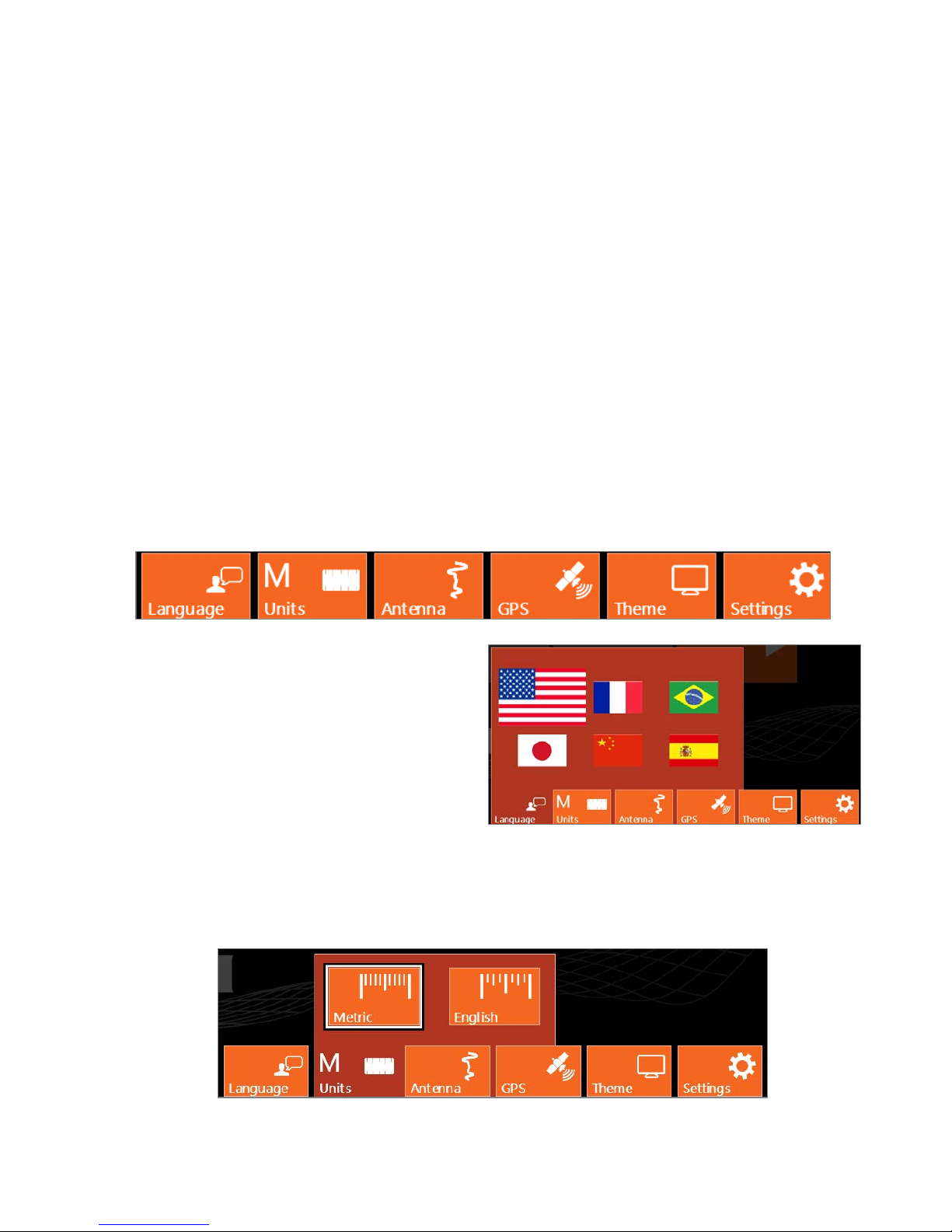
Toolbar
The bottom toolbar provides access to change system settings and universal setup options. Selecting any
of the Software Control buttons, located immediately under each ico n, will open and close each window.
Language
There are six (6) language options on the SIR 4000
including English, Japanese, French, Chinese,
Portuguese, and Spanish. Use the Control Knob or
the Arrow keys to move through the different
languages. Once a language is selected using either
the Control Knob or the Enter button the menu will
automatically close. You can also back out of the
menu by pressing the Back button.
Units
Select between Metric and English Units of measure. Once a unit of measure is selected using either the
Control Knob or the Enter button the menu will automatically close. You can also back out of the menu
by pressing the Back button.
MN72-433 Rev D 12
Geophysical Survey Systems, Inc. SIR® 4000
Manual
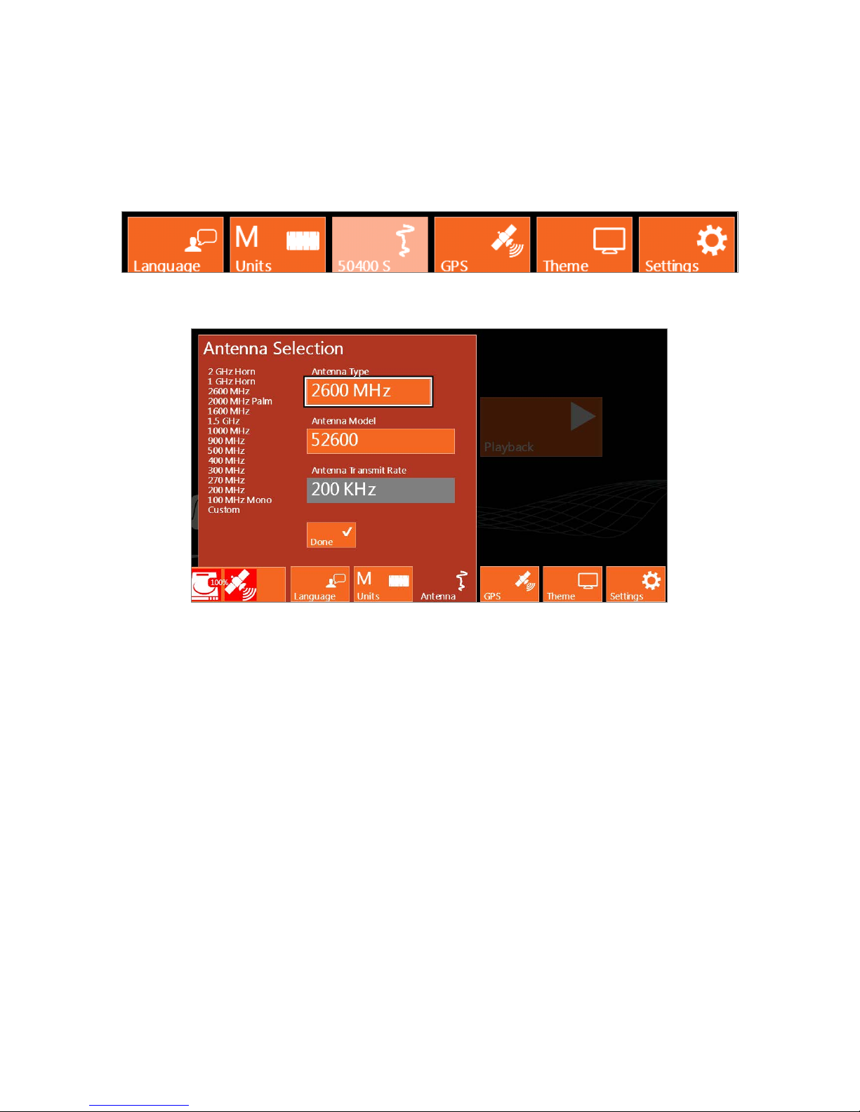
Antenna
This menu is available if you are using an older analog antenna without “Smart ID.” If a digital or “Smart
ID” antenna is connected the system will auto detect the antenna and display the appropriate Antenna
Model on the Antenna button and access to the menu will be disabled. This menu is also disabled when
no antenna is connected.
If an older analog antenna is connected to the SIR 4000 you will be able to select from a list of antenna
frequencies.
Antenna Type: Choose an antenna frequency from the list of available frequencies.
Antenna Model: If multiple models of the chosen Antenna Type are available, you can select which
model of antenna is connected. You can find the antenna model on a sticker affixed to the antenna
housing.
Antenna Transmit Rate: The antenna transmit rate is in KHz, with a Custom rate capped at 100 KHz.
You can modify the antenna transmit rate if Antenna Type is set to Custom. A higher transmit rate
enables faster data collection or more stacking to reduce random noise. Some older antennas are not
capable of transmitting at high speeds and setting them at a high transmit rate may cause an error. Consult
your antenna documentation or call GSSI Tech Support if you have any question about transmit rate. All
GSSI 5100 and 52000 series antennas (2.6 GHz, 2.0 GHz Palm, 1.6 GHz, 1.5 GHz, 1.0 GHz, 400 MHz,
270 MHz, 200 MHz) can be operated at 100-200 KHz. Rates are limited per regulations of the region
where the unit is operated. If you are using another GSSI antenna, consult Appendix E for the proper
transmit rate.
MN72-433 Rev D 13
Geophysical Survey Systems, Inc. SIR® 4000
Manual
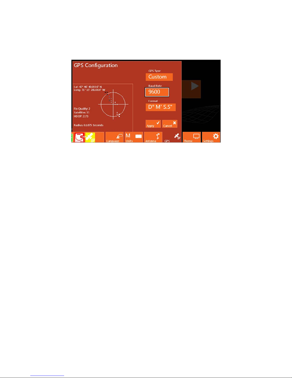
GPS
Allows you to configure your SIR 4000 to collect GPS points during data collection. Make the following
selections to enable GPS collection.
GPS Type: None is set when a GPS is not connected. Custom should be selected if a GPS is connected
and needs to be configured.
Baud Rate: Match the baud rate with the one you are using on your GPS. Available baud rates range
from 4800 up to 230400.
Format: Select which format to use when displaying point, Degrees Minutes Seconds, Degrees Minutes
Decimal Minutes, and Decimal Degrees.
Lat/Long: Displays the currents position in whichever format is currently selected.
Fix Quality: Shows whether or not a GPS or DGPS signal is recording.
Satellites: Displays the number of satellites that are currently in view of the GPS. These satellites are
displayed on the plot in the middle of the GPS Configuration window.
HDOP: The Horizontal Dilution of Precision is the relative accuracy of the horizontal position. The
system needs an HDOP of 2 or less in order to collect data.
Radius: This indicates the size of the Circular Error Probability which appears in the center of the GPS
window as a bull’s eye. This is the radius of a circle, which centers on the mean of the GPS accuracy in
seconds.
Steps to setup the SIR 4000 to match GPS Settings:
1 Connect your GPS to the SIR 4000 through the Serial Port.
2 Turn on your GPS.
3 If planning to recall a default or custom setting, proceed to Last Used Setting or New Project. Select
the saved setup you plan to use and then return to the Introduction Screen.
4 Select the GPS control button.
5 Select Custom from GPS Type.
6 Select the Baud Rate that matches the one set on your GPS.
MN72-433 Rev D 14
Geophysical Survey Systems, Inc. SIR® 4000
Manual
7 Press the green Start button on the right side of the SIR 4000.
8 Wait for the GPS to acquire enough satellites and accuracy so that the HDOP is 2 or less.
9 Press the red Stop button to finish pairing the GPS.
10 Select Apply to save the GPS configuration and exit the menu.
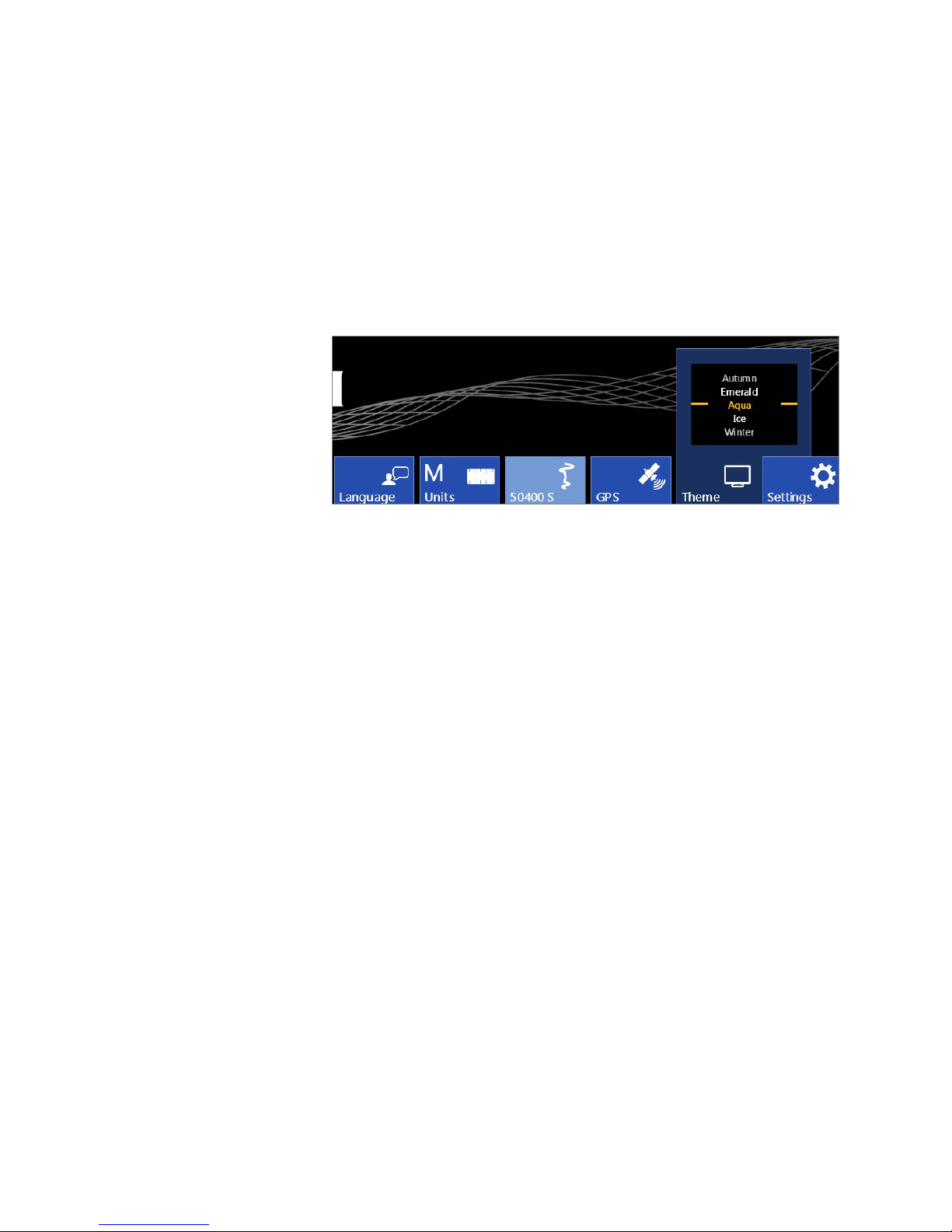
Theme
Select from preformatted color themes for the display on your SIR 4000. Once a theme is selected it will
carry through to any of the modules and become the default for the next time you turn the system on.
Scroll through the different
theme options using either
the Control Knob or the Up
and Down Arrows. Select a
Theme by pushing the
Control Knob or the Enter
key.
MN72-433 Rev D 15

Geophysical Survey Systems, Inc. SIR® 4000
Note:
Manual
Settings
This button opens additional calibration and configuration opt ions. The functions of the Software Control
buttons change to include the following:
Date/Time: Modify the current
Date and Time on the system. Use the
Control Knob to select and modify the
fields. Select Apply using either the
Control Knob or Arrow keys to accept
any changes.
Firmware: View the current
software and firmware
installed on the SIR 4000.
You can also update the
software and firm w are from
this menu by selecting
Update.
Detailed instructions for
updating the SIR 4000
software and firmware are
available in the Appendices.
Verify on the GSSI Support
Website if there is an available
software or firmware update. You
don’t always need to update the
firmware when updating the software.
WiFi: The WiFi configuration is reserved for future functionality.
Quit: Exits the current Settings menu and returns to the Introduction screen.
MN72-433 Rev D 16

Geophysical Survey Systems, Inc. SIR® 4000
Manual
Status
This real-time monitor is always visible during both setup and
data collection. It shows power, storage, and GPS status.
Battery
Shows the current status of the SIR 4000 battery.
AC Power Supply: 255 or more minutes of average run time remaining. This occurs when the SIR 4000
is plugged into AC power.
Green Battery: 30-255 minutes of average run time remaining.
Yellow Battery: 15-29 minutes of average run time remaining. At this level the Battery status icon will
begin to pulse.
Red Battery: Less than 15 minutes of average run time remaining. Battery status icon will continue to
pulse and the battery should be immediately replaced.
Storage
This status icon indicates the amount of used memory on the SD card. The SIR 4000 comes with 32 GB
of internal memory.
GPS
The GPS monitor indicates whether or not a GPS is connected and the quality of the GPS signal.
Green GPS Icon: The GPS is enabled, detected, and the data has an HDOP of 2 or less.
Yellow GPS Icon: The GPS is enabled, detected, and the data has an HDOP greater than 2.
Red GPS Icon: The GPS is enabled, but not detected.
Grey GPS Icon: The GPS is either not enabled in the GPS menu or it is not detected.
MN72-433 Rev D 17

Geophysical Survey Systems, Inc. SIR® 4000
Manual
2.3: Setup Collect/Playback Screen
The SIR 4000 Setup Screen displays a preview of the data, an Information Bat, Setup Menu, and Toolbar.
Information Bar (top): An information bar appears at the very top of the screen and is updated based on
whether the SIR 4000 is currently in Collect or Playback Mode.
• The left-hand side displays the current mode (Distance, Time, Point, or Playback) and file
information (Project Folder – File Name).
• The middle displays GPS coordinates if the system is configured to collect GPS points.
• During collection the right-hand side displays either the scan number if in Time or Point data
collection mode or distance if the Collection Mode is set to Distance.
Main Data Display (left): The main data display window shows a radar profile in linescan format.
Successive single scans are assigned colo r valu es based on amplitude change and displayed next to each
other in sequence to form a continuous image.
• The vertical scale on the left of this data display window shows time, depth, or height.
• New scans will be placed at the right side of the window and data will scroll from right to left.
• The horizontal scale will be in the units of measure selected in the Introduction Screen and with
the density set in the Setup Menu.
MN72-433 Rev D 18
Geophysical Survey Systems, Inc. SIR® 4000
Manual
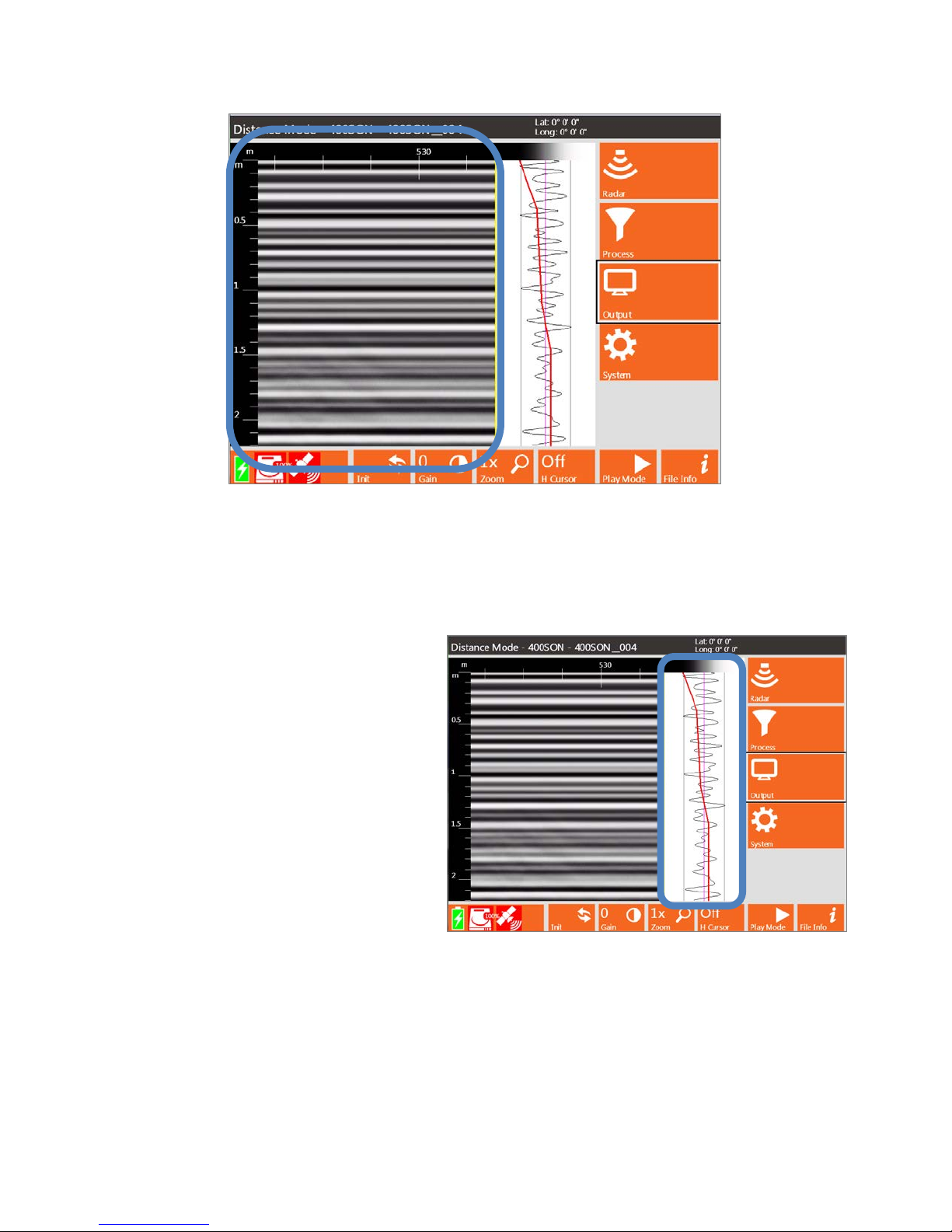
O-Scope (middle): In the middle of the screen you will see a window that shows a single radar scan in
an oscilloscope-style (O-scope) depiction. This will show successive single scans as you move your
antenna across an area while in the Setup Screen.
• Time or depth increases down the screen at the same vertical scale that is selected from the Setup
Menu to the right of the Main Data Display.
• At the top of the window you will see
a color bar. This shows you the
distribution of colors across the range
of reflection amplitudes from
negative, on the left, to positive, on
the right. The exact color and
distribution depends on your choice
of Colormap, Color Stretch, and
Color Slide selected from the Setup
Menu.
• The red line that travels the length of
the O-Scope is the Time Variable
Gain Curve. Refer to the section on
Gain Mode under Setup Menu –
Process for more information on
modifying the gain curve.
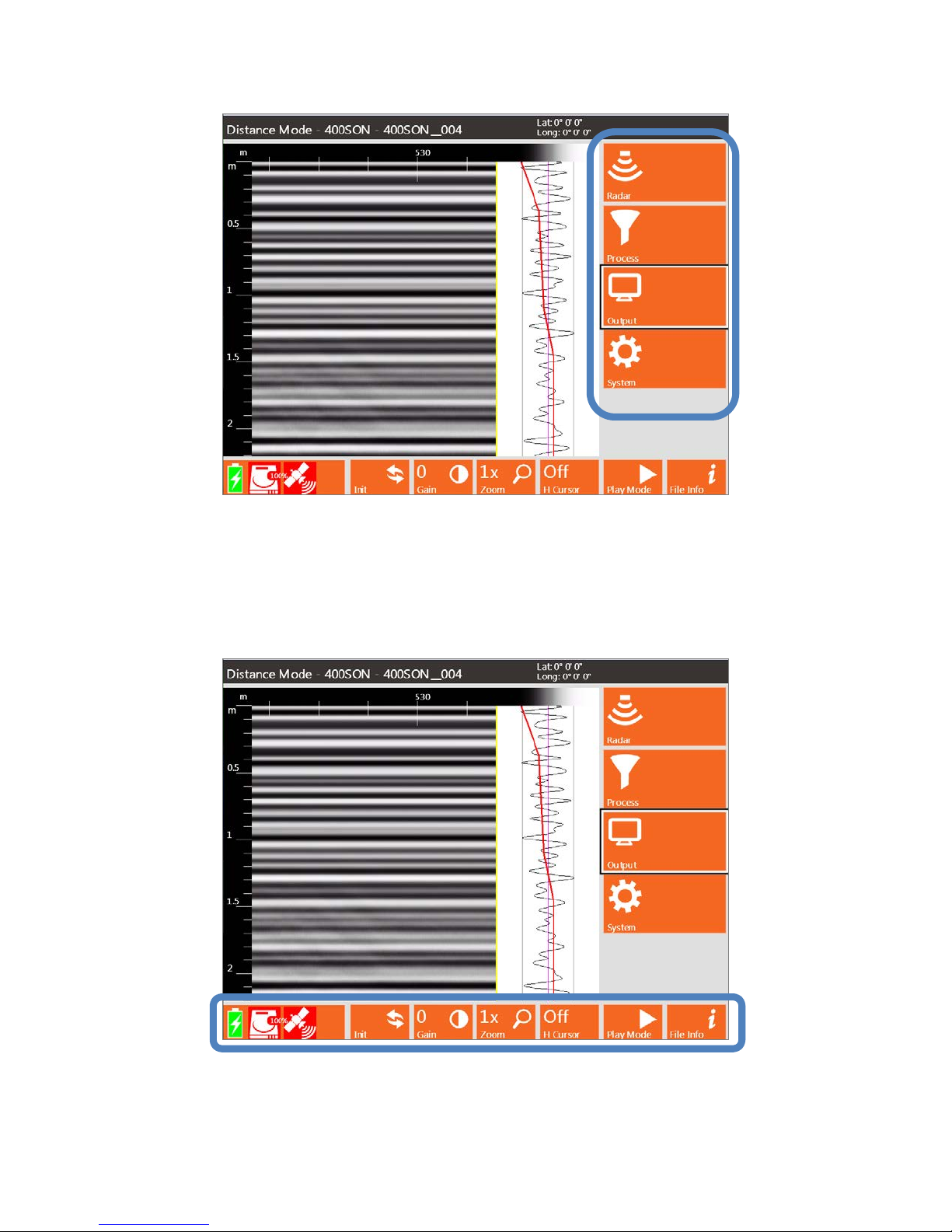
Setup Menu (right): To the right of the O-Scope display is the Setup Menu. This window is where you
will navigate th ro u g h the v arious commands, set system parameters, data paths, colors, and how to save
data. There are four (4) main menu options, Radar, Process, Output, and System. For more information on
each see the sections Setup Menu – Collect Mode or Setup Menu – Playback Mode.
MN72-433 Rev D 19
Geophysical Survey Systems, Inc. SIR® 4000
Manual
Toolbar (bottom): The bar across the bottom of the screen is the Setup or Playback Toolbar and
provides different options for modifying how the data appears during setup, collection, or playback.
Different Applications will have partially customized or completely redefined Toolbars based upon
necessity. In Expert Mode the Toolbar includes Init(ialize), Gain (Display Gain), Zoom (Horizontal
Zoom), Run Mode, Play Mode, and File Info. These commands are each explained in more detail later on
in this chapter when each button is defined.
MN72-433 Rev D 20
Geophysical Survey Systems, Inc. SIR® 4000
Note: Distance-based data
Manual
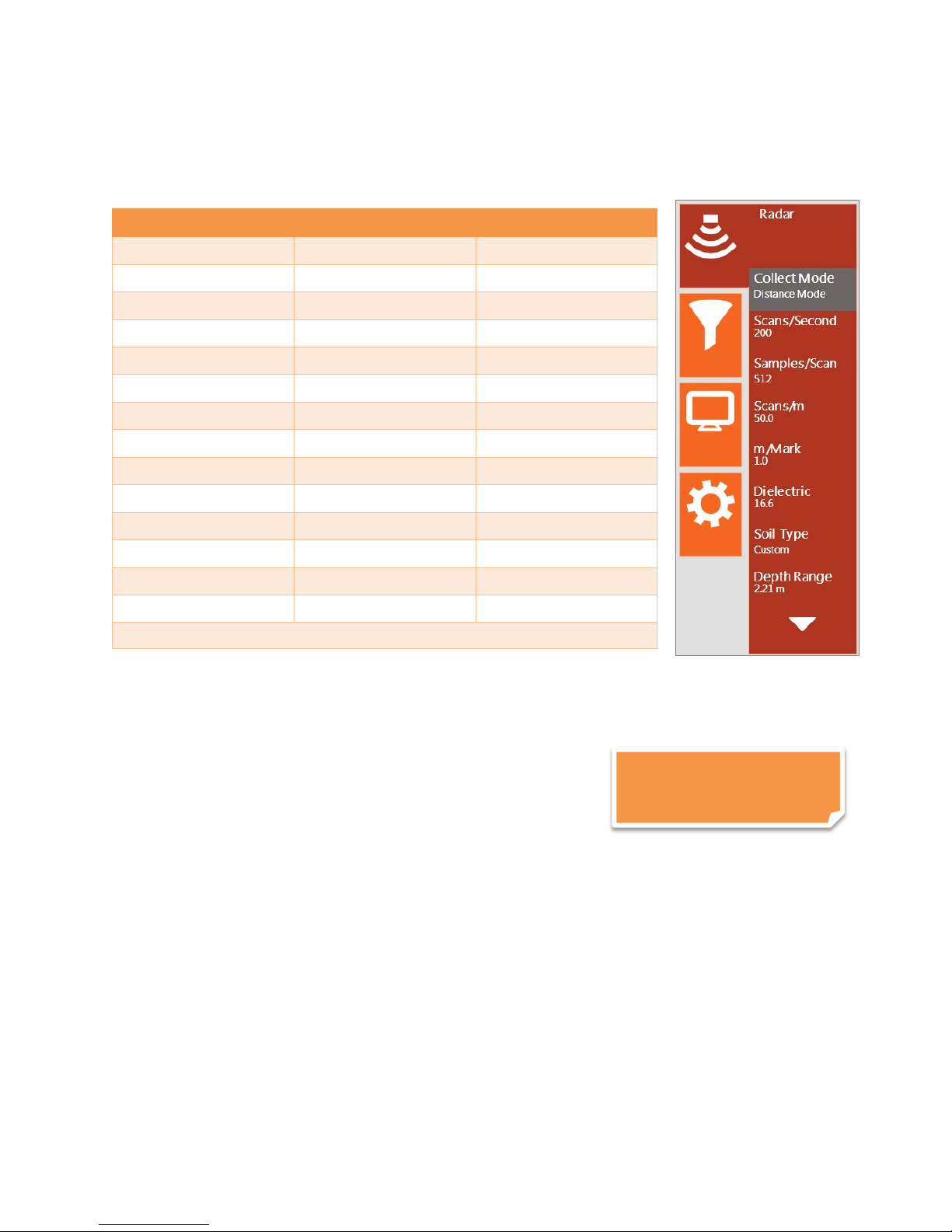
Setup Menu – Radar
Under Radar, there are fourteen (14) settings that can each be accessed by rotating the Control Knob or
using the Directional Keyp ad. The settings are:
Menu Option Collect Mode Playback Mode
Collect Mode X
Scans/Second X
Samples/Scan X
Scans/Unit X
Units/Mark X
Static Stacking* X
Dielectric X X
Soil Type X X
Depth Range X
Time Range X
Position Mode X
Offset X
Surface (%) X
Exit X X
*Available only in Point Mode
Collect Mode
Collect Mode allows you to collect either distance-, time-, or point-based data.
Distance Mode: Distance-based collection is performed with a survey wheel. The system records a
certain number of scans per unit of distance. D ist ance Mod e is more
accurate than Time Mode and it is strongly recommended that you
collect data in this mode if possible. To calibrate the survey wheel
refer to Section 2.2 Introduction Screen – Settings – Calibrate SW.
Time Mode: In time-based data collection, the system is recording a
certain number of scans per second. The data density over an area depends on the speed at which the
antenna is moved over the ground. The rate is set in the Scans/Second setting option. The option is often
used when it is not feasible to use a survey wheel during data collection.
Point Mode: Point-based data collection is commonly selected only for very deep applications or very
difficult terrain. The system will record one scan every time the external marker or Start button is pressed.
The antenna is then moved to the next location and the next scan is collected.
is required for 3D files.
MN72-433 Rev D 21

Geophysical Survey Systems, Inc. SIR® 4000
Manual
Scans/Second
Scans/second is the number of scans the sy stem will collect per second. The SIR 4000 will collect
minimum of 4 and maximum of 400 scans/second.
• If you are collecting data based on time, this is the number of scans that will be saved each
second.
• If you are collecting data based on distance with a survey wheel, this number represents the
maximum possible collect rate. If you exceed this maximum rate the over-speed beeps will sound.
It is recommended that the scans/second be set lower as lower scan rates will auto stack and
improve the signal to noise ratio.
For example if your Scans/Second is set to 60 and you have configured the system to collect 60 scans a
foot, and you move more than one foot per second, the system is going to attempt to collect scans which
are not available. Assuming your Antenna Tra n smit Rate is 200 KHz, the scans/second should be at least
240 whenever you are collecting with a survey wheel and are collecting a max of 512 Samples/Scan.
If you set scans/second higher than possible given the selected transmit rate and the number of
samples/scan, the SIR 4000 will automatically lower it to the maximum possible. Howev er, it is
recommended that the scans/second be set lower than the maximum. This will allow the system to auto
stack points thereby improving the signal to noise ratio.
Samples/Scan
Each scan curve is made up of a set number of individual data points, called Samples. The more samples
you collect, the smoother the scan curve and the better your vertical resolution will be. This also affects
scan speed since the more points collected, the lower the maximum scans/second is set.
• You can choose from a preset list of 256, 512, 1024, 2048, 4096, 8192, or 16384 samples/scan.
FIR filters should only be used with 256-2048 samples/scan.
• As sample number increases, maximum scan rate drops and file size increases.
• GSSI recommends sampling at 512 or 1024 samples/scan for most applications. More samples
will be required for deep geologic or polar ice thickness applications. Below is the equation to use
when choosing a sample rate.
Samples/Scan > ((10*Time Range)/Pulse Duration)
Antenna Model Frequency (MHz) Pulse Duration (ns)
42000S 2 GHz Horn 0.5
41000SA 1 GHz Horn 1
52600S 2.6 GHz 0.4
62000 2 GHz Palm 0.5
51600S 1.6 GHz 0.7
5101 1 GHz 1
3101A 900 MHz 1.1
50400S 400 MHz 2.5
50270S 270 MHz 3.7
5106 200 MHz 5
3207 100 MHz 10
MN72-433 Rev D 22

Geophysical Survey Systems, Inc. SIR® 4000
Manual
Scans/Unit
Scans/unit allows you to adjust the number of scans per unit of horizontal distance. This parameter is the
scan spacing when you are collecting with the survey wheel. A unit of measure will appear based on the
Units selected from the Introduction Screen and the Horizontal Units selected from the Output Menu.
• Smaller scan spacing produces higher resolution data, but larger file sizes, and may require
slower data collection. For example, if you see a 12 here and the system is set to English feet,
rather than Metric units, you will collect 12 scans per foot, or 1 per inch.
• Scan spacing will vary based on application. For example, 5-10 scans/inch (60-120 scans/foo t) is
the optimal rang e for shallow structural features in concrete, but with lower frequency antennas,
like a 400 MHz, a coarser scan density of 12-24 scans/foot is typical.
Units/Mark
You can also set how many units (i.e., feet or meters) will be collected between system marks. These
marks will appear at the top of the data display along the horizontal scale.
Static Stacking
This option is only available in Point Mode. It takes the number of scans entered and averages them
together to output a single scan at each collection location. This is done to minimize high-frequency or
random noise.
Dielectric
Dielectric constant represents the ratio of permittivity of a substance to permittivity in a vacuum. We use
this term to describe how quickly GPR moves through materials. Materials that have a lower dielectric
value allow GPR to propagate more quickly through them.
• If you know the dielectric value of the material through which you are surveying, you can enter it
here and get an in-field time to depth calculation.
• Values range between 1 (air) and 81 (water).
• Higher dielectric values mean slower travel time and shallower penetration. For example, in air,
which has a dielectric constant of 1, radar energy will travel at 12 inches per ns. Since the time
range is in two-way travel time, 1 ns on the vertical scale translates to 6 inches if the DIEL is set
to 1. The distance traveled per ns is reduced by the square roo t of the dielect ric co nstan t. The
dielectric constant of water is 81, so that water slows down the radar wave by a factor of 9
(√81=9). The range in water is thus 6/9 inches per ns.
• Generally speaking, water raises a material’s dielectric constant, and surveys should be performed
on dry material whenever possible.
• The prime determinant of the dielectric constant of soils and sediments is water content, with
wetter areas having a higher value.
• Please see Appendix C for a chart of dielectric values of common materials and a deeper
discussion of dielectrics.
MN72-433 Rev D 23

Geophysical Survey Systems, Inc. SIR® 4000
Manual
Soil Type
Several different Soil Type options are included on the SIR 4000. Selecting a Soil Type will
automatically update the Dielectric with a value which is representative of that soil.
Material Dielectric Constant
Snow/Ice 3.0
Dry Sand 4.0
Pavement 6.0
Rock 8.0
Dry Soil 9.0
Ave. Soil 14.0
Wet Soil 20.0
Wet Sand 25.0
Water 80
Custom
Custom: Will automatically appear if the Dielectric C onstant is manually changed or if either a
hyperbola fitting or ground truth are performed during data collection. For more information on hyperbola
fitting and ground truth see section 2.4 The Command Bar – Output in Collect Mode.
Depth Range
Depth Range is the vertical scale displayed in whichever units are selected under the Output -> Vertical
Units menu.
• Depth Range can be set from 1-10000 cm (0.4-3900 in).
• Modifying Time Range will automatically update the Depth Range.
Time Range
Time Range is the vertical scale in nanoseconds (ns) within which the SIR 4000 will record reflections. It
is proportional to depth viewed because a higher Time Range will allow the energy to penetrate deeper
and return deeper reflections.
• It is important to remember that the Time Range is two-way travel time, so that a range of 50 ns
means that the deepest possible reflector is at 25 ns.
• A very long range may require a greater number of samples in order to create enough data dots
for the scan curve. Refer to the section above about how to determine the appropriate number of
samples/scan.
• Time Range can be set from 1-20000 ns.
• Please see Appendix D for a list of common ranges for individual antennas.
• Modifying Depth Range will automatically update the Time Range.
MN72-433 Rev D 24
 Loading...