

GSSI SIR 30 User Manual


Copyright © 2011-2017 Geophysical Survey Systems, Inc.
All rights reserved
including the right of reproduction
in whole or in part in any form
Published by Geophysical Survey Sy stem s, Inc.
40 Simon Street
Nashua, New Hampshire 03060-3075 USA
Printed in the United States
SIR, RADAN and UtilityScan are registered trademarks of Geophysical Survey Systems, Inc.

Geophysical Survey Systems, Inc. SIR® 30
Manual
Limited Warranty, Limitations of Liability and Restrictions
Geophysical Survey Systems, Inc. hereinafter referred to as GSSI, warrants that for a period of
24 months from the delivery date to the original purchaser this product will be free from defects in
materials and workmanship. EXCEPT FOR THE FOREGOING LIMITED WARRANTY, GSSI
DISCLAIMS ALL WARRANTIES, EXPRESS OR IMPLIED, INCLUDING ANY WARRANTY OF
MERCHANTABILITY OR FITNESS FOR A PARTICULAR PURPOSE. GSSI's obligation is limited to
repairing or replacing parts or equipment which are returned to GSSI, transportation and insurance prepaid, without alteration or further damage, and which in GSSI's judgment, were defective or became
defective during normal use.
GSSI ASSUMES NO LIABILITY FOR ANY DIRECT, INDIRECT, SPECIAL, INCIDENTAL OR
CONSEQUENTIAL DAMAGES OR INJURIES CAUSED BY PROPER OR IMPROPER OPERATION
OF ITS EQUIPMENT, WHETHER OR NOT DEFECTIVE.
Before returning any equipment to GSSI, a Return Material Authorization (RMA) number must be
obtained. Please call the GSSI Customer Service Manager who will assign an RMA number. Be sure to
have the serial number of the unit available.
FCC Class A Compliance
This device complies with Part 15 of the FCC Rules. Operation is subject to the following two conditions:
(1) this device may not cause harmful interference, and (2) this device must accept any interference
received, including interference that may cause undesired operation.
Warning: Changes or modifications to this unit not expressly approved by the party responsible for
compliance could void the user’s authority to operate the equipment.
Note: This equipment has been tested and found to comply with the limits for a Class A digital device,
pursuant to Part 15 of the FCC Rules. These limits are designed to provide reasonable protection against
harmful interference when the equipment is operated in a commercial environment or residential
installation. This equipment generates, uses, and can radiate radio frequency energy and, if not installed
and used in accordance with the introduction manual, may cause harmful interference to radio
communications. However, there is not guarantee that interference will not occur in a particular
installation.
Shielded cables must be used with this unit to ensure compliance with the Class A FCC limits.
Canadian Emissions Requirements
This Class A digital apparatus complies with Canadian ICES-003.
Cet appareil numerique de la classe A est conforme a la norme NMB-003 du Canada.
Notice
Operation is subject to the following two conditions: (1) this device may not cause interference, and (2)
this device must accept any interference, including interference that may cause undesired operation of the
device.

Geophysical Survey Systems, Inc. SIR® 30
Manual

Geophysical Survey Systems, Inc. SIR® 30
Manual
Table of Contents
Chapter 1: Introduction ................................................................................................................1
Unpacking the Box ............................................................................................................... 1
Key New Features of the SIR 30 ....................................................................................... 2
SIR 30 Physical Characteristics and Connections ....................................................... 2
SIR 30 Hardware Setup ....................................................................................................... 4
Chapter 2: User Interface Descriptions ................................................................................ 17
System Start Screen .......................................................................................................... 17
System Settings .................................................................................................................. 18
Main Menu Control Screen ............................................................................................ 21
Main Menu Control Screen\Control Bar..................................................................... 26
RADAR CONFIG .................................................................................................................. 27
SIGNAL PROCESS ............................................................................................................... 41
OUTPUT OPTIONS ............................................................................................................. 47
SYSTEM OPTIONS .............................................................................................................. 57
Chapter 3: Data Collection ........................................................................................................ 59
Data Collection Setup – Single Channel .................................................................... 59
Data Collection Setup – Road Survey with Horn Antennas ................................ 67
Bi Static Data Collection Setup ..................................................................................... 76
Dual-Receiver Data Collection Setup .......................................................................... 83
Chapter 4: Data Playback .......................................................................................................... 85
Single File Playback .......................................................................................................... 85
Dual Channel File Playback ............................................................................................ 90
Multi Channel File Playback ........................................................................................... 93
Chapter 5: Data Transfer ............................................................................................................ 97
Transferring Data from the SIR 30 to the Control Laptop .................................... 97
Transferring Data from the SIR 30 to an External Drive ........................................ 98
Chapter 6: Configuring the SIR 30 with a GPS ................................................................... 99
Appendix A: SIR 30 Pictures ...................................................................................................101
Appendix B: Data Formats ......................................................................................................105
Appendix C: Antenna Specifications ..................................................................................113
Appendix D: Dielectric Values of Common Materials...................................................115
Appendix E: SIR 30 Maintenance Tool Overview ...........................................................117
Appendix F: SIR 30 Wiring Instructions ..............................................................................135
Appendix G: Cable Diagrams .................................................................................................137
Appendix F: Glossary of Terms ..............................................................................................143
MN 93-101Rev E


Geophysical Survey Systems, Inc. SIR® 30
Manual
Chapter 1: Introduction
Thank you for purchasing a SIR® 30 GPR control unit from GSSI. The SIR 30 represents the current state
of the art in high-speed, multi-channel GPR data acquisition systems. The SIR 30 has been designed to
work with any of GSSI’s current and older line of GPR antennas. The SIR 30 also offers many integration
options, so it is easy to integrate GPR to a multi-method data collection vehicle.
Please take a moment to unpack your order and ensure that everything is present. Contact GSSI or your
local GSSI representative immediately if you notice anything missing or damaged. A GSSI representative
can be reached at (603)-893-1109, 8:30 AM – 5:00 PM US Eastern Time, Monday-Friday. You can also
email sales@geophysical.com
GSSI recommends that the User(s) completely review this manual before using your new SIR 30.
Unpacking the Box
Your new SIR 30 comes in a Pelican Model 1650 transit case with custom-cut protective foam. The transit
case has been designed to protect your SIR 30 from the elements and from damage. GSSI recommends
keeping your SIR 30 in its protective case when not in use.
.
The basic SIR 30 system comes with:
• SIR 30 controller
• AC Power supply: Power adapter for powering the SIR 30 from and AC outlet.
• SIR 30 User Manual
• Documentation CD: The CD contains an electronic version of this manual as well as all of
GSSI’s other radar systems and antenna manuals.
• SIR 30 Maintenance Tool: This is a USB Key containing tools to maintain the system and install
updates to your SIR 30 controller and user interface.
• Transit Case: The Pelican 1650 case containing all of the system components.
The User may also want to consider adding some accessories to your SIR 30. These are available from
GSSI as a separate purchase. Optional accessories include:
• A Panasonic ToughBook® laptop computer configured to run the SIR 30 user interface as a client
computer.
• Rugged Ethernet cross connect cable (3 or 7 meter lengths) for connecting the SIR 30 to a laptop
computer.
• DC power cable with battery clips.
• Rugged HDMI cable (2 meters) for connecting the SIR 30 to an HDMI monitor.
• Universal mounting kit for securing the SIR 30 when used in a vehicle.
• RADAN™ 7 data processing and interpretation software.
MN 93-101 Rev E 1
Geophysical Survey Systems, Inc. SIR® 30
Manual
Key New Features of the SIR 30
Increased Data Acquisition Speed: The SIR 30 can transmit at a maximum Pulse Repetition Frequency
(PRF) of 800 KHz. This PRF enables the SIR 30 to collect more than three-quarters of a million samples
per second. Unlike other GPR systems, the maximum PRF is not reduced when operating multiple
channels simultaneously. This unique capability allows the GPR User to collect more data faster than ever
before.
Note: Not all GSSI antennas are capable of operating at the maximum Pulse Repetition Frequency of the
SIR 30. Consult your antenna manual\documentation for the appropriate antenna PRF. Setting the SIR 30
PRF higher than the maximum antenna PRF will result in poor data quality.
Data resolution: The SIR 30 incorporates fixed 32-bit sampling. This means that the SIR 30 has superior
dynamic range than other systems using 8, 16 or 24 bit sampling. The increased dynamic range will enable
the User to recover weaker signals with SIR 30 than other GPR systems.
Data Processing: The SIR 30 system applies filters and gain during data acquisition for display purposes
only. All data is stored raw. The acquisition filters and gain are stored with the data file and will be
automatically applied in RADAN 7 if so desired.
SIR 30 Physical Characteristics and Connections
Front Panel Connectors
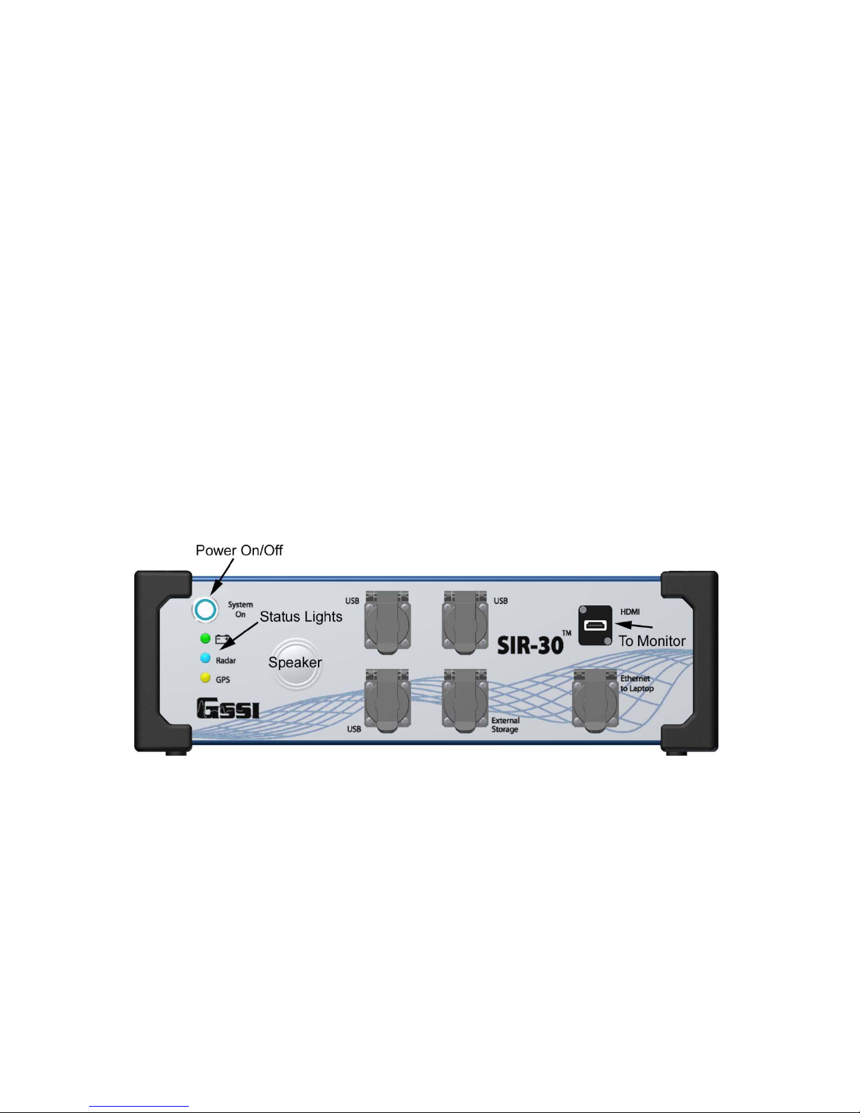
Figure 1: SIR 30 front panel.
The front panel of the SIR 30 has the more frequently accessed connectors as well as the status lights
(Figure 1 above).
Power On/Off: This button will turn the SIR 30 On and Off. To turn on the SIR 30, push this button in so
that it stays depressed. The SIR 30 will begin its boot up sequence. If you are running the user interface
from a separate laptop, there will be no immediate indication from the SIR 30 that it has started. Please be
patient. After approximately 10 seconds, the blue ring around the button will illuminate and you will hear
the SIR 30 cooling fans start. The SIR 30 has completed start-up when you hear a short tone. Push the
power button again to turn off the SIR 30. There will be no immediate indication that the system is
shutting down. After approximately 30 seconds the SIR 30 will complete the shut down process. Please
MN 93-101 Rev E 2
Geophysical Survey Systems, Inc. SIR® 30
Manual
wait for the blue ring light around the power button to go out before unplugging the SIR 30 from its power
supply.
Status Lights: The green LED next to the battery icon will stay lit when the SIR 30 is connected to a
power source. This light will remain illuminated even if the SIR 30 is turned off. The blue LED next to the
word “Radar” will illuminate when power is applied to the internal GPR electronics. The amber LED next
to “GPS” will be illuminated and flash if the SIR 30 detects incoming GPS data.
Note: Do not connect or disconnect an antenna while the SIR 30 is running. Doing so may result in
damage to the SIR 30.
Note: Do not unplug the power supply when the SIR 30 interface is running.
USB ports (3): These are for connecting various USB peripherals, such as a USB mouse and USB
keyboard.
External Storage: This is an Ethernet port for connecting external storage devices such as an Ethernet
hard drive.
Note: The External Storage connection may be labeled as a ‘USB Port’ on some earlier SIR 30 units as it
is a USB port, not an external storage port.
HDMI: This port is for connecting an external HDMI monitor. The user will need to power the HDMI
monitor separately.
Ethernet to Laptop: This port is for connecting the SIR 30 to a computer via an Ethernet link. The user
will need to power the computer separately.
Rear Panel Connectors
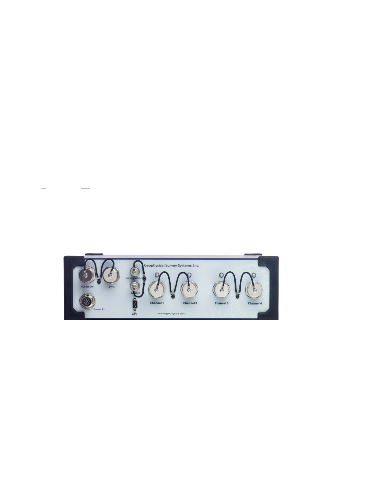
Figure 2: SIR 30 rear panel.
Accessory: This port is for connecting custom accessories to the SIR 30. Contact your GSSI sales
representative for details.
Power In: The connector for the 12 VDC power supply.
Sync: This port is the sync connector for connecting two (2) SIR 30 systems together to create an
8-channel system.
Survey Wheel: This is the connector for any GSSI 4-pin survey wheel or DMI connector.
Marker: The connector for a standard GSSI Model-10 2-pin marker switch.
GPS: This is a 9-pin serial (RS232) connector for an external GPS communications port.
MN 93-101 Rev E 3

Geophysical Survey Systems, Inc. SIR® 30
Manual
Channel 1-2 or 1-4: These ports are for connecting the antenna control cables. GSSI recommends that
you keep the caps on these when the channel is not in use in order to keep them free from dirt and
moisture. There is a LED above each connector which will illuminate when an antenna is connected and
powered up. Be sure to only hand-tighten these as over-tightening may result in damage to the connector.
SIR 30 Hardware Setup
Running the SIR 30 Directly
The SIR 30 controller is a Windows-based PC and may be operated without a separate laptop or PC. To
operate directly from the SIR 30, the user will need a HDMI monitor, a USB keyboard, and an optional
USB mouse. The HDMI Monitor, USB keyboard and USB mouse are not supplied with the SIR 30 system.
With the SIR 30 powered Off:
1 Plug the HDMI monitor cable into the HDMI port on the front panel of the SIR 30 and connect the
monitor’s power cable to its power supply. Turn on the monitor.
2 Plug the USB cable from your keyboard and mouse into one of the free USB ports on the front panel
of the SIR 30. It does not matter which USB port is used for either the keyboard or mouse.
3 Plug the antenna control cable(s) into the channel connectors on the back of the SIR 30.
Note: The antenna-channel hierarchy is as follows:
• 1-Channel: The antenna cable should be connected to the Channel 1 connector.
• 2-Channels: The antenna cables connected to the Channel 1 & Channel 2 connectors.
• 2-Channels: The antenna cables connected to the Channel 1 and Channel 3 connectors.
• 3-Channels: The antenna cables connected to the Channel 1, Channel 2, and
Channel 3 connectors.
Note: Channel 4 may be set up as a CUSTOM channel in a 3 Channel configuration; however it will
record noise ONLY.
• 4-Channels: Antenna cables connected to the Channel 1, 2, 3, and 4 connectors.
4 Ensure that your SIR 30 is connected to an adequate 12VDC power supply and that the
green LED on the front panel of the SIR 30 is illuminated.
5 Push the System On button to turn the SIR 30 on. The User will see the boot sequence information
displayed on the monitor screen. The SIR 30 is fully booted when you see the Windows desktop
SIR 30 start screen.
SIR 30 Shutdown
When powering down the SIR 30, the User may notice that the blue LED next to the word “Radar” will
remain illuminated after the power is turned off. This is normal for some early versions of the SIR 30. If
the SIR 30 has been operated for an extended period, the motherboard will maintain a power-on condition
for several minutes in order to power the CPU cooling fans.
MN 93-101 Rev E 4

Geophysical Survey Systems, Inc. SIR® 30
Manual
Note: Do not connect or disconnect an antenna while the SIR 30 is running. Doing so may result in
damage to the SIR 30.
Note: Do not disconnect the power supply from the SIR 30 when the SIR 30 interface is running.
Running the SIR 30 from a Laptop or PC
The SIR 30 can be controlled from a separate PC running the SIR 30 user interface as a client. The look
and feel of the user interface will be the same as running directly from the SIR 30 controller. You will
need to power the external computer separately.
Note: The User may skip this step if the SIR 30 was purchased with a companion Panaso nic Toughbook
supplied by GSSI. The laptop has already been configured for use with your SIR 30.
Minimum External PC Requirements:
Intel Core i3 or better recommended
3GB System Memory
Windows 7 or Vista (Home or basic versions excluded)
NVidia or Intel Video chipsets
A PC User with Administrator privileges
Configuring the Laptop as a Client
1 Connect your Laptop\Clien t to the SIR 30 with an Ethernet straight connect cable. Turn on the Client\
Laptop and wait for it to boot. Push the System On button to power up the SIR 30. Remember to wait
10 seconds after pushing the button for the SIR 30 to start. The User will hear a Windows start tone
once the SIR 30 is has finished booting.
2 A maintenance tool (a USB thumb drive shipped with the SIR 30) has been provided with the SIR 30
control unit. If the User is configuring their own laptop, they should check the GSSI support site to
insure that they have the latest version. The User should download the latest SIR 30 Maintenance
package from the following URL: https://support.geophysical.com
Note: GSSI always recommends downloading the latest version.
If you have lost\misplaced the USB tool, got to the GSSI support site (at the URL above) and download
the tool. Please follow the instructions below:
Requirements
• Any Windows Vista or Windows 7 computer connected to the internet
• A Clean USB Flash Drive. (512MB or greater in size recommended)
1 Open an internet browser and go to: https://support.geophysical.com/gssiSupport/SIR30Maint.zip.
2 Save the SIR30Maint.zip file to your computer when prompted.
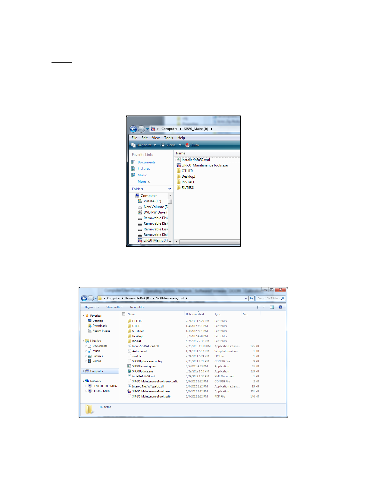
3 Unzip/extract the zip file to a clean USB flash drive. Upon completion, the User should have a
directory that looks like the Figure 3Figure 3 below.
MN 93-101 Rev E 5
Geophysical Survey Systems, Inc. SIR® 30
Manual
4 Turn on the Client\ Laptop and wait for it to boot. Connect the laptop to the SIR 30 with a straight
connect Ethernet cable.
Note: The system will not operate with a cross-connect Ethernet cable. The maximum allowable
Ethernet cable length is 50 m (150 ft).
5 Click the System On button to power up the SIR 30. Remember to wait 10 seconds after pushing the
button for the SIR 30 to start. The User will hear a Windows start tone once the SIR 30 is has finished
booting.
Figure 3: SIR 30 Maintenance Folder with hidden files.
6 If the Windows Explorer Folder Options are set to display hidden files the directory will look like
Figure 4 below.
Figure 4: SIR 30 Maintenance Folder with ‘hidden’ files displayed.
MN 93-101 Rev E 6
Geophysical Survey Systems, Inc. SIR® 30
Manual
The USB drive tool shipped with the SIR 30 has a built in utility designed to search the GSSI support site
for the latest version of the SIR 30 maintenance tool and the latest software and firmware releases.
Updating the SIR 30 Software
Requirements
• Any Windows Vista or Windows 7 computer connected to the Internet
• A PC User with Administrator privileges
Instructions
1 Insert the SIR 30 maintenance tool into the USB port of a computer connected to the Internet.
2 Open the SIR 30 maintenance drive and double-click on SIR30Update.exe to run.
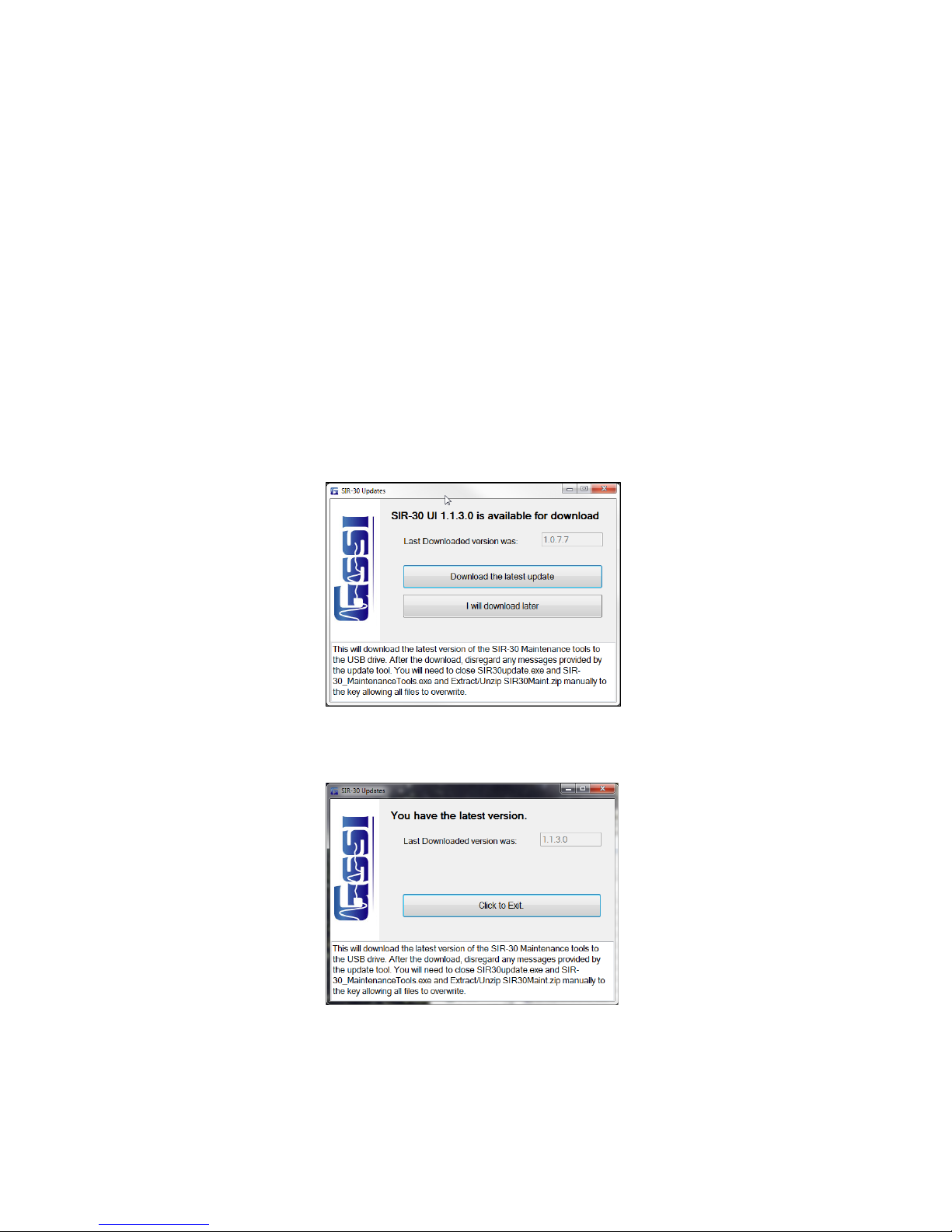
3 The software will automatically attempt to locate the latest version of SIR 30 software and firmware
and compare it to the distribution currently on the maintenance tool (if any). If the tool locates a new
version of the software and firmware, it will display the message in Figure 5 below.
Figure 5: SIR 30 Update available.
If the User has the latest version, the tool will display the message in Figure 6 below.
Figure 6: SIR 30 Software is up to date.
Note: It may take up to 30 seconds after selecting Download the latest update to bring up the SIR 30
update dialog. If the utility locates a newer version, it will ask you if you want to download the latest
version.
MN 93-101 Rev E 7

Geophysical Survey Systems, Inc. SIR® 30
Manual
4 If an update is available, select Down lo ad th e la te s t up d a te.
5 After the download, disregard any messages provided by the update tool. You will need to close
SIR30update.exe and SIR 30_MaintenanceTools.exe and Extract/Unzip SIR30Maint.zip manually
allowing all files to overwrite. This downloads the update files to your USB flash drive and unpacks
them in the appropriate directories. It does NOT install them to your SIR 30 at this time. The
procedure is described below.
Note: After the download is complete, the User will note that the SIR30Maint.zip file is still located on
the USB flash drive. The Unzip\Extract procedure does not automatically delete it. The User can delete it
by hand if desired, or the User may leave it for a future clean up. Some Users may prefer to keep the older
zip files as archives in case they want to restore a previous version of the software.
Laptop Configuration Procedure
Client Computer Requirements
• Windows 7 Business or higher (32 or 64 bit)
• Windows Vista Business or higher (32 or 64 bit)
• Intel Core I-5 or higher recommended
• A PC User with Administrator privileges.
Summary of Configuration Steps
1
Create a SIR 30_Admin User and place the SIR 30_Admin User in the administrative and distributed
COM users groups.
2 Install SIR 30 software after logging in as the SIR 30_Admin User.
a) Reinstall the SIR 30 software.
b) Test the SIR 30 registry.
c) Register the SIR 30 Server.
d) Copy program shortcuts.
e) Connect to server ID.
f) Fix welcome screen.
3 Modify Operating System.
a) Turn off the password requirement.
b) Modify the system power settings.
c) Turn off screen saver.
d) Reconfigure Firewall.
4 Test DCOM Settings.
5 Restart system and Test.
MN 93-101 Rev E 8
Geophysical Survey Systems, Inc. SIR® 30
Manual
Step 1: Create the SIR 30_Admin User
The User should have already gone through the initial steps of setting up your Windows 7 or Windows
Vista computer (“The Windows Out of box experience”) before running the SIR 30 maintenance tool. The
User should not attempt to set up the SIR 30 Administrator or “SIR 30_Admin” User privileges’ during the
out of box experience. If you are setting up the laptop for the first time, create a User named ‘Test’ during
the out of box experience. This will allow the maintenance tool to create a properly formatted SIR 30 user.
1 Insert the USB flash drive containing the SIR 30 Maintenance tool into the laptop computer.
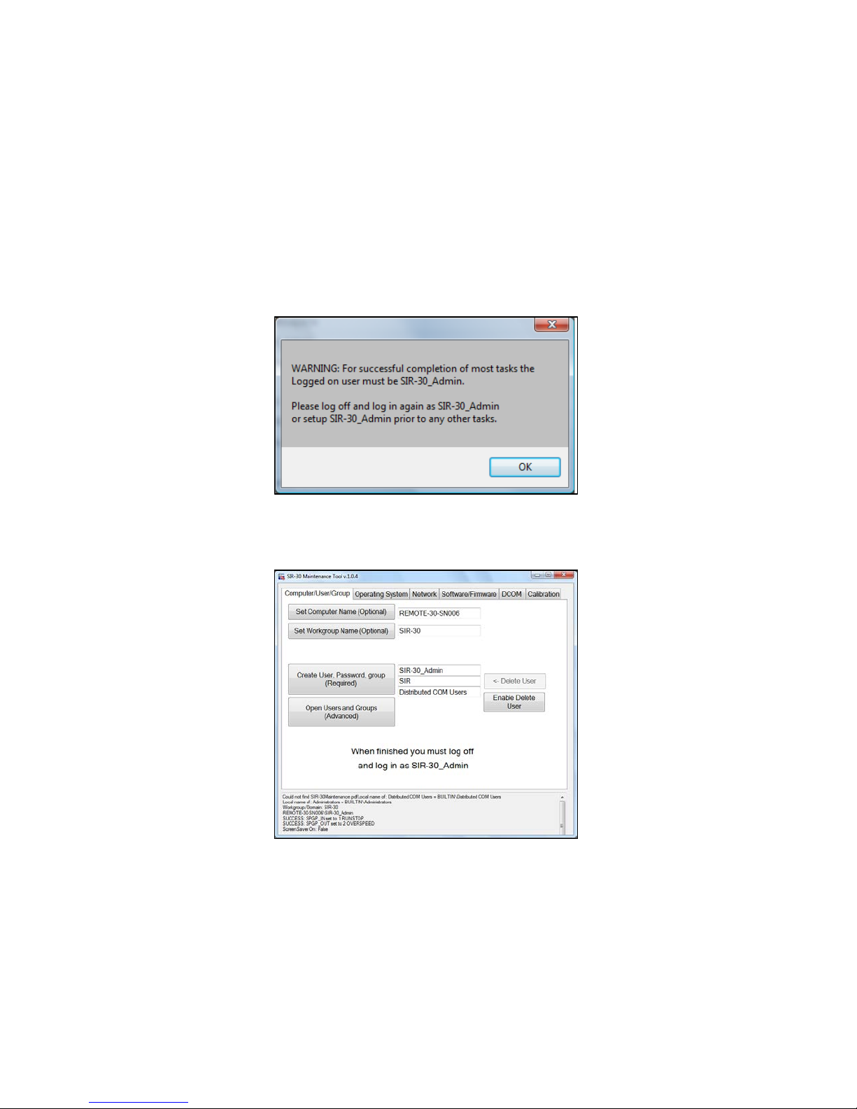
2 To run the SIR 30 MaintenanceTools.exe, right-click and select Run as Administrator. The system will
display a warning if the User is not logged on with administrator privileges i.e., SIR 30_Admin.
Figure 7: SIR 30 Administrator Warning.
3 When the SIR 30 maintenance tool opens, the system will display the SIR 30 Maintenance Tool menu.
Figure 8: SIR 30 Maintenance Tool – Set Computer/User Group.
4 Select the Computer User/Group tab.
5 Click the Set Workgroup Name button.
MN 93-101 Rev E 9
Geophysical Survey Systems, Inc. SIR® 30
Manual
6 Click the Create User, Password, Group button and set the computer and the workgroup name.
Set the User to SIR 30_Admin.
Set the default User to SIR.
Note: The User should perform this step even if they (erroneously) crea ted the SIR 30_Admin
user during the Windows “Out of Box” experience.
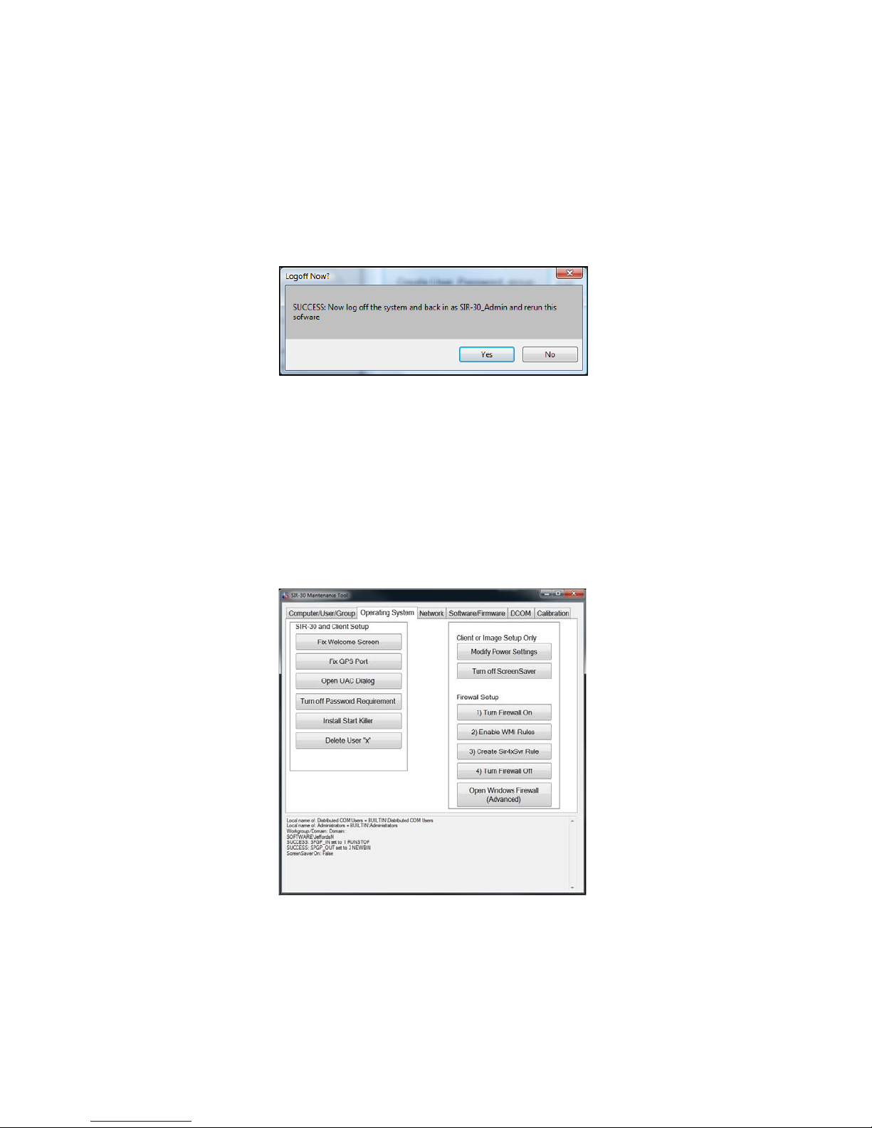
7 Click Yes to Log out, then log back in as SIR 30Administrator as directed.
Figure 9: Administrator Log off.
Step 2: Modify the Operating System
1
Log back in to the computer as SIR 30_Admin if you have not already done so and run the
Maintenance tool again.
• Username: SIR 30_Admin
• Password: SIR
2 Run the SIR 30-MaintenanceTools.exe again.
Figure 10: Modify Operating System.
3 Select the Operating System tab from the Tool menu and then select the following functions. (See
Figure 10 above)
Note: Please wait for the completion of each step before proceeding to the next.
MN 93-101 Rev E 10
Geophysical Survey Systems, Inc. SIR® 30
Manual
4 Click the Fix Welcome Screen button.
5 Click the Fix GPS Port button.
6 Click Open UAC Dialog (User Account Control) button and select Never Notify > Accept.
Note: If your computer is running the Vista operating system, you will have to use the Windows
Control panel to find the UAC dialog.
7 Click the Turn Off Password Requirement button.
Note: DO NOT REMOVE THE PASSWORD. Follow the onscreen dialog instructions and uncheck
the checkbox. The User will see a black dialog flash on screen several times.
a) Go to the Client or Image Setup Only column and click the Modify Power Settings button.
b) Click the Turn Off the Screen Saver button.
c) Under Firewall Setup, click the Enable WMI Rules button.
d) Click the Create Sir4xSvr Rule button.
e) Click the Turn the Firewall Off button.
f) Return to the SIR 30 and Client Setup column.
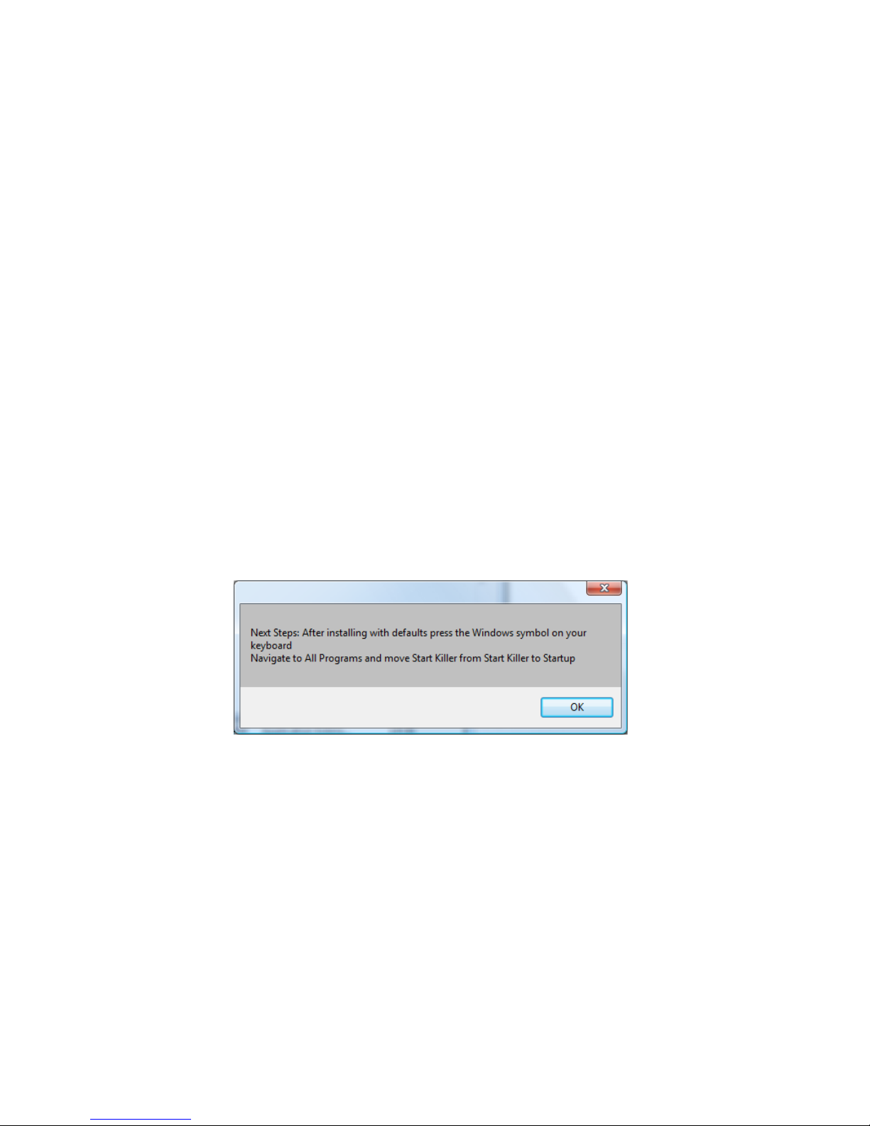
g) Click the Insta ll Sta r t Kil ler button.
8 The User should follow each step of the install instructi on s. Upon completion, the User will receiv e
addition instructions.
Figure 11: Move Start Killer.
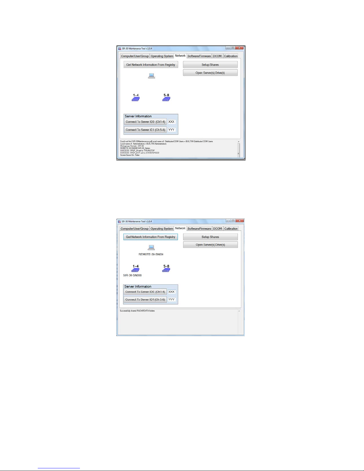
Step 3: Modify the Network
1
Select the Netwo rk tab.
2 Go to the Server Information panel at the bottom left to specify the Serial Number of the SIR 30
system the User is configuring. Enter the last three digits of the serial number of the SIR 30 control
unit in place of XXX and click the Connect to Server ID0 (Ch 1-4) button.
MN 93-101 Rev E 11
Geophysical Survey Systems, Inc. SIR® 30
Manual
Figure 12: Modify Network tab.
Note: If the User is configuring an eight (8) channel system the User will also have to click Connect
to Server ID1(Ch 5-8) button and enter the Serial Number of the SIR 30 control unit being used for
channels five (5) through eight (8) before selecting the Setup Shares function.
3 Click the Setup Shares button.
Figure 13: Setup Shares Successful.
4 Close the SIR 30 MaintenanceTools utility.
5 Log Off the computer.
6 Install SIR 30 Software.
7 Log back in to the computer as SIR 30_Admin.
• Username: SIR 30_Admin
• Password: SIR
MN 93-101 Rev E 12
Geophysical Survey Systems, Inc. SIR® 30
Manual
Step 4: Re-Install SIR 30 Software
1
Navigate to the Control Panel > Users > User Accounts > Turn User Account Control On or Off.
2 Turn Off the User Account Control (UAC).
3 Run the SIR 30 MaintenanceTools program again.
4 Select the Software/Firmware tab.
a) Click the ON button under Typical F irs t T ime Install.
b) Click Re/Install SIR 30 Software button. Please wait for installation to complete.
c) Clickt the Regis te r Serv er button. A black Windows DOS screen will appear and REGRGS dialog
will appear. Click OK. The system will now install several *.DLL files. Click OK after each
installation.
d) Click the Copy Shortcuts button.
e) Click the Test SIR 30 Registry button.
f) If the User owns or has purchased horn antennas which are to be used with the SIR 30, click the
Copy Custom Filters to SIR 30 dir button.
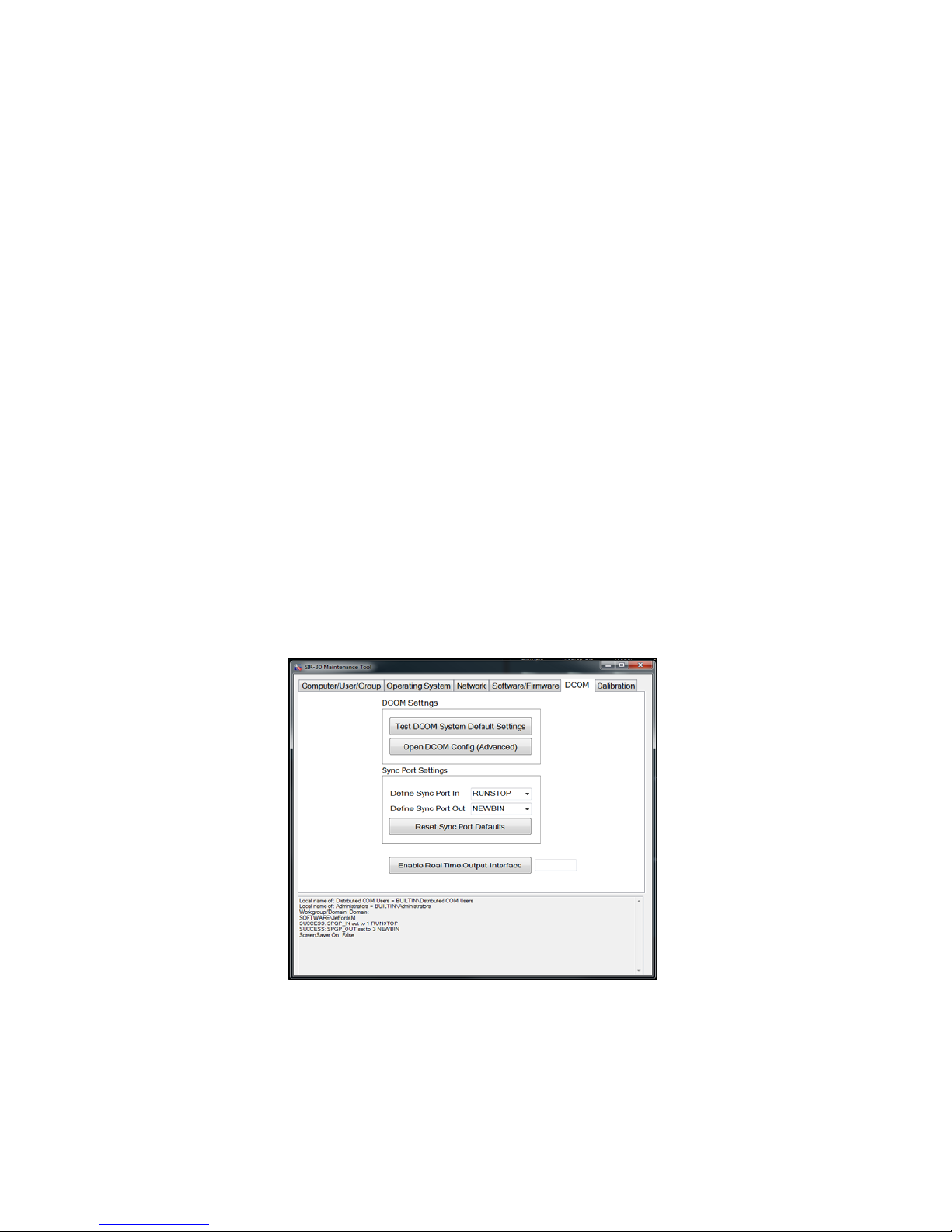
Step 5: Test DCOM Settings
Select the DCOM tab.
1
2 Click the Test DCOM System Default Settings button.
Figure 14: Test DCOM Settings.
3 Log off and shut down the client computer and the SIR 30 control unit.
MN 93-101 Rev E 13

Geophysical Survey Systems, Inc. SIR® 30
Manual
Step 6: Restart and Test
1
Restart the Clie nt P C .
2 Restart the SIR 30.
3 Wait for both systems to boot.
4 Select either the English or Metric the SIR 30 user interface on the Client PC.
5 If the installation\configuration has failed at some step in the above procedure, the computer will
display a “Cannot find SIR 30 Sever” message and the user interface will not start. Please follow the
steps below to trouble shoot the system.
Troubleshooting SIR 30 Client Computer Connectivity Issues
If the User is experiencing connectivity problems between the SIR 30 and client, the User should first
check that the Ethernet cable is connected and that the cable is a straight connect cable.
Re-cycle the power on both the laptop and SIR 30 and wait for them to boo. Please wait 10 seconds after
pushing the button for the SIR 30 to start. You will hear a Windows start tone once the SIR 30 is has
booted up.
Requirements for Connectivity
• A SIR 30 \Laptop-Client connection.
• The Server Computer Name: SIR 30-SNXXX \YYY where XXX\YYY is the last 3 digits of the
control unit serial number.
• User Name: SIR 30_Admin
• Password: SIR
• The SIR4xSvr DCOM settings must match those detailed above.
• Firewall settings that have been configured by the Maintenance Tool.
• The SIR 30 C: drive RADARDATA directory sharing set to Read/Write for Everyone.
• Straight connect Ethernet c able to connect SIR 30 and Client computer. If the User has the SIR 30
connected to a network, check to make sure that it works with a direct connection before contacting
GSSI.
Note: If you are running the SIR 30 through a switch, the User will need to troubleshoot any switch
connectivity issues with your IT department.
• A Client Computer that has been successfully configured using the SIR 30 maintenance tool as
described in the previous section.
• SIR 30 UI and Server with SIR 30 Firewall settings configured by the Maintenance Tool.
If you are still having trouble, please test the following before contacting GSSI:
• Verify that the SIR 30 is running.
• Verify that the Client computer is running.
MN 93-101 Rev E 14
Geophysical Survey Systems, Inc. SIR® 30
Manual
• Verify that the User Account Control (UAC) feature is turned Off.
• Verify that you have the SIR 30 shortcuts set to Run as Administrator.
• Verify that both the SIR 30 and the Client have an adequate power source. Running the client laptop
off the laptop battery for extended periods can result in degraded performance and intermittent
connections.
• Check the Ethernet connections between the SIR 30 and Client.
• Consider replacing the Ethernet cable between the SIR 30 and Client.
• Disconnect from network switch (if one is being used) and use a direct connection.
• With the SIR 30 and Laptop-computer\client connected by a direct connect Ethernet cable; verify that
you can see the SIR 30 Serial Number from Windows Explorer on the Client.
• Repeat all the steps in the Client setup guide.
When running the SIR 30 user interface if you are having trouble copying files to the client computer or a
remote drive using COPY TO LAPTOP, COPY TO DRIVE E or COPY TO DRIVE F, check for the
proper setup to your destination RADARDATA drive as follows:
1 Navigate with Windows Explore to the root of your destination drive e.g. C:\ for COPY TO LAPTOP.
2 Look for the RADARDATA directory.
a) If it does not exist, create a RADARDATA directory.
b) Right-click on RADARDATA and select Share.
c) Add Everyone to the share list and assig n Read /W ri te perm issi ons to Everyone.
3 Run the SIR 30 MaintenaceTools utility.
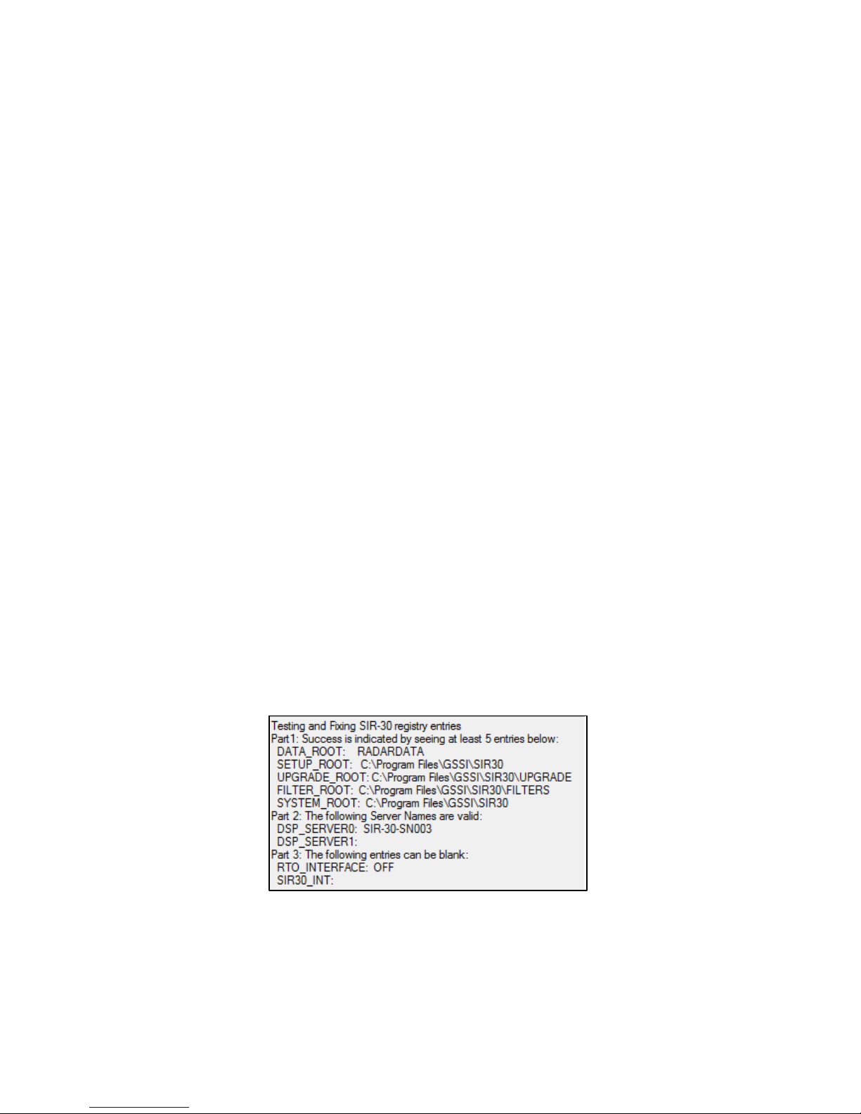
4 Navigate to the Software/Firmware tab, then click the Test SIR 30 Registry button, and verify that
your servers are valid. The Server names are found under “Part 2”. The Server name format is SIR 30SN ###.
Figure 15: Test SIR 30 registry – Test Servers.
Important Note: There is one DCOM setting on the SIR 30 (the ‘Host’) that must be set by hand.
The SIR 30 Maintenance tool cannot access it. The setting has been applied at the factory by GSSI ,
however if it is changed or if SIR 30 software is uninstalled on the SIR 30, it would need to be re-set
by hand. To check this setting:
MN 93-101 Rev E 15
Geophysical Survey Systems, Inc. SIR® 30
Manual
5 Insert the SIR 30 Maintenance tool into a USB port on your computer.
6 Run the SIR 30 MaintenanceTools and select Run as Administrator.
7 Navigate to the DCOM Tab and click the Open DCOM Config. button.
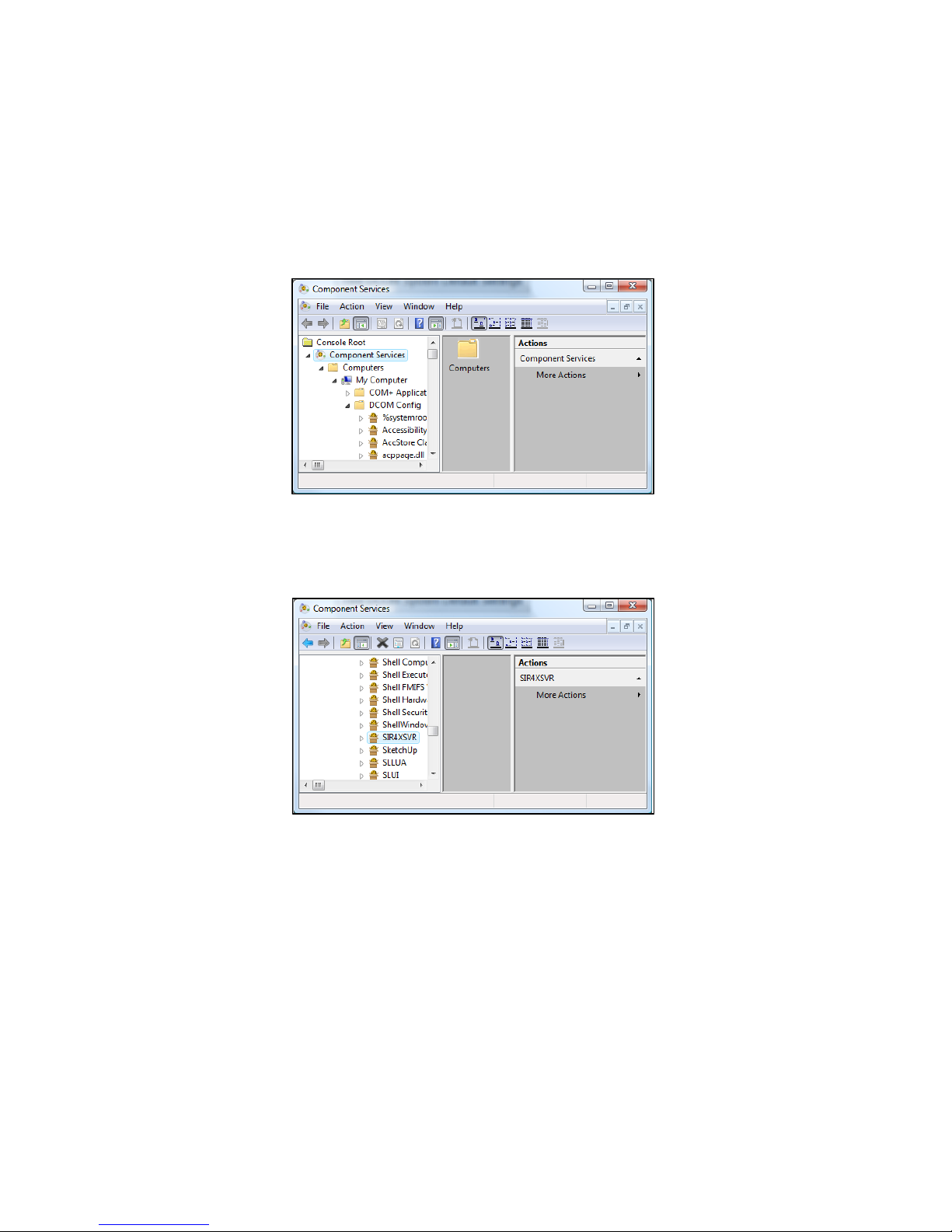
8 On the Component Service Dialog and selec t Com ponent Services > Computers > My Computer >
DCOM Config. The Component Services dialog should look like Figure 16 below.
Figure 16: Component Services.
9 The User will need to scroll down the list to DCOM Config. Open the DCOM Config folder and scroll
down to SIR4XSVR.
Figure 17: SIR4XSVR.
a) Right-click on it and select Properties.
b) When the Properties dialog appea rs, selec t the I dentity tab. Specify the User as:
o User: SIR 30_Admin
o Password: SIR
c) Confirm the Password: SIR
d) When the User has finished checking\modifying the information, click OK to apply.
If these steps fail to resolve connectivity issues please contact your sales representative or the GSSI Field
Service department.
MN 93-101 Rev E 16
Geophysical Survey Systems, Inc. SIR® 30
Manual
Chapter 2: User Interface Descriptions
This section will familiarize the User with the various menus of the SIR 30. GSSI recommends that the
User read this section carefully to gain an understanding of the menu structure and UI (User Interface).
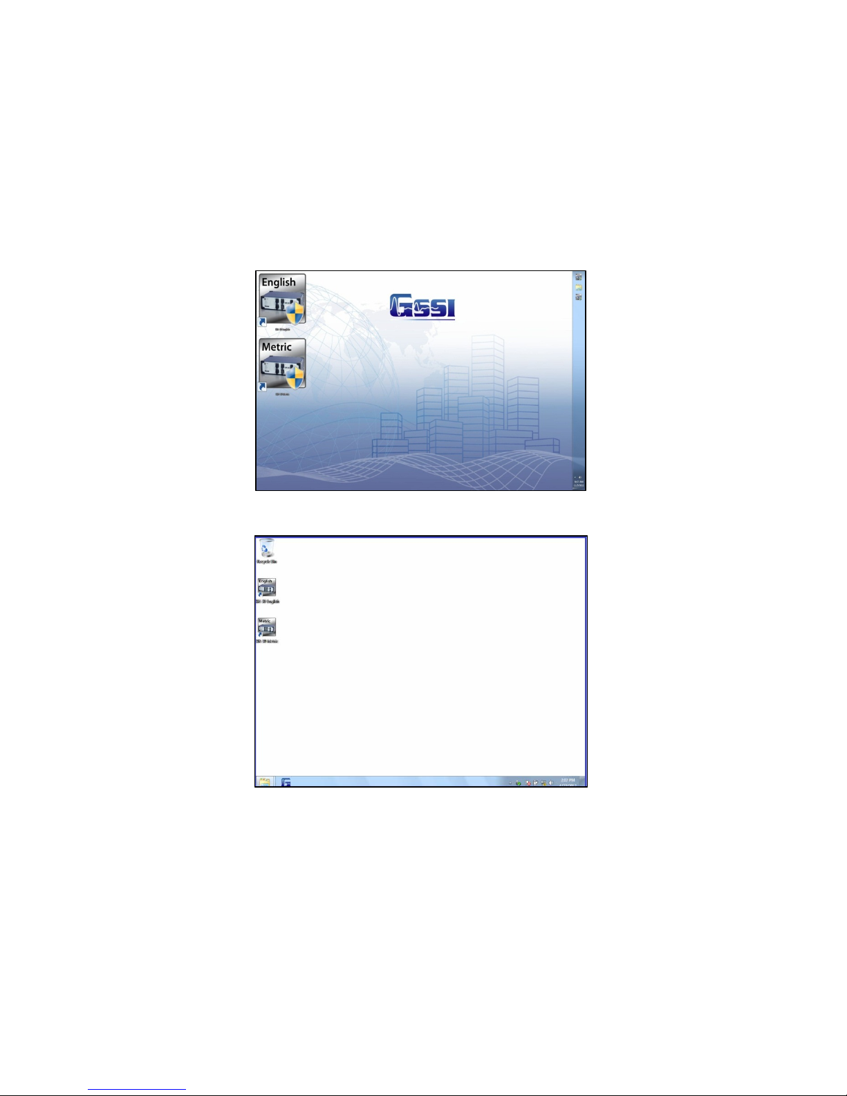
System Start Screen
Figure 18: HDMI SIR 30 server system start screen.
Figure 19: Laptop system start screen.
After powering up the SIR 30, the system display will present the Start screen as illustrated in Figure 18
above. The User must select the system of linear units; either Metric or English, to be used for the survey.
Once the User has selected the system of units, the SIR 30 will present the System Setting Screen.
Note: Once the user has selected a system of linear units for a survey, these units cannot be changed
during data collection.
MN 93-101 Rev E 17
Geophysical Survey Systems, Inc. SIR® 30
Manual
System Settings
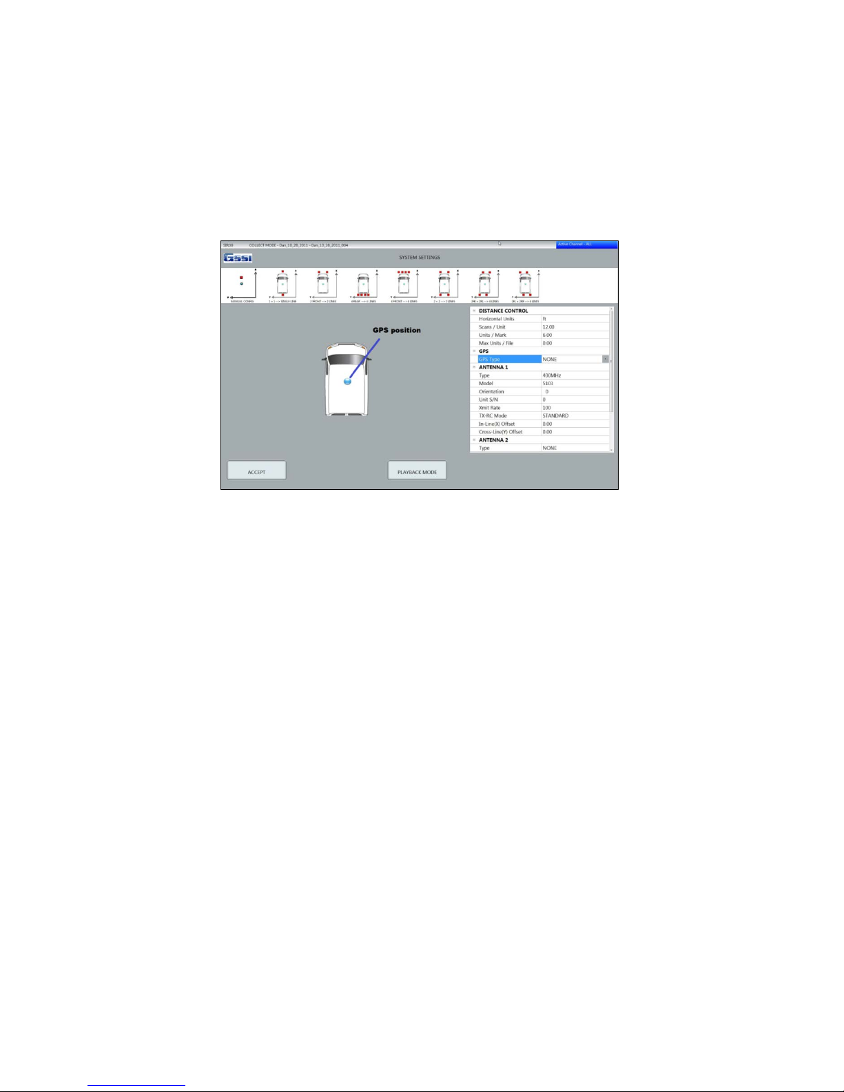
After selecting the desired linear units from the SIR 30 start screen, the SIR 30 will display the System
Settings menu shown in Figure 20 below. It is here that the User will specify the geometry of the data
collection setup i.e. the position and location of the antenna(s) relative to the location of the GPS receiver,
the offset distances of the GPR antennas from the GPS receiver, the desired scan density and mark spacing
as well as specify the type of antenna(s) connected to the system.
Figure 20: Initial system settings.
DISTANCE CONTROL
These parameters control the horizontal scan density. The horizontal scan density, or Scans per Unit
distance is recorded in the units selected by the User from the System Start screen. In Figure 20 (above),
the option shown is 12 scans\ft. The horizontal scan density should be set high enough so that the smallest
feature of interest is detectable yet not so high that large amounts of extraneous data are collected. The
horizontal scan density required for a specific application is dependent on many factors including the
electrical properties of the media and the target or structure of interest, the wavelength of the antenna
center frequency, the speed at which the data is collected, the depth of the targets, their size, etc.
UNIT/MARK: This setting controls how often the SIR 30 will write a distance mark in the data file and on
the data acquisition display. Distance marks provide the User a quick visual indicator of distance travelled
The Unit/Mark setting is stored in the radar file header.
MAX UNITS/FILE: This setting controls the total expected size of an individual data file distance units.
When you start data collection, the SIR 30 will reserve a block memory sufficient to store the file. This
number does not need to be exact. If you leave this setting at the default value of zero (0), the SIR 30 will
reserve a memory block equivalent to 5 GB per channel.
The User has been provided with a service utility called Sir30 Calc.exe. It is located on the USB
Maintenance Tool, which shipped with your system. This tool allows the User to input any data collection
parameters that will affect the File Size, Scan Rate, Scans per Unit, Scans per Second, Samples per Scan,
Units, Max Units/File, Distance, Transmit rate of SLOWEST Antenna and Channel Configuration. By
changing various parameters, the User can determine the following:
• The maximum scan rate (Scans per Second) possible with a given configuration.
• The maximum speed of data collection (Km/h or M/h) possible with a given configuration.
MN 93-101 Rev E 18

Geophysical Survey Systems, Inc. SIR® 30
Manual
• The output file size (in GB).
• The Maximum Units per file.
• The data improvement factor. This is equal to the number of repeats per sample.
GPS
If you are using a GPS with the SIR 30, select CUSTOM from the GPS Type and enter the location of the
GPS receiver antenna wi th resp ect to the GPR antenna connected to Channel 1. If the GPS antenna is
mounted to the Channel 1 GPR antenna, both the X and Y values will be zero (0). If the GPS antenna
location is behind the Channel 1 antenna location, the X value will be the distance of the GPS behind the
GPR antenna, and the number will be negative. The Y value determines how far to the right or left the GPS
is relative to the GPR antenna connected to Channel 1. If you are standing behind the antenna, facing in
the direction of your survey profile, this number will be positive if the GPS antenna location is to the left
of the GPR antenna and negative if the GPS antenna location is to the right of the GPR antenna.
Figure 21: GPS set to CUSTOM, GPS is enabled.
Figure 22: GPS\GPR Antenna position configurations.
The diagram at the top of the System Settings menu provides the User with a quick visual aid for
describing the GPR antenna position relative to the GPS antenna location (Figure 22). The GPS offset
positions (if any) are saved as the In-line (X) and Cross-Line (Y) offset values in the file header and are
used by RADAN 7 to correct the antenna offset positions for processing multi-channel files .
MN 93-101 Rev E 19
Geophysical Survey Systems, Inc. SIR® 30
Manual
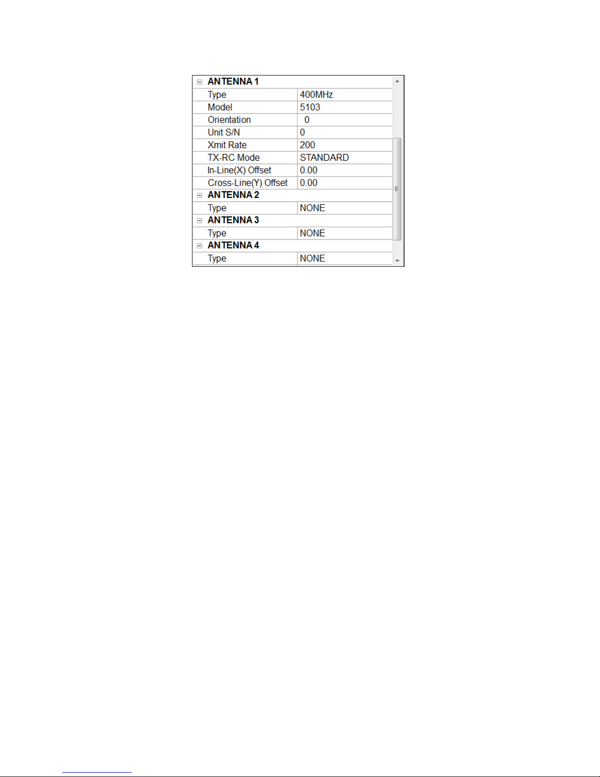
Figure 23: Antenna channel descriptions.
ANTENNA(#)\CHANNEL
The antenna options correspond to the Channel 1-4 inputs on the back of the SIR 30. For each antenna
channel, the User can enter the Antenna Type (Center Frequency), the antenna model number, the antenna
dipole orientation i.e. the dipole polarity axis orientation relative to your profile direction, the antenna
serial number, the transmit rate, the transmit-receive mode and the GPR\GPS antenna distance offset
values.
• The antenna serial number is required if you are using a Model 4105NR 2 GHz Horn with noise
reduction technology. The SIR 30 will use the provided serial number to select the correct Custom
filter file.
• If you selected an antenna model, the SIR 30 will automatically load the maximum poss ible tr a nsmit
rate (abbreviated Xmit Rate) for that antenna. If you would like to set this manually, you must select
CUSTOM from the Antenna Type pull down menu.
Note: In cases where the maximum transmit rate (or PRF) of the antennas is different, the SIR 30 will
use the highest transmit rate that is common to all antennas e.g. If two (2) antennas are connected to
the SIR 30 and one has a maximum PRF of 100 KHz and the other has a maximum PRF of 330 KHz
,the system will use the 100 KHz PRF rate.
• TX-RX Mode allows the User to set the system for Standard transmit\receive mode, Bi-Static
transmit\receive mode (Transmitting from one channel\antenna to another channel\antenna), or Dual
Receiver Mode. (Transmitting from one channel\antenna to another antenna in b-static mode and one
channel in Standard transmit rec eiv e mode).
• In-Line (X) and Cross-Line (Y) Offset are the offset distances from the GPS receiver antenna relative
to the GPR antenna connected to Channel 1
• Clicking Accept will cause the data acquisition mode and antenna(s) to initialize and the display the
Data collection Control Screen.
MN 93-101 Rev E 20
Geophysical Survey Systems, Inc. SIR® 30
Sub-Menu
GPS Signal
Main Menu
Control Bar
Storage
Collect Mode, Channel Number and
Storage
Over Speed
Manual
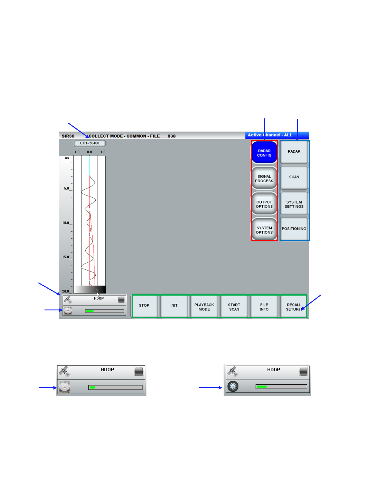
Main Menu Control Screen
Figure 24 below shows the Collect Mode menu. In this example, the system is configured with one
antenna. Selecting the Channel number/Antenna Model button will activate that specific channel display
and a full screen line can display will begin to scroll across the screen. Selecting the Channel
number/Antenna model button again will return you to the channel O-Scope display.
Antenna Model
Quality
Figure 24: Collect Mode menu.
The User will also see the GPS Quality indicator and Storage Space indicator at the lower left corner of the
screen. When data collection is started, the Storage Space indicator will change to the Over Speed
indicator if the system is in the Survey Wheel mode.
Figure 25: GPR Quality Indicator and Storage Space.
MN 93-101 Rev E 21

Grey Scale
Linescan
Channel Number
Main Menu
Control Bar
Sub-Menu
O-Scope Trace display
GPS Signal
Storage
Data
Mode
Geophysical Survey Systems, Inc. SIR® 30
Manual
with red gain function
curve superimposed
Collection
Quality
Figure 26: Collect Mode - One channel active – Time Mode – Channel 1 selected.
We refer to the left hand column of the Setup Controls as the Main Menu (Red) and the right hand column
as the Sub-Menu (Blue). The SIR 30 user interface is structured so that the User moves through the control
settings from top to bottom. When you select one of the Main Menu buttons, it will turn solid blue and the
options in the Sub-Menu will change.
There are four buttons in the Main Menu:
RADAR CONFIG (page 27)
SIGNAL PROCESS (page 41)
OUTPUT OPTIONS (page 47)
SYSTEM OPTIONS (page 56)
Note: If the User is operating with more than one channel and you wish to change the acquisition
parameters of any individual channel, you must activate the specific channel display before making any
parameter changes. If the system is operating in multichannel mode and the User makes a parameter
change with all channels displayed, the parameter change will be applied to all channels (See Figure 27
below). In this mode, the parameters displayed by the system will be those of Channel 1.
MN 93-101 Rev E 22
Geophysical Survey Systems, Inc. SIR® 30
Manual
Figure 27: Collect Mode - Two channels Active Mode.
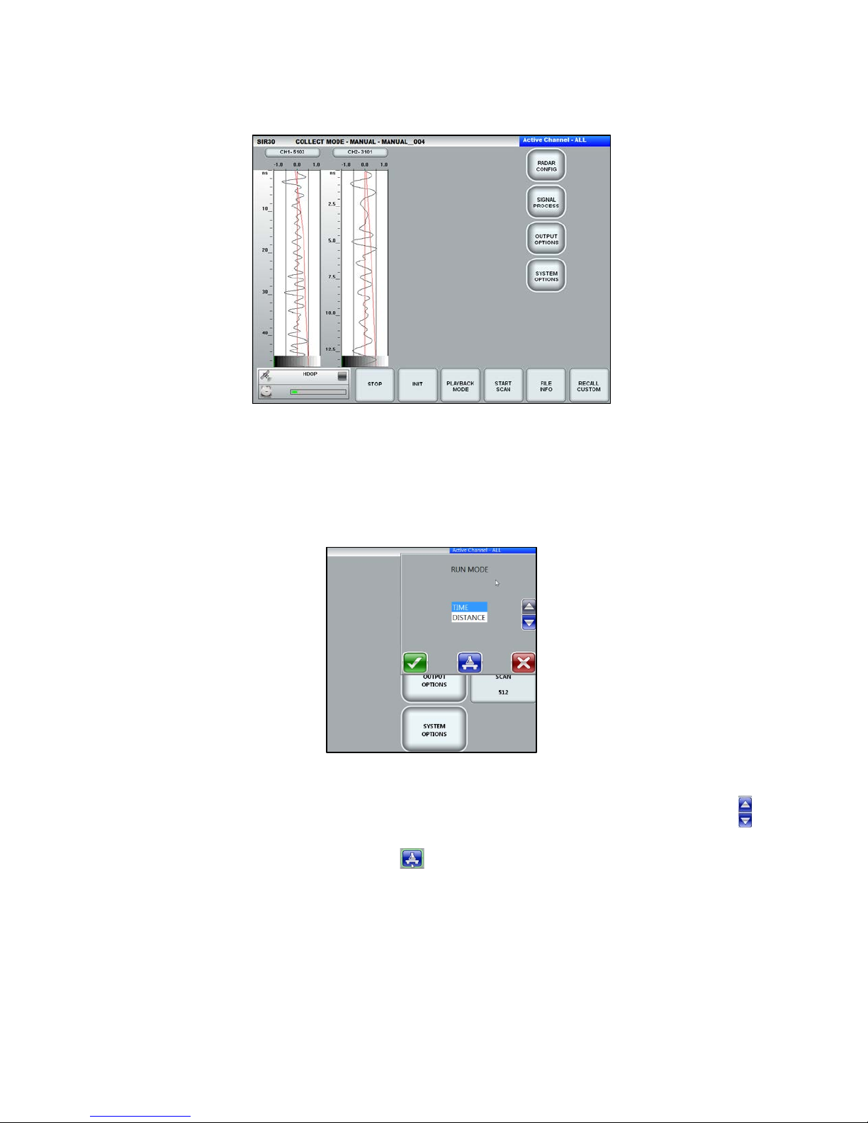
Parameter Selection Dialog
The User may change any variable parameter by selecting the desired menu button with a mouse,
keyboard, or by touching the display (with systems configured with a touch screen display). This will bring
up the parameter selection dialog.
Figure 28: Parameter Selection dialog.
The variables within the parameter selection dialog may be changed by using the Up\Down arrow keys .
The effects that the parameter variable changes have on the data may be evaluated by selecting the Test
function. The Test function is identified by blue Flask icon. Selecting Test will apply the selected
change to the displayed data so that the User may evaluate the effects of the parameter change on the data.
Applying the Test function does not change the value of the parameter.
MN 93-101 Rev E 23
Geophysical Survey Systems, Inc. SIR® 30
Manual
Figure 29: Test function.
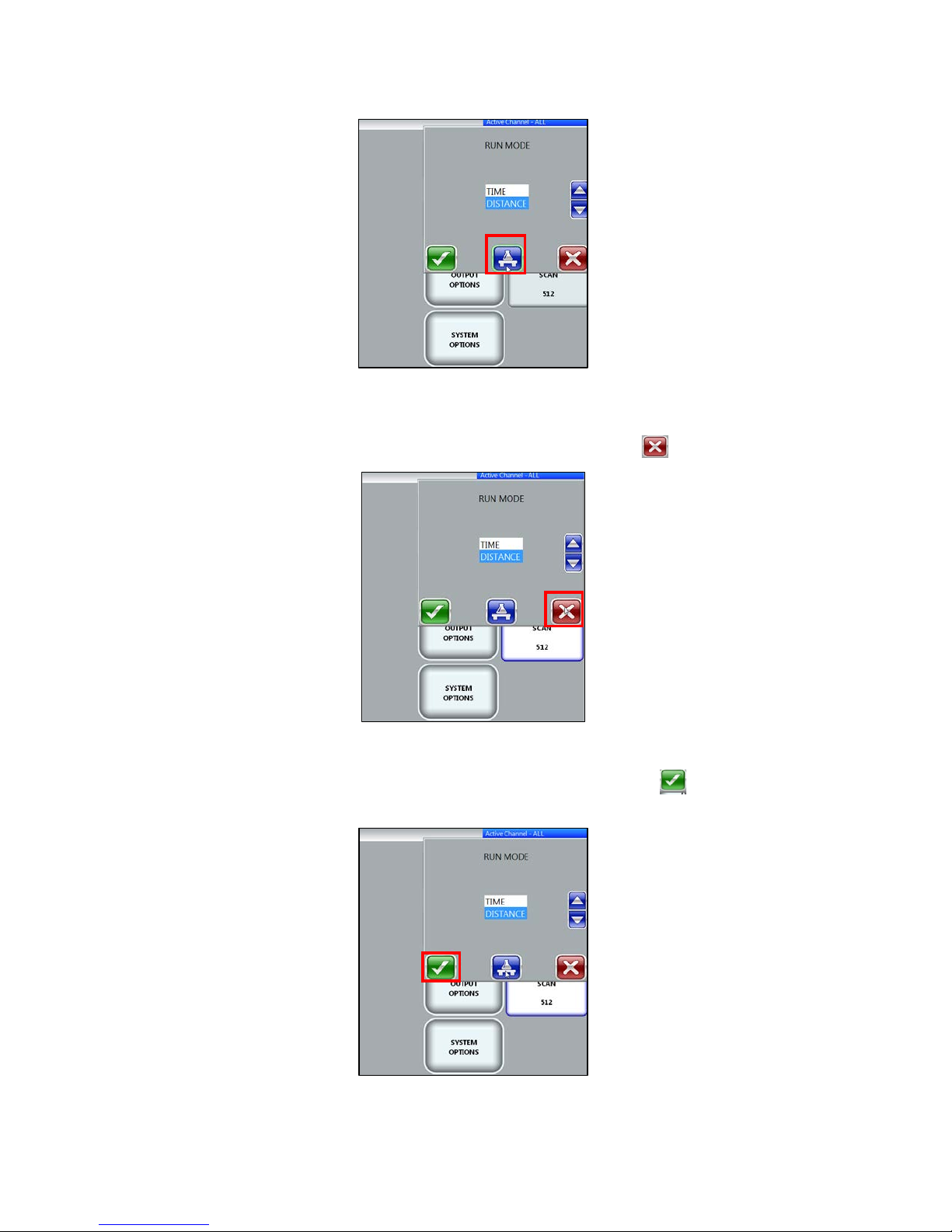
If the User is not satisfied with the parameter change, the User can change the parameter variable again
and re-test or they may cancel the change. To cancel th e change, click the red icon.
Figure 30: Cancel Parameter change.
If the User is satisfied with the parameter change, the User must click the green check icon. This will
apply the changes to the data and close the parameter change dialog.
Figure 31: Accept Parameter change.
MN 93-101 Rev E 24
 Loading...