

GSSI SIR 20 User Manual

Copyright © 2003-2017 Geophysical Survey Systems, Inc.
All rights reserved
including the right of reproduction
in whole or in part in any form
Published by Geophysical Survey Systems, Inc.
40 Simon Street
Nashua, New Hampshire 03060-3075 USA
Printed in the United States
SIR, RADAN and UtilityScan are registered trademarks of Geophysical Survey Systems, Inc.

Geophysical Survey Systems, Inc. SIR® 20
Manual
Limited Warranty, Limitations Of Liability And Restrictions
Geophysical Survey Systems, Inc. hereinafter referred to as GSSI, warrants that for a period of
24 months from the delivery date to the original purchaser this product will be free from defects in
materials and workmanship. EXCEPT FOR THE FOREGOING LIMITED WARRANTY, GSSI
DISCLAIMS ALL WARRANTIES, EXPRESS OR IMPLIED, INCLUDING ANY WARRANTY OF
MERCHANTABILITY OR FITNESS FOR A PARTICULAR PURPOSE. GSSI's obligation is limited to
repairing or replacing parts or equipment which are returned to GSSI, transportation and insurance prepaid, without alteration or further damage, and which in GSSI's judgment, were defective or became
defective during normal use.
GSSI ASSUMES NO LIABILITY FOR ANY DIRECT, INDIRECT, SPECIAL, INCIDENTAL OR
CONSEQUENTIAL DAMAGES OR INJURIES CAUSED BY PROPER OR IMPROPER OPERATION
OF ITS EQUIPMENT, WHETHER OR NOT DEFECTIVE.
Before returning any equipment to GSSI, a Return Material Authorization (RMA) number must be
obtained. Please call the GSSI Customer Service Manager who will assign an RMA number. Be sure to
have the serial number of the unit available.
FCC Class A Compliance
This device complies with Part 15 of the FCC Rules. Operation is subject to the following two
conditions: (1) this device may not cause harmful interference, and (2) this device must accept
any interference received, including interference that may cause undesired operation.
Warning: Changes or modifications to this unit not expressly approved by the party responsible
for compliance could void the user’s authority to operate the equipment.
Note: This equipment has been tested and found to comply with the limits for a Class A digital
device, pursuant to Part 15 of the FCC Rules. These limits are designed to provide reasonable
protection against harmful interference when the equipment is operated in a commercial
environment or residential installation. This equipment generates, uses, and can radiate radio
frequency energy and, if not installed and used in accordance with the introduction manual, may
cause harmful interference to radio communications. However, there is not guarantee that
interference will not occur in a particular installation.
Shielded cables must be used with this unit to ensure compliance with the Class A FCC
limits.
Canadian Emissions Requirements
This Class A digital apparatus complies with Canadian ICES-003.
Cet appareil numerique de la classe A est conforme a la norme NMB-003 du Canada.
Notice
Operation is subject to the following two conditions: (1) this device may not cause interference, and (2)
this device must accept any interference, including interference that may cause undesired operation of the
device.


Geophysical Survey Systems, Inc. SIR® 20
Manual
Table Of Contents
Chapter 1: Introduction ................................................................................................................1
Unpacking Your System ..................................................................................................... 1
General Description ............................................................................................................. 2
Hardware Setup .................................................................................................................... 5
Chapter 2: Setting Up your System for 2D Data Collection .............................................7
System Parameter Setup .................................................................................................... 8
Setting Up your System for 2D Data Collection ...................................................... 10
Data Collection Methods ................................................................................................ 15
Survey Wheel Controlled Collection ........................................................................... 15
Time-Based (Free Run Continuous) Data Collection ............................................. 21
Point Mode Data Collection ........................................................................................... 23
Chapter 3: Setting Up your System for 3D Data Collection .......................................... 27
Tips for Grid Setup ............................................................................................................ 27
The Three Collection Methods ...................................................................................... 28
Setup for Fixed 3D Grid ................................................................................................... 28
Setup for Survey Belt ........................................................................................................ 35
Setup for Survey Wheel ................................................................................................... 42
Chapter 4: Information for StructureScan Users .............................................................. 51
SS Linescan .......................................................................................................................... 51
StructureScan ..................................................................................................................... 57
Structure Scan Optical (Optical Scan) ......................................................................... 62
C-Scan Display of Data and Joining Grids ................................................................. 65
Chapter 5: Using a GPS with your SIR 20 ............................................................................. 67
Attaching a GPS ................................................................................................................. 67
Understanding GPS .......................................................................................................... 68
Using the G30L with the SIR 20 and RADAN 6 ......................................................... 70
Addendum A ....................................................................................................................... 72
Addendum B ....................................................................................................................... 74
Appendix A: SIR 20 System Specifications .......................................................................... 75
Appendix B: The How-To’s of Field Survey ......................................................................... 77
Appendix C: Listing of Antenna Parameters ...................................................................... 83
Appendix D: Glossary of Terms and Suggestions for Further Reading. ................... 91


Geophysical Survey Systems, Inc. SIR® 20
Manual
Chapter 1: Introduction
This manual is designed for both the novice and experienced user of ground penetrating radar. It is
intended as both a reference and a teaching tool and it is recommended that you read the entire manual,
regardless of your level of GPR experience. For information about GPR theory, please see the list of
general geophysics references that can be found in Appendix F.
If you experience operation problems with your system, GSSI Tech Support can be reached 9 am-5 pm
EST, Monday-Friday, at 1-800-524-3011, or at (603) 893-1109 (International). Also be sure to see the
GSSI Support website at support.geophysical.com. Note that you do not need to type in www.
support site has a wealth of information, including software and manual updates, as well as a frequently
asked questions (FAQ) page.
Unpacking Your System
Thank you for purchasing a GSSI SIR® 20 (hereafter referred to as SIR 20). A packing list is included
with your shipment that identifies all of the items that are in your order. You should check your shipment
against the packing list upon receipt of your shipment. If you find an item is missing or was damaged
during the shipment, please call or fax your sales representative immediately so that we can correct the
problem.
The
You may have purchased your SIR 20 as part of a pre-configured system. If you have purchased the
SIR 20 separately, your SIR 20 system contains the following items:
1 - Digital Control Unit MF-20. This is the blue box with the fan on the side and the connectors in the
back.
1 - Panasonic ToughBook
1 - ToughBook CD Drive.
1 - RADAN™ Main and 3D QuickDraw software package. This is pre-loaded on your ToughBook.
1 – DC Adaptor for use with a car cigarette lighter attachment
1 - AC Adaptor
1 - Operation Manual
1 - Transit Case.
Your choice of antenna, cables, and portable battery packs is available for an additional purchase.
Warning: Do not load any additional software on to your SIR 20 laptop. Loading additional software
onto your GPR system may cause system failure. System failure due to the loading of unauthorized
software is not covered by warranty.
®
computer. This will be mounted to the MF-20 box.
MN92-078 Rev F 1
Geophysical Survey Systems, Inc. SIR® 20
Manual
General Description
The SIR 20 is a high-speed, powerful, multi-channel ground penetrating radar system that is ideal for a
wide variety of applications. The various components of the SIR 20 are described below.
External Features
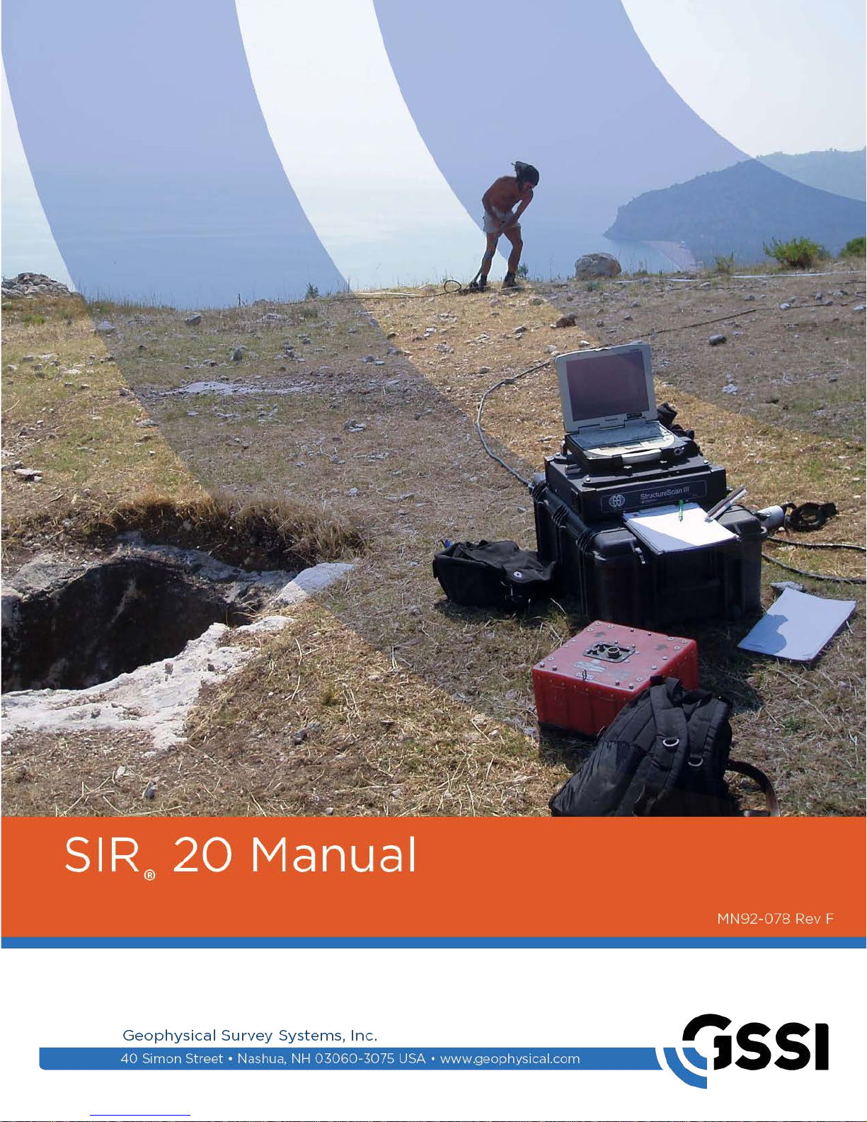
The major external features of the SIR 20 are the MF-20 mainframe, laptop, mounting plate hardware,
network shield and mainframe connector panel. Ther e is also an AC power adaptor and the DC power
adaptor. The DC power adaptor has a cigarette lighter attachment on one end and the square, two-hole
power connector on the other.
Please refer to the image below and note the different external features.
Figure 1: Major external features (May vary depending on Toughbook model).
The SIR 20 is designed to be used in a variety of field configurations. While it is often preferable to leave
the laptop attached to the system as one whole unit, you may sometime wish to separate the computer and
the MF-20 control box. You will first need to loosen the thumbscrews on the front of the mounting plate.
This will allow you to slide the clamp brackets away from the handle of the laptop. You will then remove
the network shield and disconnect the power and network cables. You will then be able to lift the laptop
off of the mounting plate.
Helpful Hints:
tight. Always leave the network shield in place when the laptop is mounted on the MF-20.
MN92-078 Rev F 2
Be sure to periodically check the mounting plate thumbscrews to make sure that they stay
Geophysical Survey Systems, Inc. SIR® 20
Manual
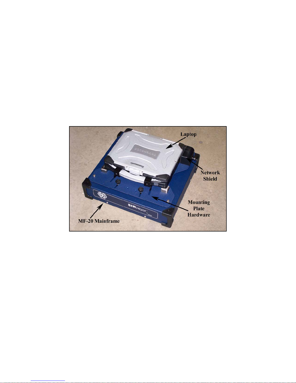
Connector Panel
Turn the SIR 20 around to look at the back of the unit. You will notice that the mounting hardware is
designed to allow you access to the standard computer connectors on the back of the laptop. You can use
these connectors just as you would use them on a regular laptop computer. If you would like to connect a
projector, for example, use the VGA port.
Figure 2: Connectors under network cable shield.
The laptop’s USB port can be accessed opening the protective door at the back of the laptop. The
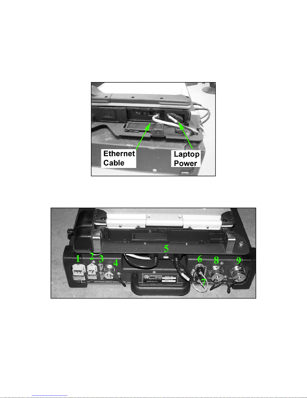
connector panel on the back of the MF-20 is detailed below.
Figure 3: MF-20 connector panel.
1 This port accepts the connector from the Smart Lead/Acid battery (part # FGMOD1218S3). The
metal clip is designed to fit over the battery connector and ensure a tight connection.
2 This port accepts the standard Lead/Acid battery (part # FGMOD1218S2), the AC power supply
connector, or the DC power supply connector. The metal clip is designed to fit over the device
connector and ensure a tight connection.
MN92-078 Rev F 3

Geophysical Survey Systems, Inc. SIR® 20
Manual
3 Indicator lights: The top light will flash amber to indicate that there is good communication
between the laptop and the MF-20. This light will not be lit constantly, but will only flash during
active communication (such as taking data). The bottom light is the MF-20 power light. This will be
lit (green) whenever the MF-20 is on. If you lose power, your laptop will switch to its onboard
battery, but the MF-20 power light will go off.
4 Sync connector: This is reserved for application requiring multiple SIR 20s to be linked together.
This feature is currently unavailable.
5 SIR 20 power converter: The power converter is used to keep the laptop battery charged. If the
SIR 20 is plugged into a power source, there will be a green light on the front of the converter. This
light will be lit even if the SIR 20 is turned off.
Helpful Hint: If your SIR 20 is plugged into a reliable power source but your laptop battery does not
appear to be charging, you should check the two plugs in this converter to make sure there is a good
connection. Also check the 15 amp fuse.
6 Marker connector: This is a 2-pin connector used to attach a remote marker trigger to the system.
The marker trigger would be used to indicate points of interest in the data.
7 Survey wheel connector: This is a 4-pin connector used to attach a survey wheel or DMI (distance
measuring instrument). If you are using your SIR 20 for a pavement mapping application, this is
where you will plug in the lead from your wheel-mounted DMI.
8 Transducer 1 port: This port is hardware channel 1 and accepts a 19 pin GSSI standard control
cable from your antenna. To connect the control cable, line up the 5 indents on the connector with the
5 keys on the male end of the control cable. Then tighten the screw collar on the control cable until
the collar covers the red line on the SIR 20 connector. Only hand-tighten connections. If you are only
using one antenna, connect the antenna to the transducer 1 port.
9 Transducer 2 port: This port is hardware channel 2 and accepts a 19 pin GSSI standard control
cable from your antenna. To connect the control cable, line up the 5 indents on the connector with the
5 keys on the male end of the control cable. Then tighten the screw collar on the control cable until
the collar covers the red line on the SIR 20 connector. Only hand-tighten connections.
MN92-078 Rev F 4
Geophysical Survey Systems, Inc. SIR® 20
Manual
Hardware Setup
To setup your GPR system for data collection, you will need the following items:
• SIR 20
• an antenna
• a control cable
• a power source (AC, battery, or DC)
If you are using a SIR 20 as part of a RoadScan™ system, see Appendix A. If you are using your SIR 20
on a survey cart, please see the survey cart manual for instructions on hardwa re set up.
1 Remove your SIR 20 from the transit case and place on a flat surface. Allow for some airflow around
the cooling fan on the side of the MF-20.
2 Connect your antenna to the SIR 20 with a control cable. Ensure that the connection is hand tight.
3 If you are using a survey wheel, connect the survey wheel lead to the survey port on your antenna
housing.
4 Connect your SIR 20 to your power source.
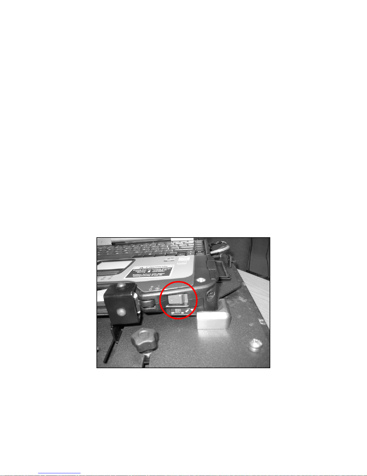
5 Turn on the SIR 20 by turning on the laptop computer. The laptop will boot up and the cooling fan
will come on. To turn the SIR 20 off, shut down the laptop like you would shut down any Windows
computer.
Figure 4: The On Button.
MN92-078 Rev F 5

Geophysical Survey Systems, Inc. SIR® 20
Manual
MN92-078 Rev F 6
Geophysical Survey Systems, Inc. SIR® 20
Manual
Chapter 2: Setting Up your System for
2D Data Collection
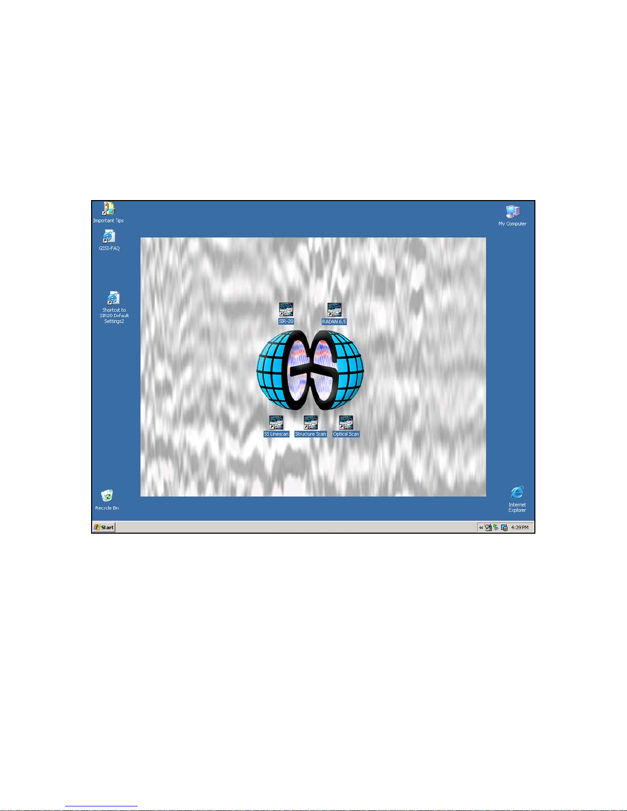
After your SIR 20 boots up, you will see a Windows desktop with a number of shortcuts on it.
A base SIR 20 system includes one shortcut icon that will open the data collection program
(SIR 20) and one icon that will open the data processing package (RADAN).
Figure 5: SIR 20 Desktop (with StructureScan™ Icons).
You will see five additional shortcuts with a GPR profile outline: RADAN, SIR 20, SS Linescan,
Structure Scan, and Optical Scan. RADAN is only for data processing. The other four open separate data
collection programs. SS Linescan, Structure Scan, and Optical Scan are specifically designed for shallow
scanning of concrete structures with very high frequency antennas. Operation of these programs will be
discussed later in Chapter 4. SIR 20 is the general purpose data collection program.
MN92-078 Rev F 7

Geophysical Survey Systems, Inc. SIR® 20
Manual
System Parameter Setup
This section will take you through the initial program setup for data collection.
Create Folders
The SIR 20 is capable of collecting an enormous volume of data. The first important task of the GPR user
is to find some way to keep this data organized. The SIR 20 uses the hard disk of the ToughBook
computer to store data. Before beginning each project, you may wish to create a new folder on the
laptop’s hard disk. This folder can have any name associated with it, so you can name it by date, customer
name, or job number.
Creating a new folder in Windows is easy; just follow the following steps:
1 Click the Start button on the Windows toolbar at the bottom of the screen. This will open a big pop-
up menu.
2 Find the option for My Computer and click it. This will open a window showing any disk driv es th a t
you have installed.
3 Find the Hard Disk Drives section and double-click Local Disk (C:). This will open a window
showing all of the folders that you have stored. You will see six choices at the top of the screen. They
say: File, Edit, View, Favorites, Tools, Help. C lick on F ile.
4 Move the arrow down to New and then over to Folder. Click on Folder. You will see that Windows
creates a new folder on your C: drive. You will need to rename this.
5 Type in a new name and press Enter on the keyboard.
6 Double-click the little picture of the folder that you just made to go inside it. Repeat Steps 4 and 5 to
create a new folder inside of the one you are in. Call th is one Output. We will look at why you need
an output folder later.
7 Now you are done. Go back to the Desktop and double-click the SIR 20 icon. This will open the
SIR 20 program.
Note:
You will see a RADAN splash screen when you open the SIR 20. This is because the SIR 20
program is a module that runs in RADAN. Click anywhere on the screen to make the image disappear.
MN92-078 Rev F 8
Geophysical Survey Systems, Inc. SIR® 20
Manual
Set Program Defaults
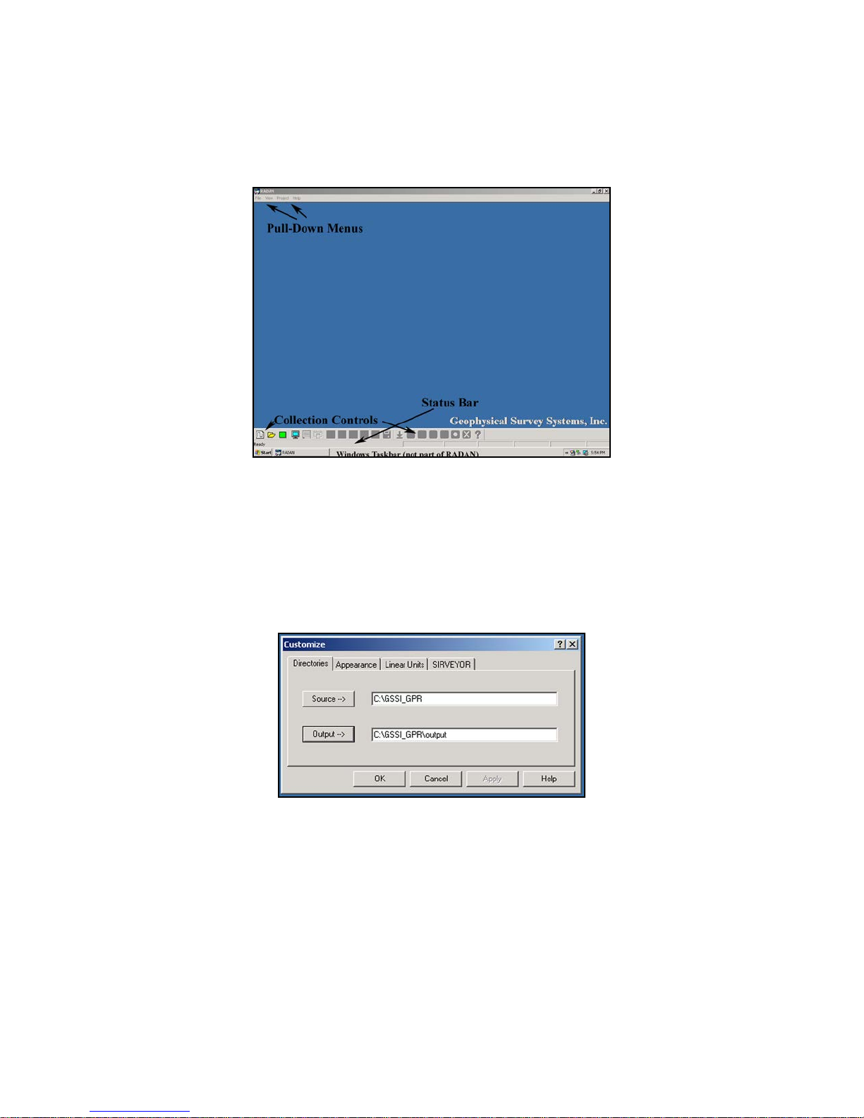
Now you will need to tell RADAN about the folders you created and set some other parameters. Doubleclick the SIR 20 shortcut on the Windows desktop. We will star t fro m the initial RAD A N /SIR 20 screen.
Figure 6: SIR 20 initial screen.
1 Find the View pull-down menu at the top of the screen and click on it. Look for the Status Bar and the
Customize options.
2 Make sure that there is a check next to the Status Bar. If not, move the arrow down to highlight it and
click on it.
3 Next click Customize. You will see a window with four tabs at the top.
Figure 7: Customize window.
4 Directories: Set working directories.
• Click the Source button. You will see a window pop-up with a list of folders that are on your
computer. If you type in a new complete path beginning with C:\ then RADAN will also create a
new folder for you.
• Find the folder that you created in the previous section and click the pict u re o f the little folder to
open it. Then click OK.
• Do the same for the Output folder.
MN92-078 Rev F 9

Geophysical Survey Systems, Inc. SIR® 20
Manual
• We need to have a Source and an Output folder because the SIR 20 will store different parts of
your data in different places. It does this so that parts of data that you don’t want to get
overwritten by accident (like project info files) are protected in the Source folder while the
system stores other files in the Output (like collected and processed data).
5 Appearance: Set your viewing preferences under Appearance.
• This tab controls the look and feel of the software. If you like to see Large Buttons on the screen
for example, make sure that that choice is checked. These changes will take effect the next time
that SIR 20/RADAN is started.
6 Linear Units: This sets your units of measurement and the order of magnitude of those
measurements. Choose whatever you feel is appropriate for your application.
7 SIRVEYOR: If you are using a GPS with your system, click the SIRVEYOR tab to configure the
GPS. Instructions on this can be found in the GPS integration chapter.
8 Click OK once you are satisfied that you have set up the system to your desired parameters.
Setting Up your System for 2D Data Collection
Projects and Profiles: How the SIR 20 Collects Data
The SIR 20 collects data files by using a Project file as a model. The project file is created when you enter
collection parameters. Each time you tell the SIR 20 to collect a new data file, it will examine the
parameters you provided in the project file and collect data with those settings. Let’s first look at the three
main file types that are important in 2D data collection: Project, Data, and Macro files. As you create
these different file types, try to keep a notebook with their names and your job information. That way,
you will know what all of these file types mean when you go to review your work. All of these files will
be stored in the folder that you created in the previous section.
Project Files have the extension *.rpj. Their function is to serve as a list of instructions to the SIR 20 so
that the system knows how to collect your data files and what to name them. The name of each data file is
taken from the name of your project file. For example, if you call you project file Test.rpj, you data files
will be named Test001, Test002, etc. You should keep your project file names as short as possible (less
than 8 characters). RADAN will only use the first eight characters of your project file name for each data
(*.dzt) file name. This can lead to confusion if your project file names are too long.
Data Files have the extension *.dzt. These are your actual radar data profiles. When you open a data file
in RADAN, you are opening a *.dzt file. The data file takes it name and data acquisition parameters from
the project file. These files co ntain a File Header as well. The file header contains all of the acquis it ion
parameters settings used to collect a specific *.dzt file
Macro Files have the extension *
collection. You create the macro file during the project file setup process and the macro file is then
attached to the project file . The SIR 20 will use your project file and your macro file as a list of
instructions to collect your data files. This information is stored in the File Header.
.
cmf. These files contain specific settings that your system needs for
MN92-078 Rev F 10

Geophysical Survey Systems, Inc. SIR® 20
Manual
Working with the Master Project File (Optional)
The SIR 20 incorporates a Master Project collection scheme that is intended to streamline data collection.
It is intended for use in application where all data area collected with common settings. The master
project is created by you just like any other project, but it is saved into the Master Project file in the
SIR 20 program. It is then automatically recalled at the beginning of each collection. Upon recalling the
master project, you will have the opportunity to change its name. This will not re-name the master project
file, but will become the root name of all of the data files that you collect going forward.
To use:
1 Create a data collection project as described in the previous section. Take note of the location where
that project is saved.
2 Minimize or close the SIR 20 collection program and copy that project file and the macro to:
C:\Program File\GSSI\RADANXP\Master Project. Make sure the macro copies a s well. For example,
if you called your project TEST, you will need to copy TEST.RPJ (project file) and TEST.CMF
(macro) to the master project file. You can rename it at this point if you wish, but make sure both files
have exactly the same name.
3 When you wish to use the master project, open the SIR 20 collection program and click the Run
Master Project icon located at the bottom-left of the screen.
4 Enter in a new name if you wish. The data files will be saved to the working directory.
5 Collect data as normal.
The File Header
A file header is an integral part of each data file. It contains all of the radar system acquisition parameters
at the time of data collection. The file header comprises the first 1024 bytes per channel of a *.dzt file.
The primary purpose of the File Header is to record and preserve the data acquisit io n parameters used to
collect the data.
While all of the entries in the Header may seem intimidating at first, after you have worked with GPR
data for some time, you will find yourself gaining a full understanding of all of the different pieces of
information that it contains. Some of this information can be edited after collection to correspond to postprocessing changes or for report generation. In addition, the file header can include field information such
as location, client, date, job number, surface material, or other information useful in characterizing a site.
MN92-078 Rev F 11
Geophysical Survey Systems, Inc. SIR® 20
Manual
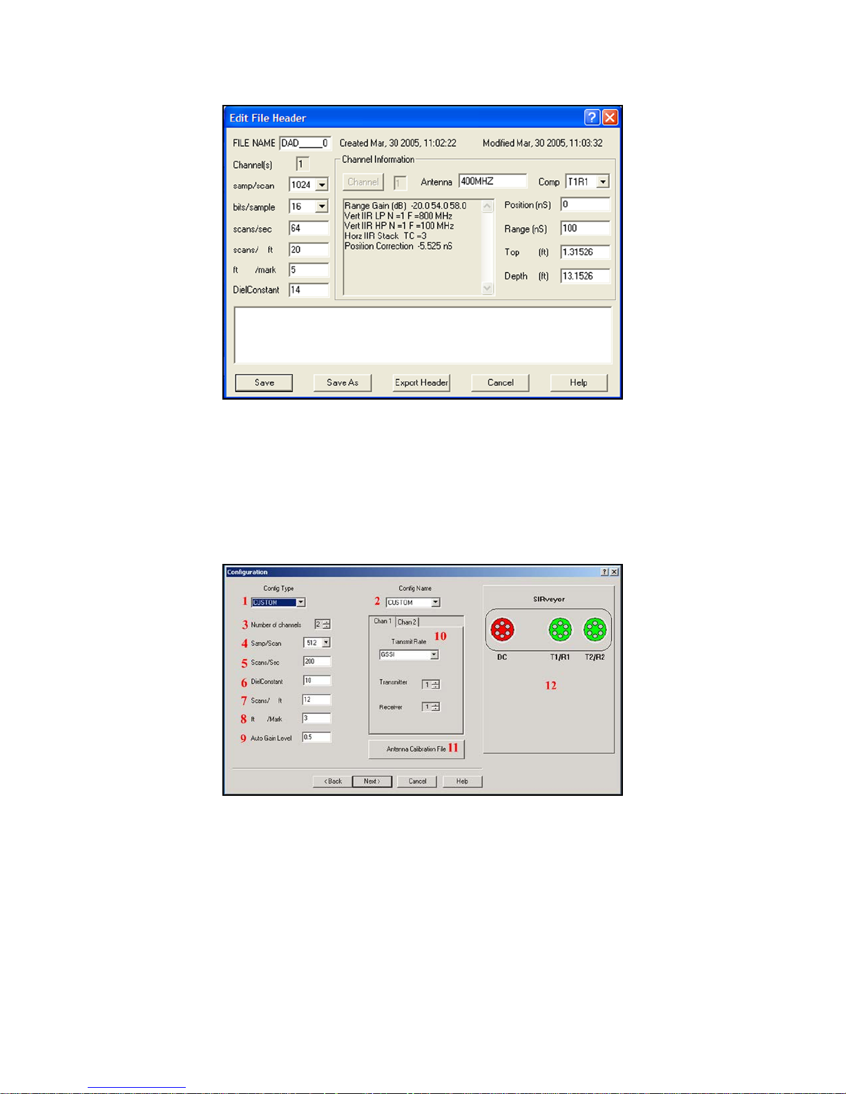
Figure 8: File Header Dialog Box.
File header parameters include: fi le name, antenna frequency, range, transmitted pulse position, channel,
samples/scan, bits/sample, scans/unit, units/mark, dielectric constant, and approximate depth range.
Scans/unit will be English (Imperial) or Metric units depending on what linear units you selected in
View > Customize.
Collection Parameters
Figure 9: The Configuration Window.
Your SIR 20 can be used for many different applications. Because of this, you should have a full
understanding of how different configuration settings should be applied to each type of survey. You will
see the Configuration Window during a new collection project setup, but it is useful to explain these
parameters first.
MN92-078 Rev F 12

Geophysical Survey Systems, Inc. SIR® 20
Manual
1 Config(uration) Type: This allows you to access a number of pre-defined settings for common
applications. These include: structure concrete scanning, utility locating, bridge assessment, highway
survey, and geophysical surveys. If you application fits into one of these broad categories then you
can select one of these for a quick, easy setup.
• If your application is not listed, then you should select Custom window 1 and 2 and set up your
antenna manually. A list of appropriate default settings can be found in the back of this manual.
2 Config(uration) Name: After selecting a Config type in window 1, you can select the antenna that
you are using. This makes for easier setup of antenna-specific parameters such as filter settings and
time range.
• If your antenna is not listed, then you should select Custom in window 1 and 2 and set up your
antenna manually. A list of appropriate default settings can be found in the back of this manual.
3 Number of Channels: The SIR 20 can operate one or two data collection channels simultaneously.
If you want to run two antennas or to use one as a transmitter and the other as a receiver for bi-static
or Common Depth Point (CDP) profiling, you should select Custom in windows 1 and 2 and then
select 2 channels here. You will need to have two similar antennas and two control cables of the same
length if you intend to use two hardware channels for bi-static or CDP data collection. You will
further define the two channels in windows 10 and 12.
4 Samp/Scan: The default sample per scan setting is 512. This is the number of samples per scan that
the SIR 20 will use to digitiz e the t race. This number must be greater than 10 times range/antenna
pulse width to avoid aliasing. Antenna pulse widths are listed in the antenna setup section at the back
of this manual. Sampling densities available are: 128, 256, 512, 1024, and 2048.
5 Scans/Sec: This is the number of individual data scans that your system is collecting every second.
• If you are using the free run (time based) collection mode, then this number, along with the
transmit rate, your survey speed and the type and width of any horizontal filter selected
determines your scan density along your profile.
• If you are collecting data with a survey wheel, then this number, along with the transmit
frequency and scans per unit distance (window 7) determines your maximum survey speed. For
example, if your system is taking 100 scans/sec and you want to collect 10 scans/ft, then the
maximum speed you can go is 10 ft/sec. The maximum scan/sec is automatically calculated by
the SIR 20 and is derived from the relationship between samples/scan and the systems transmit
rate (window 10). This estimated value can be affected by a number of timing parameters. These
effects are seen with higher (greater than 200 KHz) transmit rates.
6 DielConstant: Short for dielectric constant. The range of values for the dielectric constant of
materials (including air and water) are 1-81. This will allow the SIR 20 to display a linear depth scale
as the vertical scale rather than time. If you know the dielectric constant of the material you are
scanning through, you should enter it. Otherwise, leave this set to 1. This parameter has no effect on
the actual depth of the scan.
MN92-078 Rev F 13

Geophysical Survey Systems, Inc. SIR® 20
Manual
7 Scans/ft(m): This is the number of scans per distance unit that you are collecting. If you are using a
survey wheel, then this is the actual number of scans per distance along your profile. This number
should be set as high as practical. The higher the number of scans per unit distance, the larger the data
file size and the slower the data collection speed. If you are collecting free run data, then this number
is for note taking purposes only. If you are collecting survey wheel data and any horizontal filters
and/or static stacking filters are enabled, the filter value will affect the number of scans per unit
distance collected. For example, if you set the scans/ft to 20 and you have a stacking filter set to stack
4 scans, the output file will have 5 scans per foot (20/4), not 20 scans/ft.
8 Ft(m)/Mark: When used in the Survey Wheel mode, the SIR 20 will put a mark into the data at user
specified intervals. A mark is a small vertical line that is superimposed over your data window and is
intended to allow you to easily ‘eyeball’ distance across your profile. The value selected is a matter of
personal preference.
9 Auto Gain Level: Typically set to 0.5. This controls the SIR 20 auto gain servos. When you initialize
the antenna, the SIR 20 runs an algorithm on the received signal and decides how much gain
amplification to apply to the signal. The auto gain level defines how strong the gained signal should
be relative to the recordable dynamic range (+/-32767 for 16-bit data). A value of 0.5 means that the
strongest gained sample in any given gain segment will be 50% of the total dynamic range. If you
believe that you have targets or reflectors with highly variable amplitude and are afraid of clipping,
than you should set this value to 0.25 so that there is ‘more headspace’ in the dynamic range to record
sudden large changes in signal amplitudes.
10 Transmit Rate/Channel Selector: This allows you to set different tran sm it freq uenci es for your
antennas. The correct transmit rates can be found in the antenna parameter section at the back of this
manual. Typical transmit rates for GSSI 51XX series antennas are 100 KHz. Older or lower
frequency antennas may have to be set lower. You can also change the channels that those antennas
are run on. For example, if you have two antennas and would like to transmit on one and receive on
the other, then you can enter these parameters here.
11 Antenna Calibration File: This option is used exclusively for RoadScan work with high frequency
horn antennas. Consult the RoadScan application manual for details.
12 SIRveyor: This is a representation of the connectors on the back of the SIR 20. This allows you to
visually double check that you have the correct antenna plugged into the correct channel port.
MN92-078 Rev F 14
Geophysical Survey Systems, Inc. SIR® 20
Manual
Data Collection Methods
There are three ways that you can collect GPR data: In Survey Wheel mode, i.e. scans per unit distance,
Free Run mode, i.e. scans per second, and Point Mode, i.e. one scan per each discrete antenna position.
Survey wheel data collection means that you have a survey wheel distance encoder, DMI, or a
StructureScan minicart. These devices allow you to collect data at a specific even scan spacing so that
your data is collected with a linear horizontal scale, no matter what speed you are collecting data at. This
is the easiest, most accurate way to collect data and is recommended for most users. This mode of data
collection is required for the RADAN Migration routine and other signal processing functions to operate
correctly.
Free run data is collected without the benefit of a survey wheel. Your data does not have position
information unless you are also using a GPS. The SIR 20 will collect a certain number of scans per
second and it is up to you to move your antenna over your survey surface at a constant rate. If you collect
free run data you should lay out a tape measure along your survey line and click your marker button
whenever you antenna passes a measured grid point (e.g. every 5 feet). This will allow you to determine
the approximate location of reflectors in your data. You can perform distance normalization in RADAN
on this type of data later to convert the horizontal scale to an approximate linear scale. See the RADAN
User’s Manual for details on distance normalization.
Point mode data is collected one scan at a time with the antenna placed at a discrete location along a
profile line. After a scan is collected, the antenna is picked up and moved to a new location for the next
scan. This is commonly done with large, low frequency antennas, in areas with rough surface conditions
or rugged terrain, or when collecting a common mid-point stack with tw o an ten n as .
Now let’s look at how to set up for each of these modes.
Survey Wheel Controlled Collection
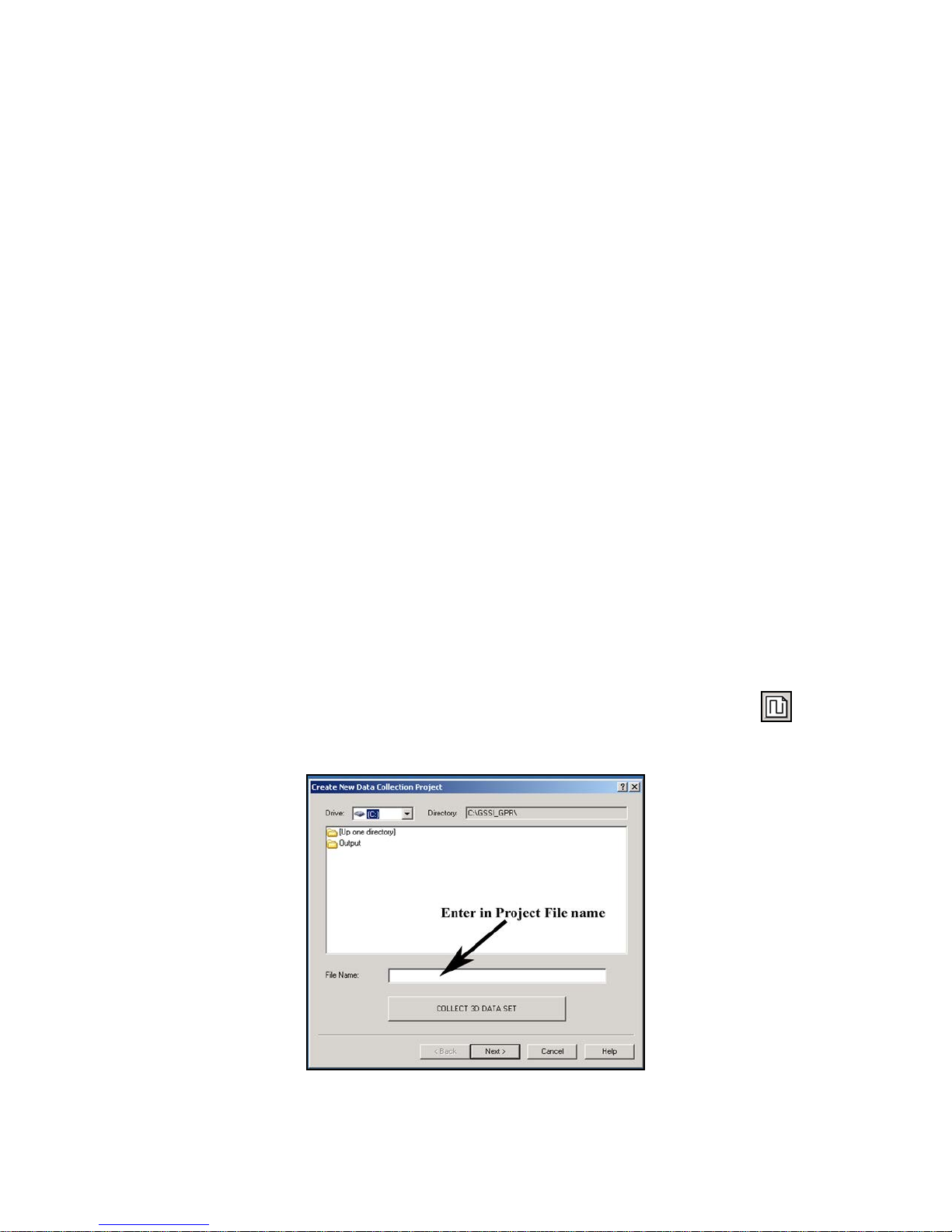
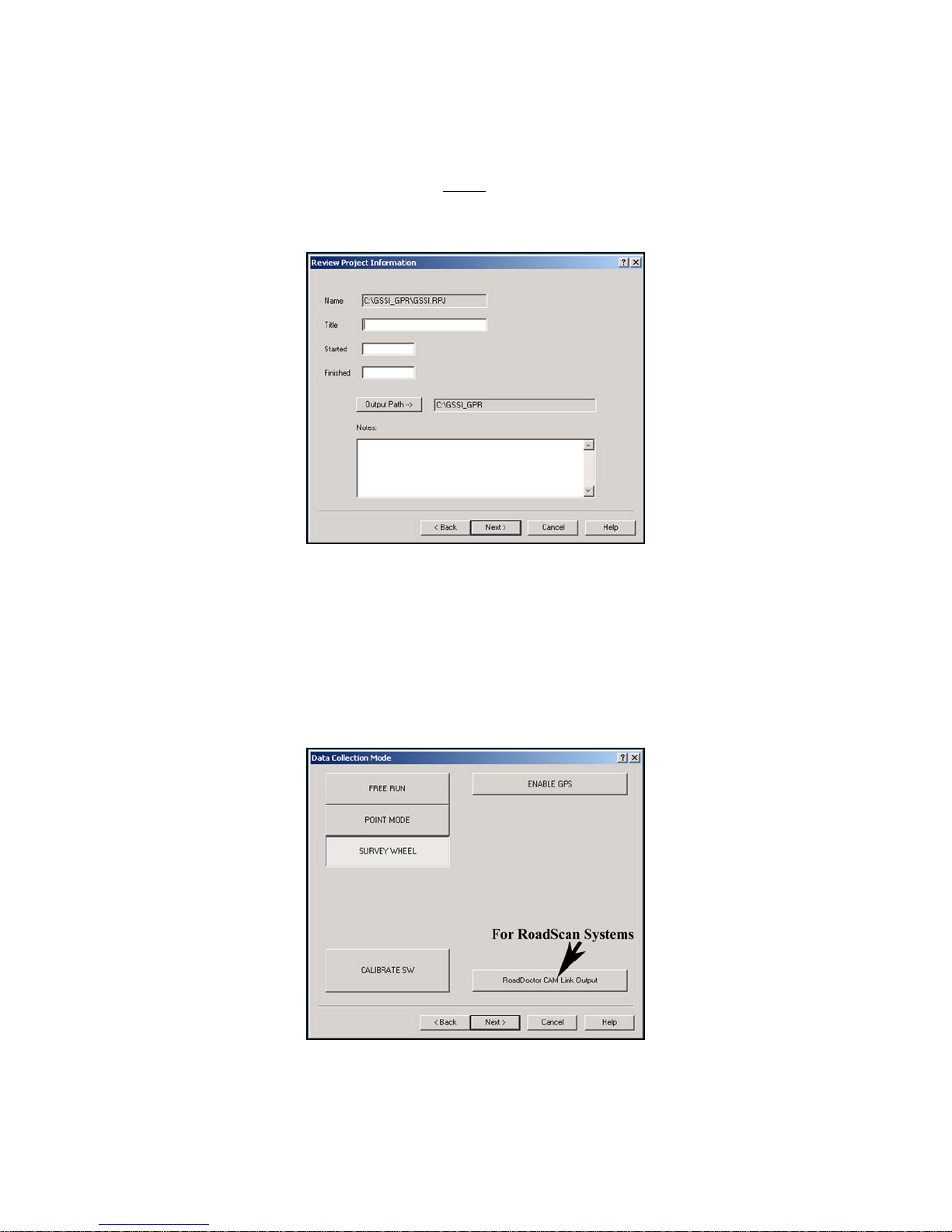
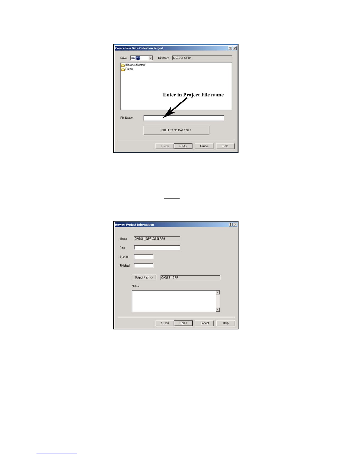
1 Create a new collection project by going to File > New or clicking the New Project button on the
collection controls bar. This will open a window with the heading Create New Data Collection
Project (Figure 10).
MN92-078 Rev F 15
Figure 10: Project File Name box.
Geophysical Survey Systems, Inc. SIR® 20
Manual
2 Enter a project file name in the white box that is labeled File Name: Remember to keep the name less
than 8 characters. Alphanumeric values are acceptable. Do not use any symbols.
• We are only collecting 2D data now, so do not click the button that says Collect 3D Data Set.
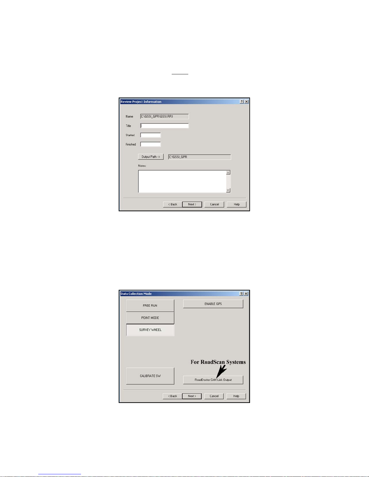
• Click Next >. This will open a new window with the heading Review Project Information (Figure
11).
Figure 11: Project Information dialog box.
3 Enter information to describe your project area. You can give the project a Title, Start/Finish time and
add Notes.
• Note the gray button for Output Path. This is the location where the SIR 20 will store your data
files. This location was set by you in View > Customize.
• All data entry on this screen is optional. If you do not wish to add notes, click Next >.
A window will open with the heading Data Collection Mode (Figure 12).
MN92-078 Rev F 16
Figure 12: Data Collection Mode window.
Geophysical Survey Systems, Inc. SIR® 20
Manual
4 This window provides you with a choice of the three ways you can collect radar data. We will discuss
Free Run and Point Mode later, but for now click the Survey Wheel button.
• Notice the button for Enable GPS. You can collect GPS data along with your survey wheel, free
run, or point data. See the section on using a GPS for details on setup.
• After you click Survey Wheel, you should see a button for Calibrate SW. Click on it.
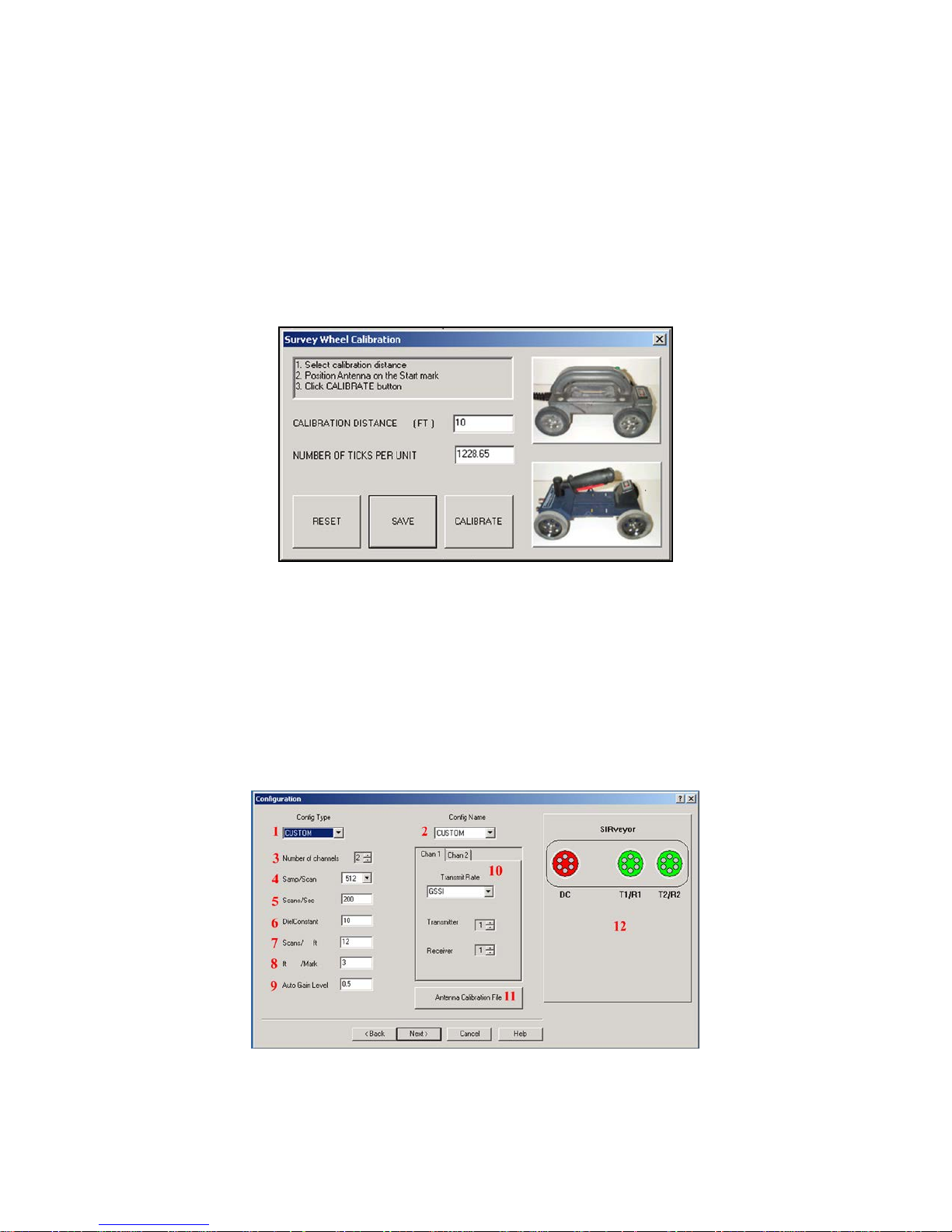
5 You will see a window pop up with the heading Survey Wheel Calibration (Figure 13). This is where
you enable the specific survey wheel device you are using with the SIR 20 and determine how many
internal ‘ticks’ per selected unit of distance.
Figure 13: Survey Wheel Calibration dialog box.
• If you have a StructureScan minicart, click on the image of the cart that you have.
• If you have an Optical cart, click the imag e of the blue minicart.
• If you have a different survey wheel device than the ones pictured, then you must calibrate your
survey wheel.
• Once calibrated, click Save > Next >. This will open a window with the heading Configuration
(Figure 14). You must calibrate your survey wheel. Failure to do so will r esult in an incorrect
horizontal scale on your profiles.
MN92-078 Rev F 17
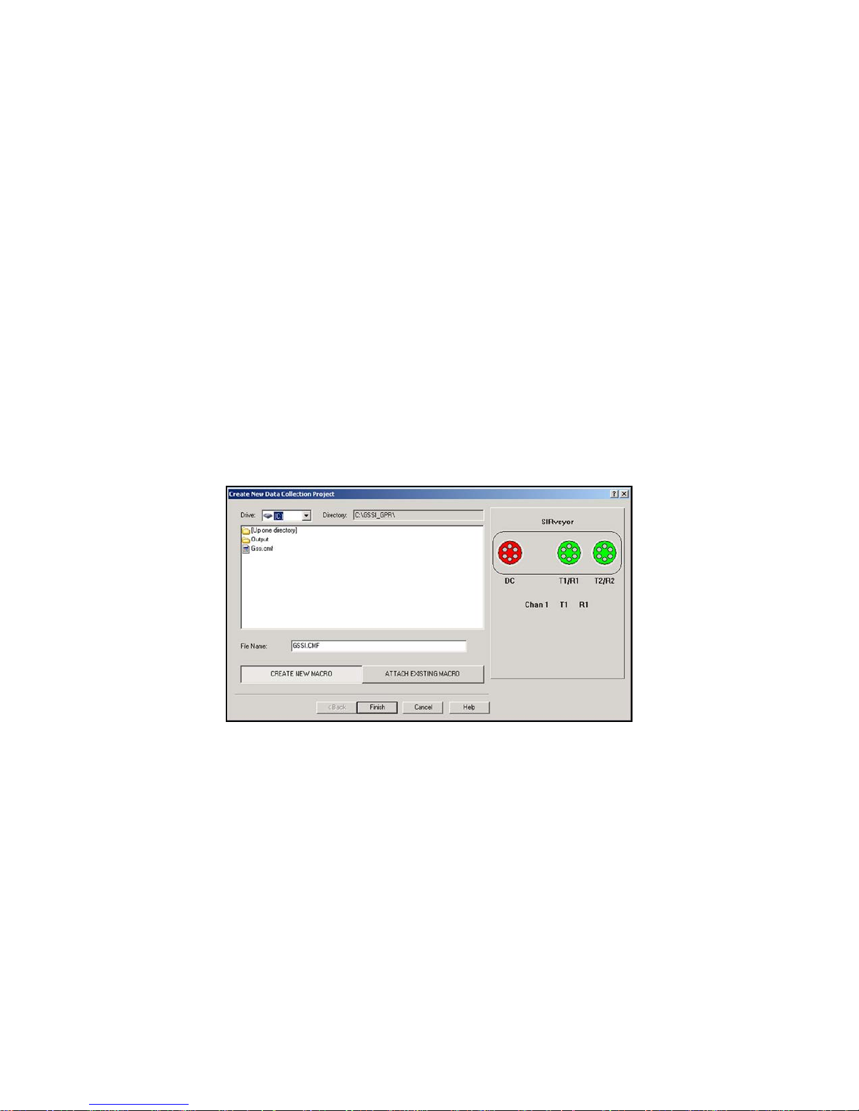
Figure 14: Configuration window.
Geophysical Survey Systems, Inc. SIR® 20
Manual
6 This screen enables you to select/change your data acquisition parameters. For most applications the
default settings are adequate. To access settings for different applications click the small arrow in the
Config Type (1) option.
• You will see a broad list of application categories. Choose the one that best describes your
application.
• For example if you are scanning a concrete slab to find reinforcing bars, choose CONCRETE.
Then choose your antenna type under Config Name (2). An X after the configuration name is
used to denote use of an antenna that has its dipoles oriented perpendicular to the normal survey
direction. Common data collection parameters will be automatically set.
7 Check to make sure that Scans/ft (7) is adequate for your application. Generally, the more scans per
unit that you collect, the slower your collection speed, the larger your data file and the more stretched
your file will appear. When you are finished, click Next >.
8 The next window (Figure 15) will ask you to either create a new macro, or attach one that you have
already created. A macro is nothing more than a saved list of data collection param eters. Th ese
parameters include: filters, time range and gain settings. These parameters will vary from job to job,
so it is possible that you will have many different macros for different survey objectives. Common
parameters for your antenna will be selected automatically based on the Config Type and Config
Name that you chose in Step 6.
Figure 15: Attach a Macro or Create a New One.
• There are no pre-saved macros on the system, so if you are using your SIR 20 for the first time
you will need to create one. Click the button for Create New Macro and click Finish. The antenna
will initialize, you will see a clock counting a few seconds and then the following window will
pop-up:
MN92-078 Rev F 18
Geophysical Survey Systems, Inc. SIR® 20
Manual
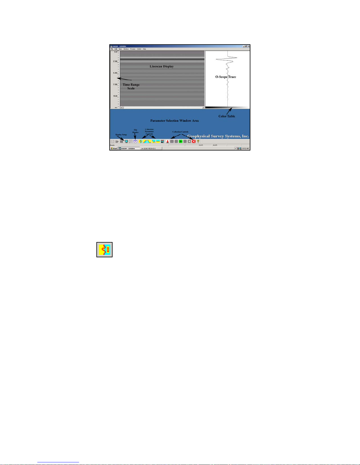
Figure 16: The Setup Screen.
9 This window will allow you to further customize your data acquisition parameters. The window is
divided into two main areas.
• The top 2/3 of the window shows the data display as O-scope and Linescan.
• The bottom 1/3 is reserved for parameter selection pop-up windows. These parameter selection
windows can be accessed by clicking on one of the blue and yellow acquisition parameter
controls at the bottom of the screen.
• You can also check the file header by clicking on the File Header icon.
Position/Range
The first collection parameter button is for Position/Range. This controls the length of the time (in
nanoseconds) that the system will acquire data. The default vertical scale is two-way travel time. The
larger the value that you set for time range, the deeper your SIR 20 will record data. This (generally)
translates to scanning deeper, however, total depth of penetration is a function of both the conductivity
’
(
σ
) and permittivity (ε’) of the media, so the range and depth are not directly equivalent.
The Auto Position Servo and Position correction control enable the user to adjust the direct coupling
pulse (i.e., the transmitted pulse) of the antenna to ‘zero’ time, or to adjust the direct coupling pulse up or
down in the selected time range window. You will note that with the auto position servo ‘ON’ the
transmitted pulse is set several nano secon ds b elow the t op of the O-scope display. The Auto Position
Servo automatically sets the transmitted pulse ‘down’ in the time range window approximately 10% of
the value entered for the range e.g. if the time range is set at 50 ns, the transmitted pulse will be set 5 ns
below ‘zero’. This is done to insure that the entire transmitted pulse is recorded.
If this function is inadvertently turned off during system configuration, the transmitted pulse (zero time)
may not be present in the time range window. If this occurs, the data will be useless as you will have no
zero time reference form which to measure time/depth.
GSSI recommends that you leave the Auto Position servo ON until you are familiar with the effects of
moving the signal up or down in the time range window. Please note that the ‘zero’ time on the SIR 20 is
indicated by the value of 100. This value is arbitrary and has to do with the delay time of transmit and
receive signals within the electronics of the system. This value does NOT affect the stored value of the
range.
MN92-078 Rev F 19
Geophysical Survey Systems, Inc. SIR® 20
Manual
Gain
The second button controls the Time-Variable-Gain (TVG). Gain is signal amplification used to
compensate for the natural effects of signal attenuation. As the transmitted signal passes through a
material, it will weaken (attenuate) as the material absorbs some signal. Gain amplifies that signal after it
is received to compensate for signal losses and make weaker reflectors easier to see. No additional energy
is sent out of the antenna.
The Gain function operates at a number of linearly distributed points along the time range. The Auto Gain
Servo automatically sets the gain of the system based upon the received signal from the antenna at the
point where the antenna is located when the servo is enabled. At large sites it may be necessary to briefly
scan the site to decide if the Auto Gain Servo gain values are too high or too low.
In either case, you should adjust the gains manually. You cannot set the exact time of a gain point;
however, you can manipulate the number of gain points so as to ‘position’ a gain point near a particular
time range (or a particular reflector). You can then adjust the amount of gain applied.
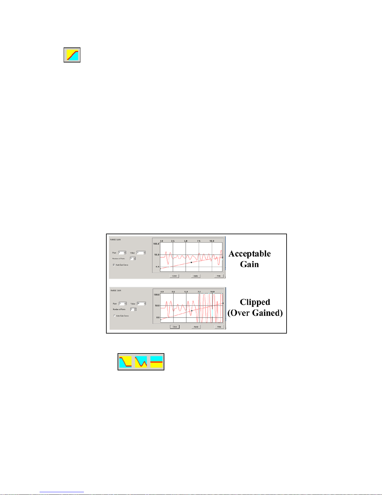
Gain should never decrease with depth. Each successive gain point should be greater than or equal to the
previous. Be careful not to apply too much gain. This will lead to a phenomenon known as ‘clipping’.
Clipping will limit the data and will cause you to lose valuable information and make it much more
difficult to identify targets in the data. In addition, RADAN functions such as vertica l and horizontal
filtering, FFT filtering, Spectrum transformation and Hilbert envelope processing will not operate
correctly on the data. If you prefer to leave the gain setting up to the SIR 20, make sure that Auto Gain
Servo is enabled.
Figure 17: Example of clipped versus acceptable data.
Filters and Stacking
The next three buttons control filters and stack ing. These are useful for removing both high and low
frequency noises, as well as horizontal noise known as ‘ring-down’ in the data. Horizontal noise is an
artifact caused by variability in antenna coupling or high surface permittivity/ conductivity. A background
removal filter of suitable length will remove these artifacts.
Many of the filter parameters are antenna-specific and are set automatically for the antenna that you chose
in Step 6. If you are using an antenna other than one listed in the default configuration you should alter
the filter settings for the antenna being used. Consult your antenna documentation for correct settings.
GSSI recommends that inexperienced users accept the default settings.
MN92-078 Rev F 20
Geophysical Survey Systems, Inc. SIR® 20
Manual
Any changes you make to the collection parameters are automatically stored in the macro file. After you
are satisfied with the collection parameters, click the green arrow
profile will resize to fit the whole screen.
to begin collection. The Linescan
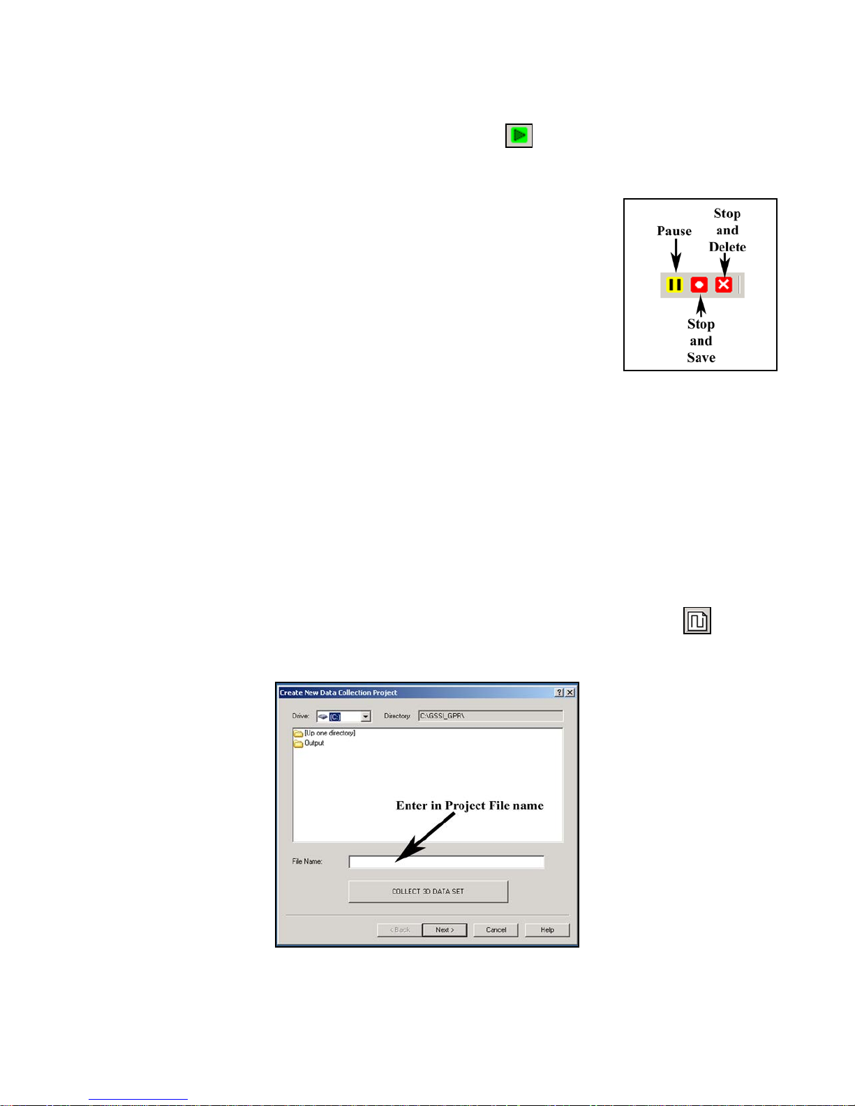
During Collection
• During survey wheel collection, you can stop moving at any time. Since the
survey wheel controls data collection, if the wheel is not turning, the SIR 20
is in pause mode.
• Clicking the marker button on your antenna tow handle or the down arrow
on the laptop keyboard will put a mark (dashed line) in the data. This is
useful for marking permanent surface features of interest on your survey
surface.
• You can end the survey by clicking the appropriate button on the collection
toolbar. You can also close (and save automatically) the file by holding down the antenna tow
handle marker button for 5 seconds.
• To collect another profile with the same settings, click the Run Project button (green square).
Time-Based (Free Run Continuous) Data Collection
The setup procedure for a time-based collection is very similar to a survey wheel-controlled collection.
The SIR 20 is configured to collect a certain number of scans per second and it will be up to the operator
to move the antenna over the survey surface at a reasonable speed. If you move slowly you will collect a
large number of scans per distance, and if you move your antenna rapidly you will collect a small number
of scans per distance.
1 Create a new collection project by going to File > New or clicking the New Project button on the
collection controls bar. This will open a window with the heading Create New Data Collection
Project (Figure 18).
Figure 18: Project File Name box.
MN92-078 Rev F 21
Geophysical Survey Systems, Inc. SIR® 20
Manual
2 Enter a project file name in the white box that is labeled File Name: Remember to keep the name less
than 8 characters. Alphanumeric values are acceptable. Do not use any symbols.
• We are only collecting 2D data now, so do not click the button that says Collect 3D Data Set.
• Click Next >. This will open a new window with the heading Review Project Information
(Figure 19).
Figure 19: Project Information dialog box.
3 Enter information to describe your project area. You can give the project a Title, Start/Finish time and
add Notes.
• Note the gray button for Output Path. This is the location where the SIR 20 will store your data
files. This location was set by you in View > Customize.
• All data entry on this screen is optional. If you do not wish to add notes, click Next >.
A window will open with the heading Data Collection Mode (Figure 20).
MN92-078 Rev F 22
Figure 20: Data Collection Mode.
Geophysical Survey Systems, Inc. SIR® 20
Manual
4 Even though the Configuration Window will show options for Scans/Ft, that parameter has no affect
on time-based data collection. The most important collection parameter is Scans/Sec. This is the
number of scans that your SIR 20 will record every second. The most common method for
determining the correct number is to figure out how many scans per unit distance you want and
compare that to a comfortable walking pace. For example, 12 scans per foot is desired and the
operator will walk at 3 feet per second. The Scans/sec should then be set at 36.
5 Once you have made changes to the collection parameters, follow Steps 8 and 9 of the Survey Wheel
Controlled Collection setup.
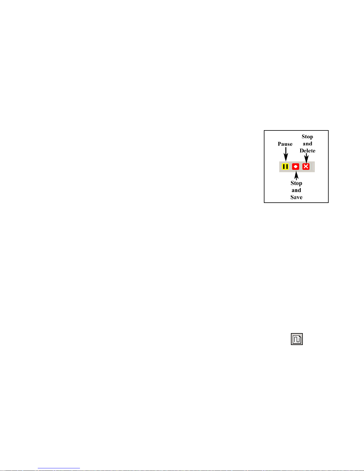
During Collection
• During time-based collection, you can stop moving at any time, but the
SIR 20 will continue to collect data. You can interrupt data collection by
clicking the pause button on the collection toolbar, or by holding down the
marker button on the antenna tow handle for at least 3, but no more than 5
seconds.
• Clicking the marker button on your antenna tow handle or the down arrow
on the laptop keyboard will put a mark (dashed line) in the data. This is
useful for noting features of interest at your survey site and for marking the
linear distance surveyed.
• You can end the survey by clicking the appropriate button on the collection toolbar. You can also
close and save the file by holding down the antenna tow handle marker button for 5 seconds.
• To collect another profile with the same settings, click the Run Project button (green square).
Point Mode Data Collection
This data collection mode is very similar to survey wheel and time-based collection. Point data mode
collection is usually performed with large, low frequency antennas or with two similar antennas in a bistatic configuration. W hen t wo antennas are used, one a cts as a transm itter and on e as a receiver .
Typically point data is collected at discrete stations spaced at a constant separation which will produce a
file with a linear horizontal scale. Care must be taken when selecting the scan spacing. If too small a
number of traces per unit distance are collected, the profile will be under-sampled and you could miss
targets of interest. If too large a number of traces are selected, the data file will be ov er-sampled. This will
generate a very large file and can significantly increase in the time to collect the file.
1 Create a new collection project by going to File > New or clicking the New Project button on the
collection controls bar. This will open a window with the heading Create New Data Collection
Project (Figure 21).
MN92-078 Rev F 23
Geophysical Survey Systems, Inc. SIR® 20
Manual
Figure 21: Project File Name box.
2 Enter a project file name in the white box that is labeled File Name: Remember to keep the name less
than 8 characters. Alphanumeric values are acceptable. Do not use any symbols.
• We are only collecting 2D data now, so do not click the button that says Collect 3D Data Set.
• Click Next >. This will open a new window with the heading Review Project Information
(Figure 22).
Figure 22: Project Information dialog box.
3 Enter information to describe your project area. You can give the project a Title, Start/Finish time and
add Notes.
• Note the gray button for Output Path. This is the location where the SIR 20 will store your data
files. This location was set by you in View > Customize.
• All data entry on this screen is optional. If you do not wish to add notes, click Next >.
A window will open with the heading Data Collection Mode (Figure 23).
MN92-078 Rev F 24
 Loading...