

GSSI Profiler EMP-400 User Manual


Copyright © 2008-2015 Geophysical Survey Systems, Inc.
All rights reserved
including the right of reproduction
in whole or in part in any form
Published by Geophysical Survey Systems, Inc.
40 Simon Street
Nashua, New Hampshire 03060-3075 USA
Printed in the United States
SIR, RADAN and UtilityScan are registered trademarks of Geophysical Survey Systems, Inc.
Geophysical Survey Systems, Inc. hereinafter referred to as GSSI, warrants that for a period of
24 months from the delivery date to the original purchaser this will be free from defects in materials and
workmanship. EXCEPT FOR THE FOREGOING LIMITED WARRANTY, GSSI DISCLAIMS ALL
WARRANTIES, EXPRESS OR IMPLIED, INCLUDING ANY WARRANTY OF
MERCHANTABILITY OR FITNESS FOR A
PARTICULAR PURPOSE. GSSI's obligation is limited to repairing or replacing parts or equipment
which are returned to GSSI, transportation and insurance pre-paid, without alteration or further damage,
and which in GSSI's judgment, were defective or became defective during normal use.
GSSI ASSUMES NO LIABILITY FOR ANY DIRECT, INDIRECT, SPECIAL, INCIDENTAL OR
CONSEQUENTIAL DAMAGES OR INJURIES CAUSED BY PROPER OR IMPROPER OPERATION
OF ITS EQUIPMENT, WHETHER OR NOT DEFECTIVE.
Before returning any equipment to GSSI, a Return Material Authorization (RMA) number must be
obtained. Please call the GSSI Customer Service Manager who will assign an RMA number. Be sure to
have the serial number of the unit available
This device complies with Part 15 of the FCC Rules. Operation is subject to the following two conditions:
(1) this device may not cause harmful interference, and (2) this device must accept any interference
received, including interference that may cause undesired operation.
Warning: Changes or modifications to this unit not expressly approved by the party responsible for
compliance could void the user’s authority to operate the equipment.
Note: This equipment has been tested and found to comply with the limits for a Class B digital device,
pursuant to Part 15 of the FCC Rules. These limits are designed to provide reasonable protection against
harmful interference when the equipment is operated in a commercial environment or residential
installation. This equipment generates, uses, and can radiate radio frequency energy and, if not installed
and used in accordance with the introduction manual, may cause harmful interference to radio
communications. However, there is no guarantee that interference will not occur in a particular
installation.
Shielded cables must be used with this unit to ensure compliance with the Class B FCC limits.
This Class B digital apparatus complies with Canadian ICES-003.
Cet appareil numerique de la classe A est conforme a la norme NMB-003 du Canada.
The Profiler EMP-400 has been certified to meet the requirements of the following European standards:
EN61326:1997, A1:1998, A2:2001


This manual is provided as an operational reference tool. It is highly recommended that the User read the
entire manual regardless of your level of experience with electromagnetic induction instruments.
Appendix C is a summary of the basic steps in conducting an EM survey. For additional information on
EM theory and applications please review the list of references, which can be found in Appendix E.
Thank you for purchasing a GSSI Profiler™ EMP-400 electromagnetic induction (EM) instrument,
hereinafter referred to as the Profiler. A packing list was included with your shipment which identifies all
of the items that are in your order. If you find that an item is missing or damaged during shipment, please
call or fax your sales representative immediately so that GSSI can take steps to correct the problem.
Your EMP-400 system (Standard Configuration) includes the following items:
1 – Profiler EMP-400 digital electromagnetic induction instrument
1 – Low carry handle and mounting clamps
1 – Hip height padded shoulder carrying strap and mounting straps
1 – EMP-400/Recon-400 PDA mounting bracket and clamp
1 – TDS Recon PDA with integrated Bluetooth service and WAAS GPS module
1 – AC rechargeable power boot module for Recon-400 PDA
1 –120 V AC re-charger for Recon-400 power boot module
(See PDA manual for Input/Output specifications for International AC charger)
1 – Battery charger for EMP-400 Li-Ion battery
1 - AC power cord for AC battery charger power supply
2 – Re-chargeable Li-Ion batteries for EMP-400
1 – PDA stylus pen and lanyard
1 – USB data transfer cable
1 – Spare stylus pen
1 – Package of PDA screen protectors (10 count)
1 – Recon-400 hand strap
1 – User’s Manual
1 – User’s CD containing the Profiler EMP-400 backup calibration files,
Geometrics MagMap2000 software and a *.PDF copy of the User’s Manual,
the Profiler File Transfer Utility Program and the MagMap 2000 manual
1 – TDS Recon Getting Started Guide
1 – TDS Recon Companion CD
1 – OEM copy of Microsoft Windows Mobile 2003 software for Pocket PC’s

Electromagnetic induction instruments are used for many different types of geologic, engineering and
environmental investigations. These include shallow soils mapping, soil-salinity mapping, ground water
investigations, the detection and delineation of waste pits and associated subsurface contaminants from
acids, salts or volatile organic contaminants (VOC’s). They have also been used extensively for the
detection of conductive geologic media such as clays and ferrous mineral deposits, as well as the
detection of resistive geologic materials such as sand and gravel deposits. In addition, the systems are
used for near-surface archaeological investigations, the detection of buried structures such as building
foundations, as well as for the detection of buried metallic objects such as drums, tanks, large diameter
utilities and other non-descript metallic objects.
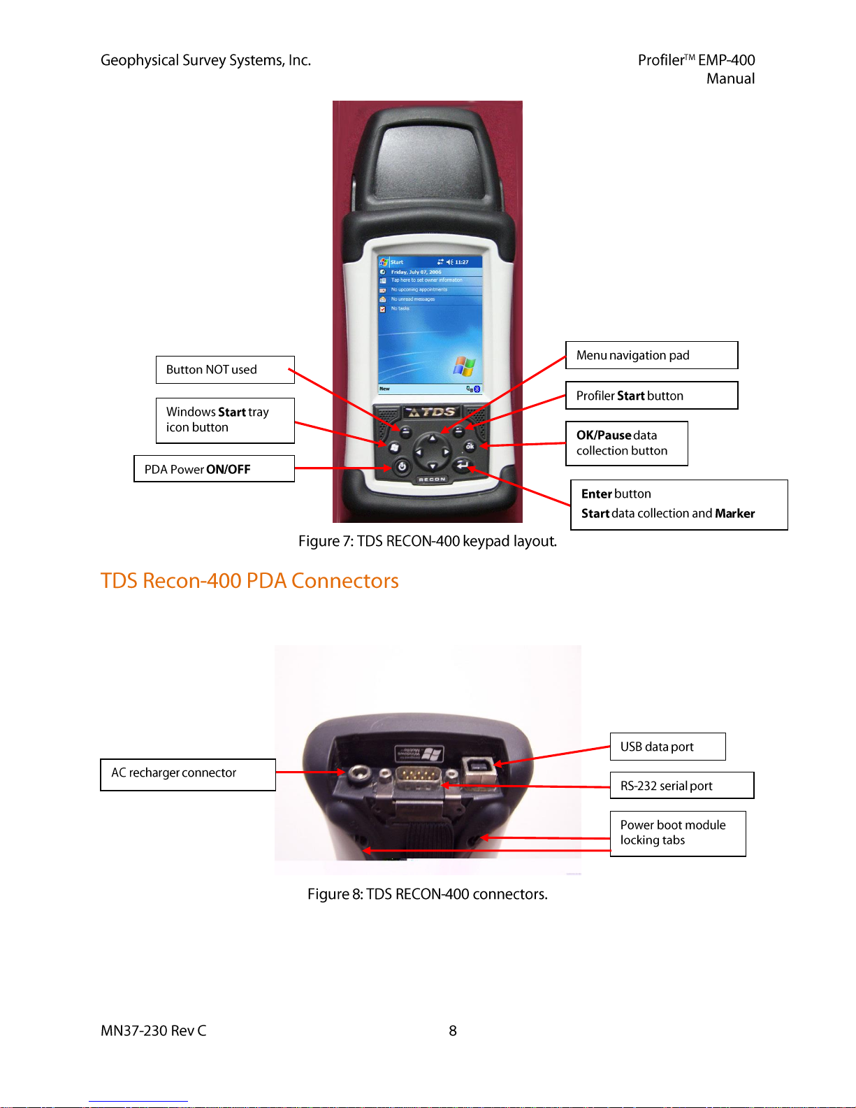
The major system components are the Profiler, the Profiler battery pack and the TDS Recon-400 PDA.
These are illustrated in Figures 1 through Figure 11.
The Profiler is a portable, digital multi-frequency electromagnetic induction sensor. The User can collect
from one (1) to three (3) frequencies simultaneously. The system bandwidth extends from 1 KHz to
16 KHz, in 1 KHz steps. The system’s primary data output is the In-Phase and Quadrature components of
the mutual coupling field ratio of the transmitted field to the induced field in parts per million (PPM) at
all frequencies, and the apparent conductivity (a) at 15 kHz. The magnitude of the In-Phase and
Quadrature components of the induced secondary field, as well as the apparent conductivity are stored for
each reading along with a time stamp and user supplied survey grid information. GPS data, in the form of
a NMEA 0183 GGA string, is also recorded if the internal GPS is enabled or if an external GPS system is
connected with the PDA via the PDA RS-232 serial port.
The Profiler sensor electronics are controlled from the PDA via a wireless Bluetooth communications
interface. The system user interface and data storage are incorporated into the TDS RECON-400 Personal
Digital Assistant (PDA) provided with the system. The instrument weighs 10 lbs. (4.535 kg). The system
coil configuration is Horizontal Co-Planar (HCP). The inter coil spacing is 4 feet (1.219 meters). Data can
be collected in both the vertical (VDM) and horizontal (HDM) dipole modes. The Profiler is powered by
a re-chargeable Li-Ion battery pack. The PDA is powered by an AC rechargeable power pack. The PDA
is configured with an integrated 22-channel WAAS (Wide Area Augmentation System) GPS.
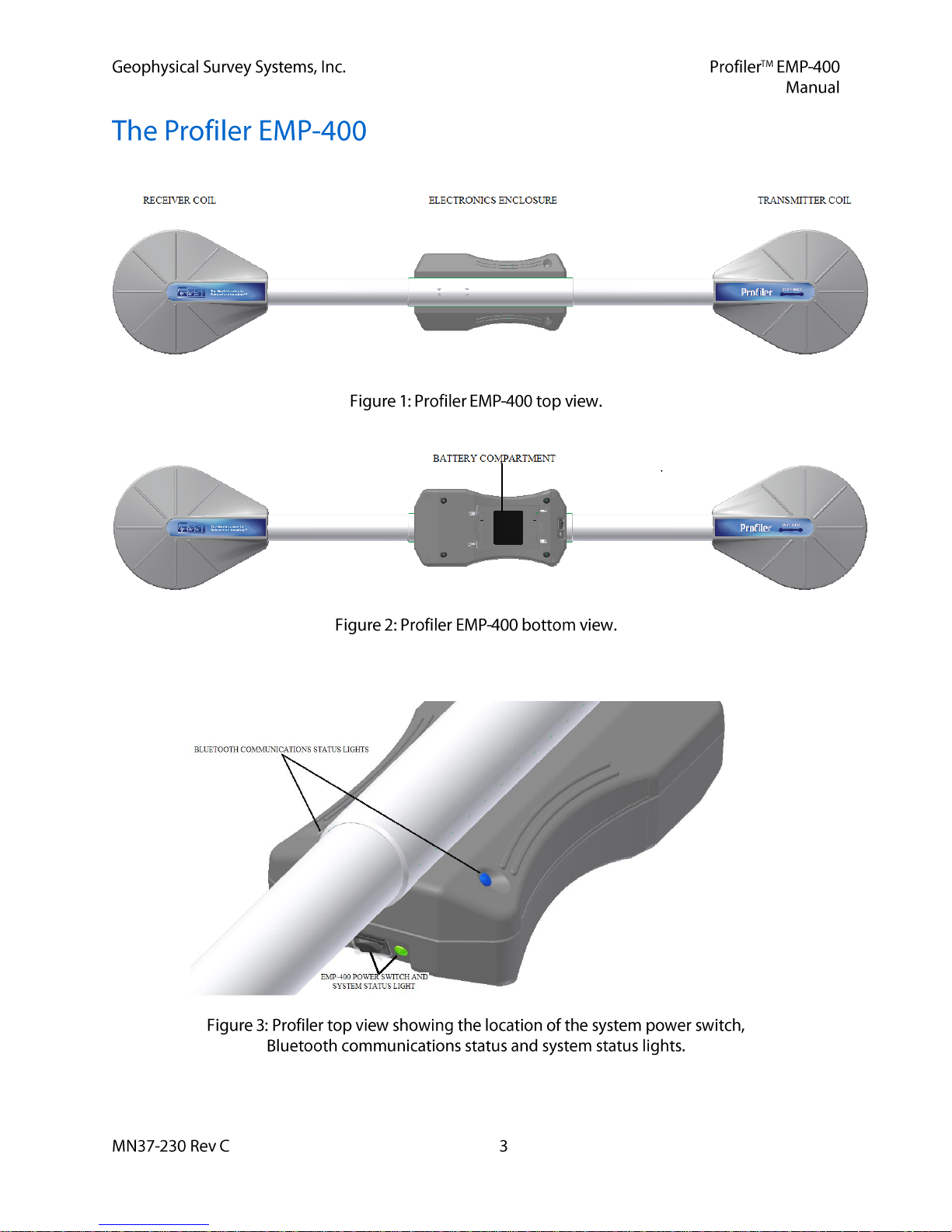
The Profiler has no external connectors or I/O ports. An expanded view of the Profiler electronics
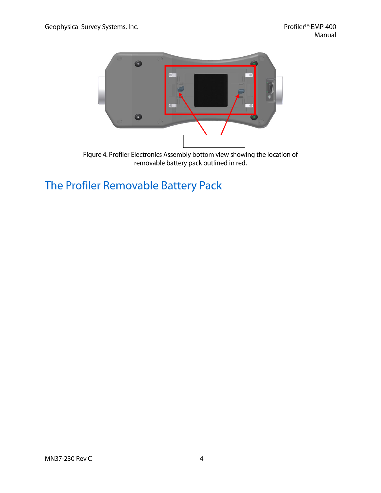
enclosure is illustrated in Figures 3 and 4.
The Profiler is powered by re-chargeable Li-Ion batteries. The batteries are accessible via the removable
battery pack located on the bottom of the electronics assembly.
Retaining Clip Locks
The battery pack is removed from the unit by gently pulling the removable battery pack retaining springs
towards each other i.e., towards the center of the battery pack, until they snap out from beneath the four
(4) retaining clips screwed into the bottom of the electronics. The locks on the battery pack retaining clips
prevent the clips from accidentally opening when the electronics enclosure base brushes against tall grass,
field stubble, or other near-surface objects. Engage the locks by turning the clip locks 90 degrees
clockwise. The operator can use the reverse end of the PDA stylus as a tool to turn the locking tabs.
The removable PDA battery pack accepts the 10.8 VDC Li Ion batteries provided with your system.
Operation time of the Li Ion battery on a single charge is ~ 9 - 12 hours of continuous use when
operating at one measurement per second at ambient temperature of 59 F to 95 (+15o C to +35o C).
Operation time of the Li Ion battery on a single charge is 18 hours when operating at one
measurement per second at ambient temperature of 77 F (25o C). Life expectancy is 300
charge/discharge cycles. The discharge temperature limits are -14F to 122 F (10 C to +50C).
The storage temperature limits are -4F to 140F (-20 C to +60 C).
Fully charged battery status is indicated by five (5) rectangular black squares located on the battery
charge gauge on the end of the battery opposite the five (5) battery contact slots.
The Profiler Li Ion batteries should be placed in the Li Ion charger when the battery charge gauge
reaches one square. The time required to recharge a battery is three and a quarter hours for a fully
discharged battery.
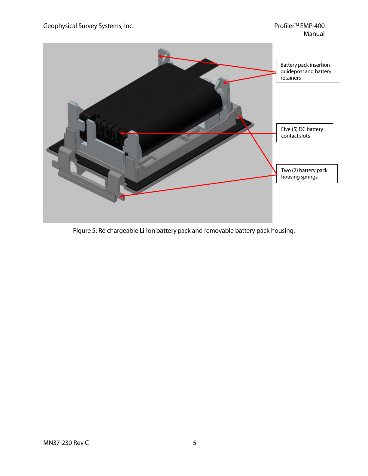
The Li Ion battery is inserted into the Profiler battery pack by inserting the battery and gently
pinching the battery pack housing springs back until the battery snaps into place.
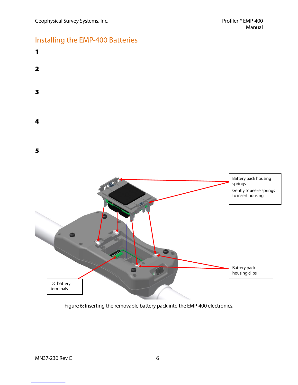
The battery pack is then inverted and then inserted into the electronics enclosure. The User should
gently squeeze the battery pack retaining clips and then insert the battery pack into the Profiler
electronics assembly using the insertion guideposts.
The battery must be installed into the removable battery pack correctly. The five (5) DC contact slots
on the Li Ion should align with the DC battery terminals located on the electronics assembly board
inside the removable battery pack enclosure. The battery should be inserted so that the five (5) battery
contact slots are facing UP.
Press gently on the top of the battery pack until the retaining springs click into place. Be certain the
clip locks have been rotated counter-clockwise (unlocked) before pressing on the retaining springs.
The pack can be removed by gently pinching the battery pack housing springs until the springs unsnap from beneath the four white battery pack housing clips.
The system can now be turned ON by pressing the power button located at the front of the electronics
assembly. The Green power LED should illuminate. This indicates that the system is receiving power
from the battery pack and that the voltage level of the batteries is sufficient to operate the system.
The Tripod Data Systems (TDS) Recon-400 is a portable, field rugged PDA. It is the platform for the
Graphic User Interface and data storage of the Profiler.
GSSI assumes no responsibility for Profiler interface operating difficulties if the User installs
any additional third-party software in the Profiler PDA or reconfigures the PDA Bluetooth connection
for operation with any other devices.
The Recon-400 incorporates an Intel PXA255 X Scale CPU running at 400 MHz.
It is configured with 64 MB high-speed SDRAM and 256 MB of non-volatile storage.
The system display is a 240 X 320 pixel (1/4 VGA) color TFT display with LED front light.
It is configured with integrated Bluetooth communications and a 22-channel WAAS GPS receiver.
Available Profiler PDA user storage memory is 248 MB. The system is capable of storing 500,000
readings in both continuous mode and discrete mode.
The PDA weighs 17 ounces (.481 kg) and has an operating temperature range of -22F to – 140F
(-30C to +60 C). Storage temperature limits are -40 to 158 F (-40 to +70 C). Battery life is
500 charge/discharge cycles (typical) if battery is stored at least partially charged at 32F – 95F
(0 to +35 C).
The system meets MIL-STD-810F standards for humidity, water (accidental immersion), drop,
vibration, humidity, and altitude. It has an IP67 rating and is impervious to water and dust.
A rechargeable 3800 mAH NiMH DC power boot module.
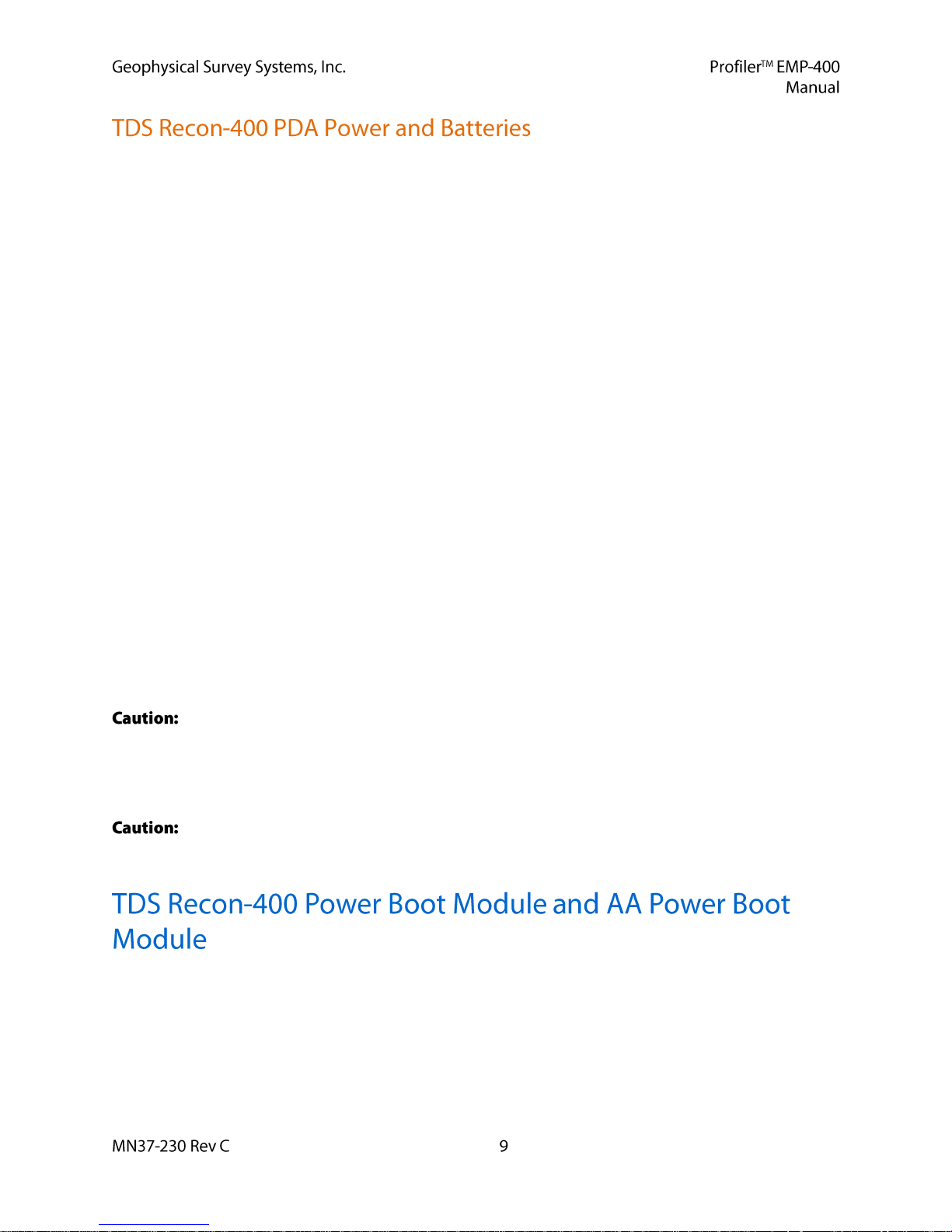
Input/Output and power ports include a D-shell RS-232 serial port, a USB data port, and AC charging
connector for the AC power boot module.
The Operating System software is Windows Mobile 6.0 (or higher).
The TDS Recon-400 has three (3) primary connectors: One (1) AC battery charger connector,
One (1) D-Shell RS-232 serial port connector and one (1) USB data port.
The Recon-400 Windows operating system has on board power management and a battery gas gauge.
The User should place the PDA on charger upon unpacking the instrument. The Windows operating
system is stored in non-volatile memory. GSSI recommends placing the PDA on the charger for several
hours after every survey or when the PDA battery gas gauge reads 25% or less.
PDA battery level information is accessible by selecting the Windows Start tray icon and selecting the
Settings option.
Select the START > Settings > System tab and select the Clocks & Alarms icon to access the clock
settings for the PDA. Set the appropriate time for your location and the appropriate date prior to
collecting data with the system.
The On Battery Power device shutdown parameters been turned OFF at the factory to prevent
inadvertent shutdown of the system and display and to prevent interruptions of Bluetooth
communications during a survey. The User should not modify these settings.
The On Battery Power device shut down and On External Power device shut down parameters for the
Screen Power and Backlight Brightness have been set at the factory to prevent inadvertent shutdown
of the system, and display and interruptions of Bluetooth communications during a survey. The User
should not modify these settings.
The Sounds and Notification parameters have been set at the factory. The User should not modify
these settings.
When using the AC rechargeable power boot module, under normal operating conditions, the Recon-
400 should operate for up to 4.5 - 5 hours. When using the WAAS GPS system, operating time drops
to ~2.5 - 3 hours.
Operating the PDA with less than 25% battery power may result in intermittent loss of Bluetooth
communication and potential loss of data. GSSI recommends that the PDA power boot module be
recharged when the power level reaches 25%.
Under no conditions should the user modify the PDA Screen parameters. The window
orientation is set at the factory to Portrait by default. Changing the window orientation could lead to
unpredictable operating display results when running the Profiler interface. GSSI assumes no
responsibility for Profiler interface operating problems if the display orientation is changed by the
user.
The PDA should not be placed on the charger for longer than a 12 hour period. Charging the
PDA Power Boot Module for longer than 12 hours repeatedly may damage the power boot module.
The Recon-400 is supplied with the rechargeable power boot module installed. The power module can be
removed from the PDA by turning the module locking tabs to the unlocked position. The Recon PDA is
supplied with a screen stylus that has a screwdriver tool opposite the stylus end. This tool is used to lock
and unlock the power boot modules and the protective cap for the WAAS GPS card. The modules can be
secured by returning the locking tabs to the locked position. The location of the locking tabs is illustrated
in Figure 10.

The AA power boot module accepts two (2) AA batteries. Under normal operating conditions and with
the appropriate batteries, the AA power boot module will operate for approximately 2-3 hours. When
using the WAAS GPS, the PDA operating time drops to .5 hours.
Your Profiler is supplied with a shoulder strap for hip height deployment and a low carry handle for nearsurface deployment. The system is supplied with two (2) Velcro cinch straps that are secured to the
Profiler body tube by adjusting the strap tension. The straps have attached plastic clips, allowing the User
to clip the Profiler carrying strap to the cinch straps. The Velcro cinch straps and the shoulder-carrying
strap are adjustable. The Profiler shoulder strap should be adjusted so that the instrument is approximately
1 meter from the ground surface.
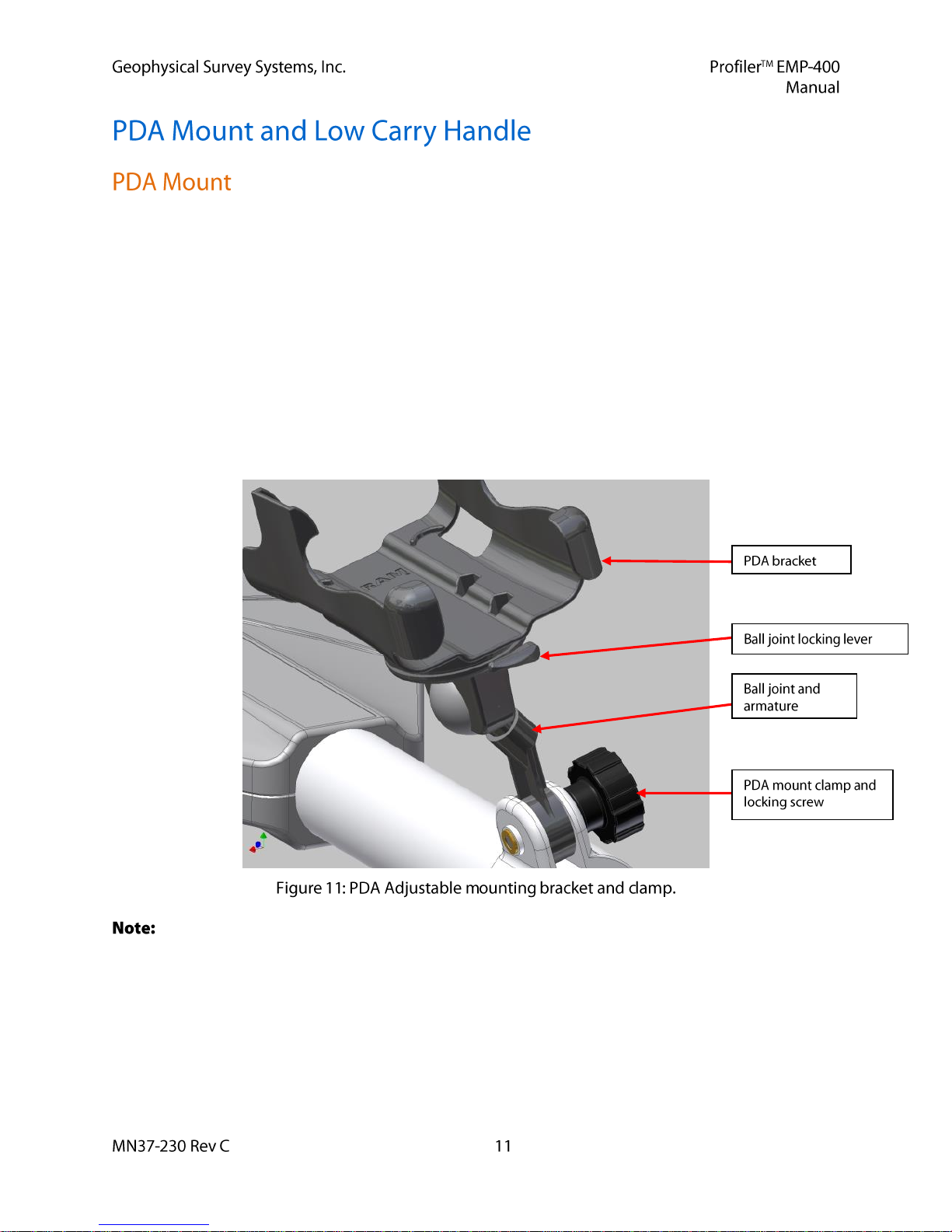
The PDA mount attaches to the main tube of the EMP-400 with a screw-clamp. The PDA is designed to
slip into the black plastic bracket on the PDA mount. If inserted properly, the PDA should click into
place. The orientation of the PDA can be adjusted for easy viewing by the operator. The PDA mount
incorporates a lockable ball joint and armature adjustment that allows the user to adjust the pitch and the
angle of the PDA screen. When the desired pitch and angle adjustment has been made, use the ball joint
locking lever to lock the PDA into position by moving the lever from the horizontal to vertical position.
Do not force the ball joint armature without unlocking the ball joint. This will damage the ball joint.
GSSI does not recommend using PDA mount when the low carry handle is used. The PDA display
will not be visible to the User.
Figure 12 illustrates the PDA mount with the PDA inserted and the shoulder carry strap attached to the
Profiler body tube. The PDA mount clamp should be attached to the instrument so that the clamp butts up
against the tube section to which the electronics enclosure is attached. This position provides better
balance to the instrument when using the shoulder strap.
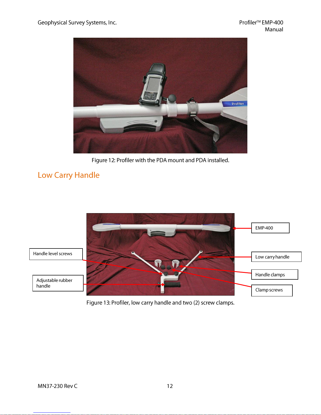
The Profiler handle allows the User to carry the instrument in closer proximity to the ground surface. The
Profiler In-Phase response will improve the closer it is to the ground surface. The low carry handle is
attached to the tube with the two screw-clamps provided with the handle. The low carry handle, clamps
and clamp screws are illustrated Figure 13.
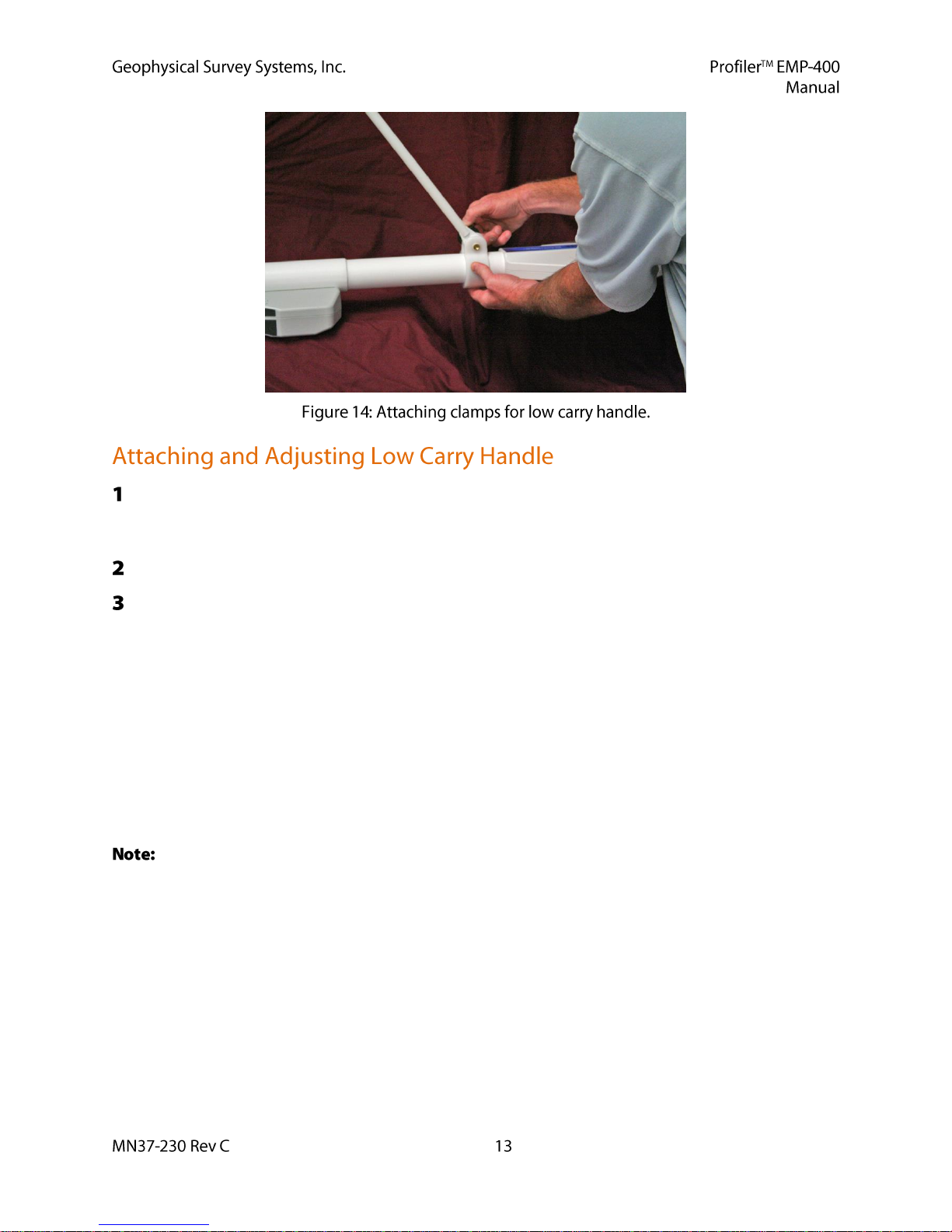
Position the clamp and the handle as shown in Figure 14 and insert the clamp screw through the blind
side of the handle clamp, i.e., the side of the clamp opposite the threaded brass insert, and through the
rubber bushings at the bottom of the carry handle.
Slowly screw the threaded clamp screw through the clamp and handle until the screw is tight.
Repeat this process with the other handle clamp.
The height of the handle can be adjusted by loosening the handle clamps and sliding them
towards (lower) or away (higher) from the EMP-400 coils.
The User can also adjust the handle height by removing the rubber handle screw and
repositioning the rubber handle in one of the three (3) pre-drilled holes in the carry handle.
The level of the instrument can be adjusted by loosening the two handle level screws beneath the
handle and adjusting the handle until the handle and EMP-400 are level. The handle level can be
checked by placing the Profiler on a flat surface and the handle screws adjusted as necessary.
The recommended deployment height when using the low carry handle is 8 – 10 inches
(20 to 25 cm) from the ground surface.
To obtain reasonable apparent conductivity (a) values GSSI recommends that the Profiler be
deployed with the low carry handle and operated at a transmit frequency of 15 kHz. This is discussed in
detail in Chapter 2.
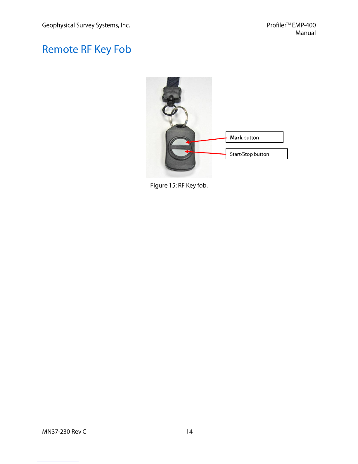
The EMP-400 is supplied with a remote RF key fob for remote Start/Stop of Profiler during data
acquisition and for placing fiducial marks in data files collected in the Continuous mode.
GSSI strongly urges the User to review the system setup procedures in Chapter 2 carefully and use them
as a step-by-step guide when configuring the system.
Prior to starting system setup and data acquisition, insert a fully charged Profiler Li-ION battery into the
removable battery pack (see Section 1.4: Profiler Removable Battery Pack).
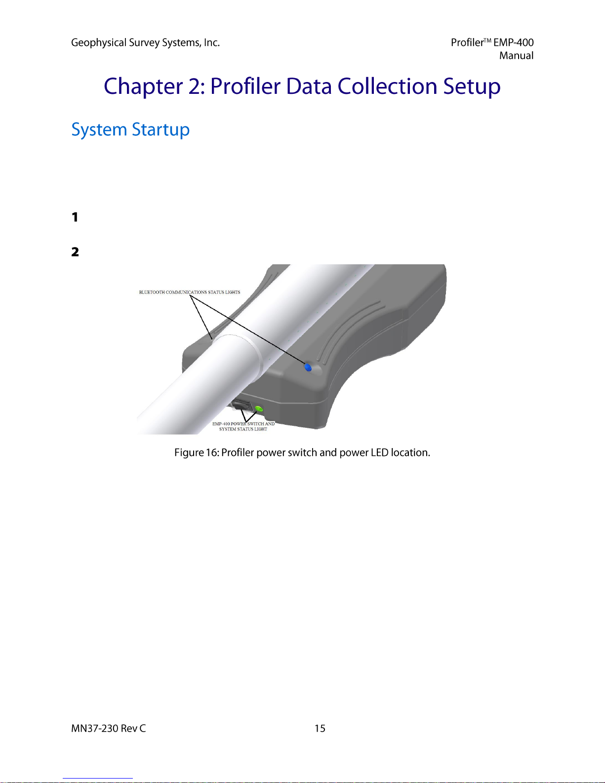
Turn ON the Profiler. The Green power status light next to the Profiler power switch will illuminate.
The Blue Bluetooth communication status lights will also illuminate.
Turn ON the PDA by pressing the PDA Power ON/OFF button.
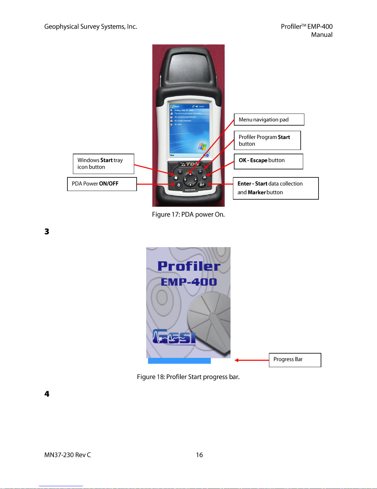
After starting the Profiler software program, the RECON-400 will display the PROFILER splash
screen.
Beneath the splash screen a Blue progress bar will appear. When initialization is complete, the
progress bar and splash screen will disappear and the Main menu will be displayed.
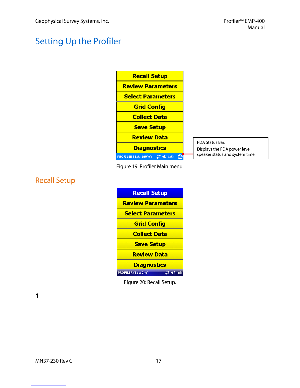
When communication is established between the Profiler and the PDA, the PDA will display the Main
menu. At the bottom of the screen, the PDA battery charge status, the speaker status (On/Off) and the
current system time are displayed.
If the User has stored a previously saved setup it can be recalled by selecting Recall Setup and then
selecting the desired setup number. Thirty (30) User-defined setups can be stored in the PDA
memory. Once system setup is complete, the User can store the setup for future use by selecting Save
Setup from the Main menu and select a setup number.
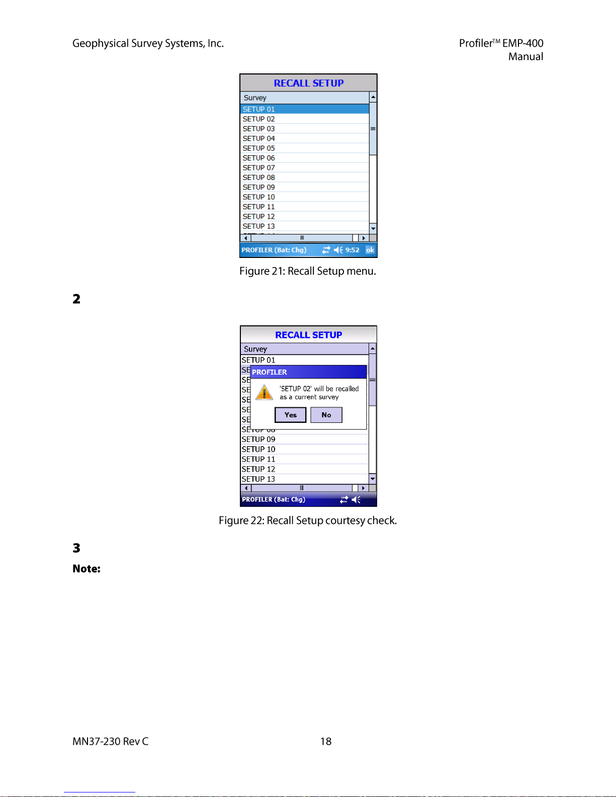
To recall a setup the User should select Recall Setup from the Main menu and select the desired setup
number.
The system will prompt the User with a courtesy check above. The User should select YES.
The GPS setup and the system calibration parameters are NOT saved in a Saved setup. If the User
is using a GPS, a GPS test must be conducted with the Internal or External GPS to assess the GPS signal
condition and GPS validity. If the operator is using an external GPS system, it should be connected to the
PDA serial communications port at this time. The User must also perform a system calibration prior to
data collection.
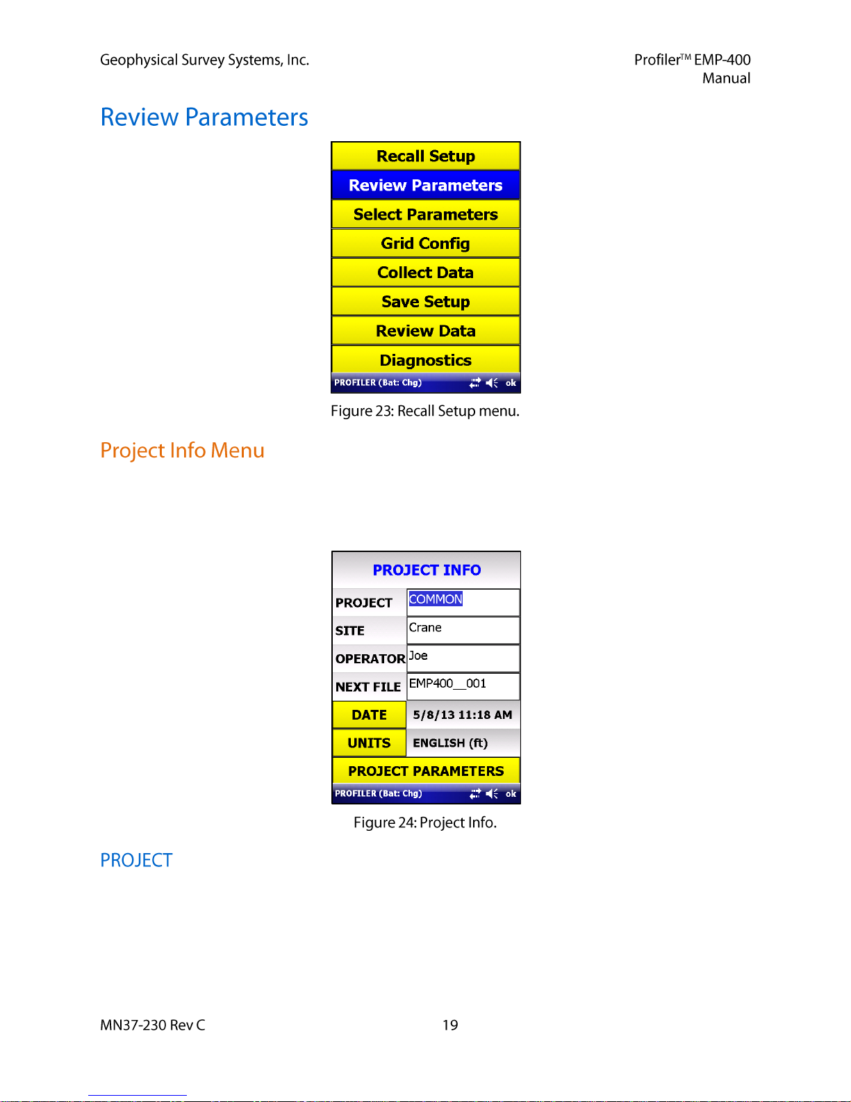
Prior to starting the survey, the User may record project information for permanent record. Site data often
includes a Project name which may consist of a site location or job number. In addition, the identity of the
operator, the date and time when the data was collected and the units (English or Metric) are all useful
information to archive. This information may be entered into the PDA by selecting Review Parameters.
This field can contain alphanumeric information about the survey being conducted. This information will
be used to create a Project folder in the \Profiler\DATA directory on the PDA into which all the data files
will be written. This field can contain a maximum of 21 characters. The default Project folder is
COMMON.prj.
The User can enter information on the job site or location. This field can contain a maximum of
21 characters.
The User can enter information on the system operator. This field can contain a maximum of
21 characters.
This field contains the File Name and Number of the next data file to be collected. The default data file
names are written in the form EMP400___001.EMI.
The file name format can be changed by the operator. EMI files are stored as BINARY files in the PDA.
They are converted to ASCII text files upon data transfer from the PDA.
The number field of the default file names will continue to increment until manually reset or
changed by the User. The file number field does not automatically reset when the PDA is turned off, or
data is transferred from the PDA by the user.
This field displays the date and time. This field is not updated automatically. Prior to beginning data
collection, the User must select the Date field. This will update the date and time the current system time
set on the PDA.
This field displays the linear units that will be used in the Grid Config. menu for the grid limit values as
well as the reading\station increment and the transect spacing. This field will toggle between English and
Metric units. When the desired system of units has been entered, tap OK to return to the Review
Parameters menu.
The User should select a system of units at the beginning of a survey. The User should not change
units during the course of the survey, as the conversion from one set of unit to the other will result in
floating point errors in the distance conversion.
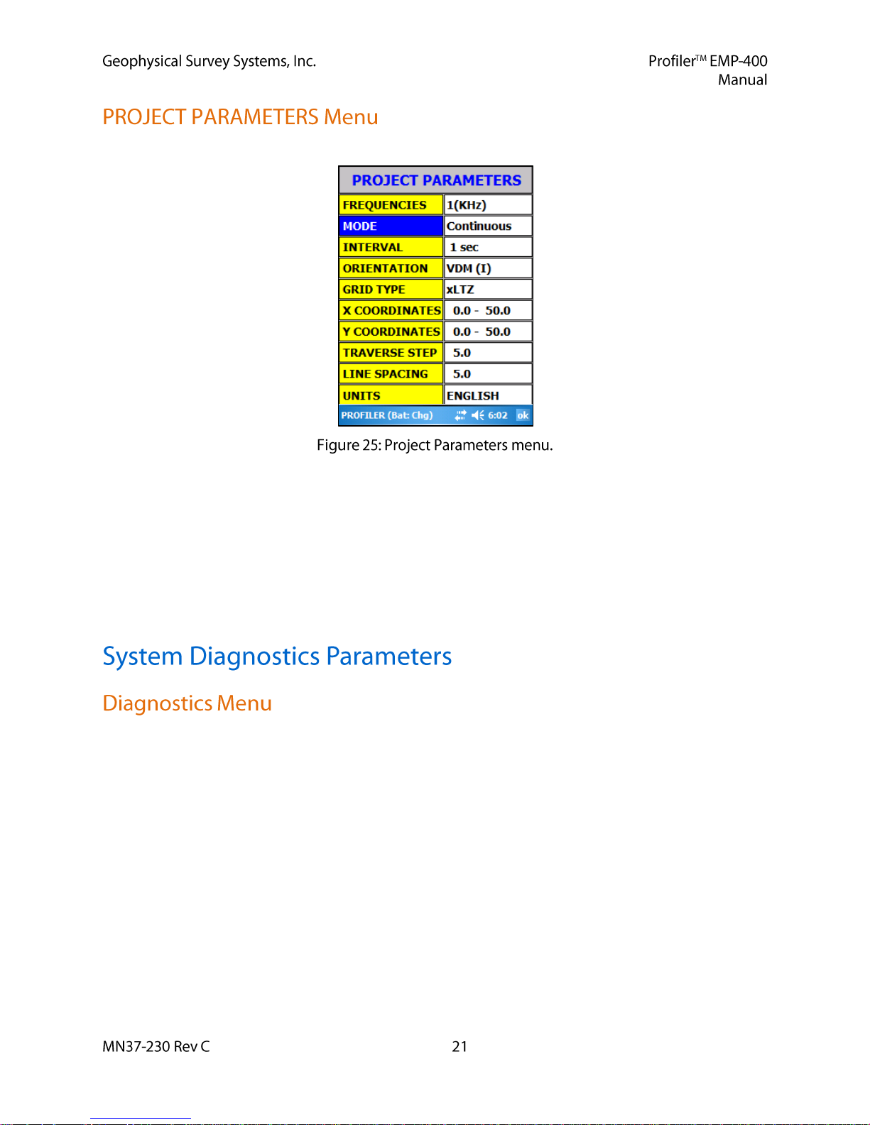
To access the Project Parameters, the User should select Project Parameters.
The Project Parameters screen displays all of the User selectable data acquisition parameters and Grid
Configuration parameters.
The Project Parameters menu can be accessed directly from this menu by selecting any of the Parameter
fields; Frequency, Mode, Interval, or Orientation. This allows the user to quickly change any acquisition
parameters if survey requirements change.
The Grid Configuration menu can be accessed directly from this menu by selecting the Grid Type, X
Coordinates, Y Coordinates, Traverse Step or Line Spacing.
The User should check the parameters in the Diagnostics menu to ensure that the system is properly
configured by selecting Main > Diagnostics.
GUI (page 22)
Firmware (page 22)
Upgrade Firmware (page 22)
System Calibrations (page 22)
Display Preferences (page 23)
System Setup (page 28)
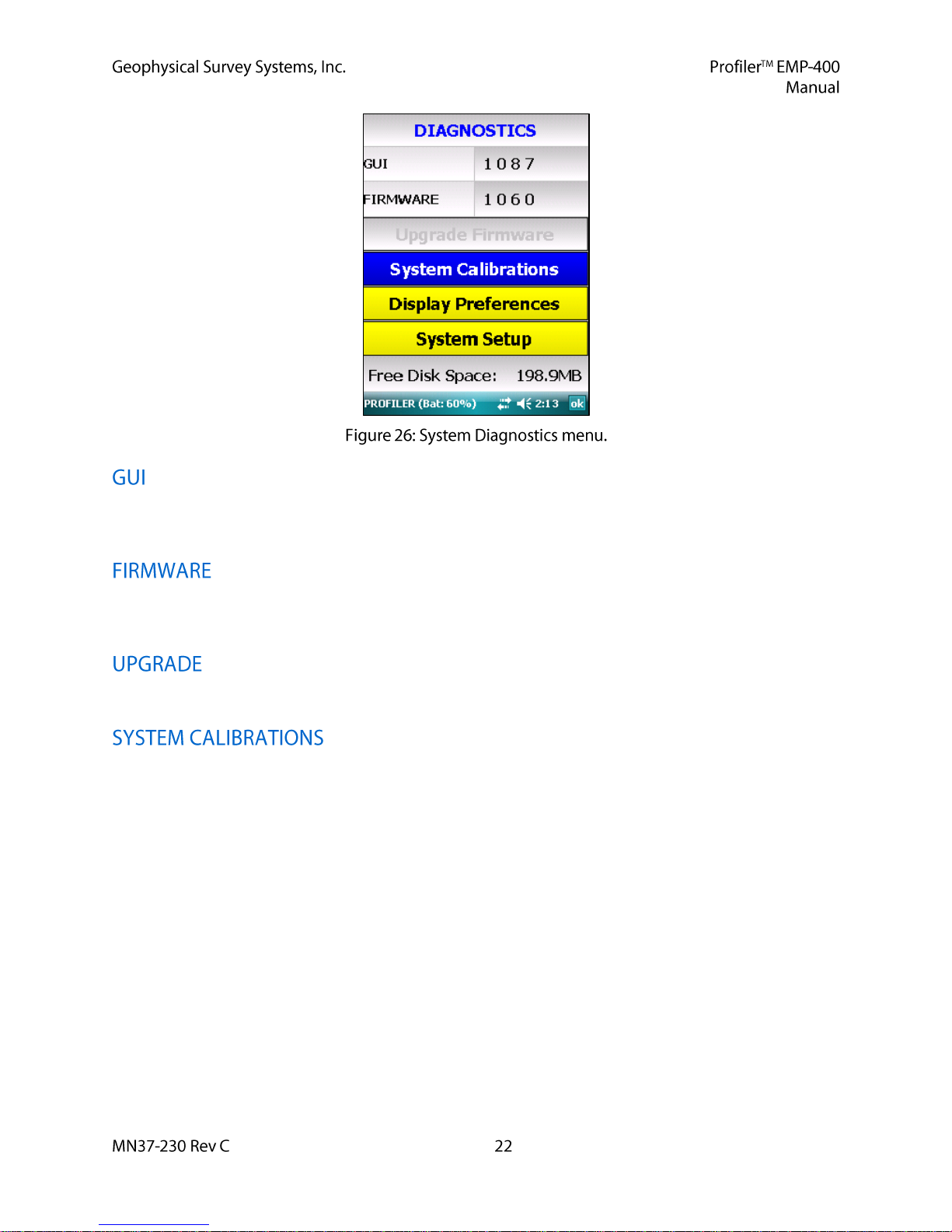
The field displays the Graphic User Interface (GUI) version installed on the PDA. This field is for
information purposes only and cannot be changed or accessed by the User.
This field contains information on the Firmware version number installed on your Profiler. This field is
for information purposes only and cannot be changed or accessed by the User.
This function can only be accessed with a GSSI supplied installation update file.
Slection of this field opens the Systems Calibrations menu where the User must perform several required
calibration functions prior to data collection.
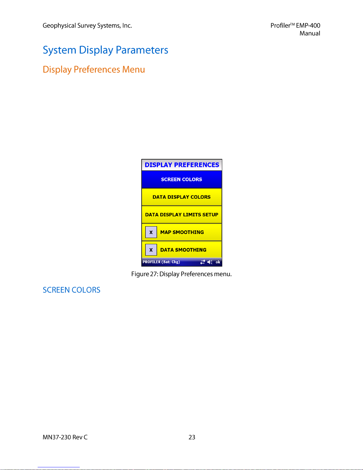
The User should select Display Preferences to set the display paramters for the PDA.
Screen Colors (page 23)
Data Display Colors (page 24)
Data Display Limits Setup (page 25)
Positioning Dsiplay (page 25)
Map Smoothing (page 27)
Data Smoothing (page 27)
The Screen Colors menu allows the User to customize all of the system setup menus, tool bar labels and
background colors. Customization of the system displays is entirely up to the User. In some cases, it may
be desirable to change the colors of certain fields to enhance the menu display in high (or low) ambient
light conditions. Both the Text and Background color of the Edit Box, Header, Label and function Button
may all be customized.
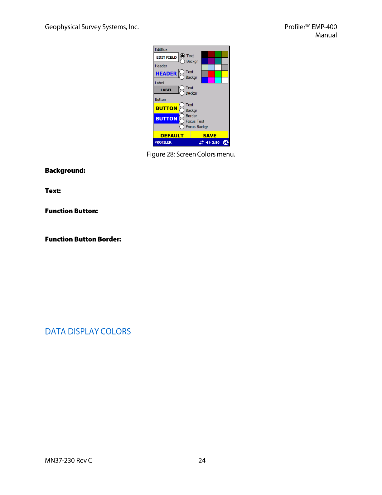
To change the Background, the User must select Backgr next to the specific field to
customize and then select the desired color from the color palette on the left of the display.
To change the color of the Text, the User must select the Text next to the specific field to
customize and then select the desired color from the color palette on the left of the display.
Customization of the Function button includes the Text, Background, Border, Focus
Text and Focus Background. Customization of the Text and Background for the Function buttons are the
same as that for the Edit Box, Header and Label.
The function Button Border (the border around the Function button) Focus
Text (active menu selections under the function Button) and Focus Backgr (the background behind the
Focus Text) allow the user to further customize the function Buttons as desired.
GSSI recommends that the User experiment with these functions. Once the desired colors have
been chosen, select Save.
At any time the User may return the system to the default color settings by selecting SET
DEFAULTS.
When the User is satisfied with any changes, select Save, then OK from the PDA Status Bar to return to
the Display Preferences menu. Select OK from the PDA Status Bar to return to the Diagnostics menu.
The Data Display Colors menu allows the User to select a specific color for the In-Phase, Quadrature, and
Conductivity line graph, bar graph and alphanumeric data dislays.
 Loading...