

Page 1
STP 500
Default access data (HTML + SFTP):
192.168.0.120
User: admin
Password: geheim
Assembly Instruction
Page 2

Contents
1 Safety regulations and notes ........................................................................4
2 General information ....................................................................................6
2.1 Packing contents ............................................................................6
2.2 Meaning of the symbols used ..........................................................6
2.3 Technical data ...............................................................................6
2.4 Description ...................................................................................8
General ........................................................................................8
3 Assembly ....................................................................................................9
3.1 Device overview ............................................................................9
3.2 Installing the device .....................................................................10
3.3 Connecting the device ..................................................................11
Power Supply ..............................................................................11
Streaming Interface ......................................................................11
Configuration/WAN Interface .......................................................11
4 Configuration ............................................................................................ 12
4.1 Initial configuration ......................................................................12
4.2 Configuration ..............................................................................15
Overview window .......................................................................15
Perform changes .........................................................................16
Streaming ...................................................................................17
Tasks Overview ......................................................................17
Add New Task / Edit Task .......................................................18
- Task Type Media ...................................................................18
- Task Type IPTV, IP Radio/Web Radio .......................................20
- Task Type CCTV ....................................................................23
Converter for Media ....................................................................25
System menus .............................................................................26
User Management ..................................................................26
Network ................................................................................28
OpenVPN .............................................................................30
Firmware ...............................................................................31
- Backup: ...............................................................................31
- Factory reset: .......................................................................31
- Firmware update: .................................................................32
Reboot the system ...................................................................33
Shut down the system ..............................................................33
USB Functions ........................................................................33
- 2 - STP 500
Page 3

- Copying media data to the device: .........................................33
- Reset network settings: ...........................................................34
- Reset administrator password: ................................................34
- Firmware update via USB: .....................................................34
Appendix ......................................................................................................35
Transfer media data to the device ..................................................35
Media2TS – Converter Software ....................................................36
- 3 - STP 500
Page 4

1 safety regulations and notes
• Observe the instructions for use of the hardware distributor enclosed with
the device - especially the safety instructions contained therein.
• This device is subject to the provisions of protection class I. Operate the
device only to mains sockets with protective conductor connection!
• If the power cords need to be replaced, only use OEM power cords.
• Before starting installation or service work disconnect the receiving system
from mains.
• Assembly, installation and servicing must be carried out by an authorised
electrician.
• Caution! Dangerous voltage! For a complete disconnection from the mains,
the mains plug must be pulled out of the mains socket. Ensure that the mains
plug can be pulled out without difficulties.
• Install the device
- in a dry, dust-free environment, in such a manner that it is protected from
moisture, fumes, splashing water and dampness
- where it is protected from direct exposure to sunlight
- on a vibration-free wall or floor construction
- not within the immediate vicinity of heat sources
• In case of the formation of condensation wait until the system is completely
dried.
• Ensure that the device is adequately ventilated.
• Do not cover the ventilation openings!
• Do not install the device in cabinets or recesses which are not ventilated.
• Do not place any vessels containing liquids on the device.
• Do not place anything on the device which could initiate fires (e.g. candles).
• Avoid short circuits!
• No liability is accepted for damage caused by faulty connections or inappropriate handling of the device.
• The firmware contains components which are licensed as Open Source
software. This parts of software source code can be provided at cost price
on CD upon request. The licensee is granted a non-exclusive right of use for
the Open Source Software by the respective right holders used; the conditions stipulated by the respective valid license terms apply. The license terms
of this license only apply to the components which are not listed as Open
Source software.
In relation to the licensor the regulations on liability and warranty in these
license terms apply for the whole software. The liability and warranty regu-
- 4 - STP 500
Page 5

lations of the Open Source licenses only apply in relation to the respective
right holders.
• The device is intended for the playback/streaming of picture and sound
signals ("Materials"). The use must be taken place in conformance with applicable laws, license agreements or service agreements under which you
have obtained access to such Materials. Any other use is expressly prohibited. It is Your responsibility to comply with, and you agree to be bound by,
all such applicable laws and agreements. Unauthorized copying, streaming
of copyrighted material, or providing copies of such material to others, may
infringe the rights of copyright owners and may also be a criminal offence
in some jurisdictions.
Prior permission from the copyright owners may be required for certain
public performances and certain commercial uses. You agree to indemnify
and hold harmless GSS Grundig Systems GmbH and its Licensors against
any breach by You of applicable copyright restrictions in connection with
your use of the device.
• Test the firmware versions of the device and update them if necessary. The
current firmware version can be found at "www.mygss.eu".
Take action to prevent static discharge when working on the device!
Electronic devices should never be disposed of in the household rubbish. In accordance
with directive 2002/96/EC of the European Parliament and the European Council from
January 27, 2003 which addresses old electronic and electrical devices, such devices
must be disposed of at a designated collection facility. At the end of its service life,
please take your device to one of these public collection facilities for proper disposal.
- 5 - STP 500
Page 6

2 general information
2.1 PaCk in g Co nt ents
1 STP 500
1 Mains cables
1 Brief assembly instructions
2.2 meani ng of t h e sym b o l s us e d
Important note
Danger by electrical shock
—> General note
• Performing works
2.3 te C h n iCal da ta
The product fulfils the guidelines and standards for CE labelling.
Unless otherwise noted all values are specified as "typical".
Stream output
Simultaneously possible streams (default) .................................................5
Protocols ...................................................................................RTP/UDP
File format .....................................................................Transport Stream
Transcoder
Video Codecs .................................................................MPEG-2; H.264
Video Bitrates (kb/s) ......................800; 1000, 1200, 1400, 1800, 2400,
3200, 4000, 6000, 8000
Video Formats .................................................720x576@25/30/50/60;
1280x720@25/30/50/60;
1920x1080@25/30/50/60
Audio Codecs ................................................................MP2; MP3; AAC
Audio Bitrates (kb/s) .................................................128; 192, 256; 320
Hardware
Power supply ...................220-240V 50/60Hz; 200 W (80+ Gold > 87%)
Dimensions (19 "/ 1U) .....................43 mm (H), 437 mm (W), 249 mm (D)
- 6 - STP 500
Page 7

Recommended ambient temperature (according to BSI) .............. 20 - 22 °C
Recommended humidity ........................................................... max. 40 %
Recommended location .................To ensure optimum cooling of the system,
we recommend, to operate the device in an
air-conditioned room in a dedicated rack.
Interfaces
LAN 1000-BASE-T: ............................................................. 2 RJ45 socket
Data rate: ......................................................................... ≤ 800 MBit/s
Protocols: .......................................................... UDP (User Data Protocol),
RTP (Real-Time Transport Protocol)
USB sockets ......................................................................2 x USB A 2.0
USB sockets ......................................................................2 x USB A 3.0
- 7 - STP 500
Page 8

2.4 des Cr i P tion
The media streamer can play back video/audio files stored on the internal
hard disk. These video and audio files must be in *. ts format during playback
so that TV sets and set-top boxes can display them.
The transcoder is used for the adaptation (transcoding) of non-DVB-compliant
data streams in "real time".
All common formats (mkv, avi, divx, mp4, mov, mpeg) can be transcoded into
the transport stream format (*.ts) for the media streamer.
ge n er al
The configuration of the device is to be done via an HTML user interface via a
PC and a standard HTML browser connected to the configuration interface.
The streams for the media streamer are transferred to the hard disk via a SFTP
access or USB interface.
They are output at the streaming interface.
—> You will find descriptions to important terms for configuring a
streaming network in menu Help > Multicast Setup.
If the configuration interface is con-
nected to the Internet, after the initial
setup, you can get worldwide access to the station via an OpenVPN
connection – by PC, tablet or smart
phone with Internet access.
GSS
OpenVPN
Server
—> When using mobile terminals – dependent on your mobile contract
– additional connection costs / data transfer costs may also be
incurred here.
- 8 - STP 500
Page 9
3 assembly
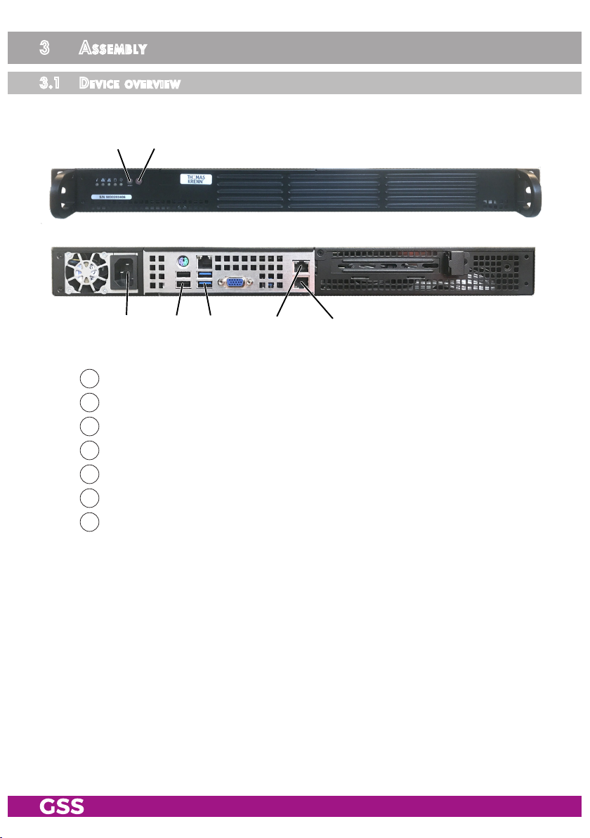
3.1 deviC e ov erview
2
1
3 4 5 6 7
1
Power switch (on/off)
2
Reset
3
IEC connector C14; connector for mains cable
4
USB-A 2.0 interface
5
USB-A 3.0 interface
6
Configuration/WAN interface
7
Streaming interface
- 9 - STP 500
Page 10
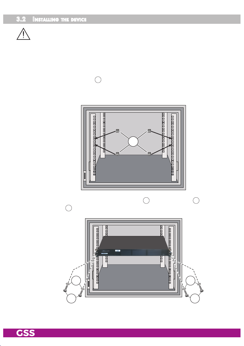
3.2 inst alli ng the d e v i C e
– The device is meant exclusively for use in rooms with normal operating
conditions (temperature, humidity, radiation) such as air-conditioned server
rooms, offices and publicly accessible rooms with similar conditions. To ensure optimum cooling of the system, we recommend, to operate the device
in an air-conditioned room in a dedicated rack (recommended ambient temperature according to BSI 20 - 22 °C; recommended humidity max. 40 %).
• Attach four cage nuts 22 at the installation site.
We recommend the use of lateral slide rails/component carriers in order to
relieve the front panel.
22
• Screw the unit with the mounting screws 24 and the washer 23 to the four
cage nuts 22.
2323
2424
- 10 - STP 500
Page 11

3.3 Con ne C ting the d e v i C e
Pow er su PP ly
• Connect the attached mains cable to the IEC connectors C14 3.
• Connect the mains cable to mains socket with protective conductor connection. Thereby note the voltage specified on the device.
—> This device has no primary power switch and is in standby mode im-
mediately after connecting the operating voltage. Power ON/OFF
1
switches only the secondary DC voltages!
For a complete disconnection from the mains, the mains plug must
be pulled out of the mains socket. Ensure that the mains plug can be
pulled out without difficulties.
str e a m i n g int e r fa C e
• Configure the device (page 12).
• Make sure the LAN network is adapted and configured for streaming!
Therefore note menu Help > Multicast Setup.
• If the programming is finished connect the streaming interface 7 to the
LAN network via a CAT 6 cable.
Confi gu r at io n/ wa n inter faC e
• After the initial configuration, connect the configuration/WAN interface 6
to the LAN network using a CAT-6 cable if you want to process content from
the Internet or have remote access.
- 11 - STP 500
Page 12
4 Configuration
The configuration of the device is to be done via an HTML user interface via a
PC and a standard HTML browser.
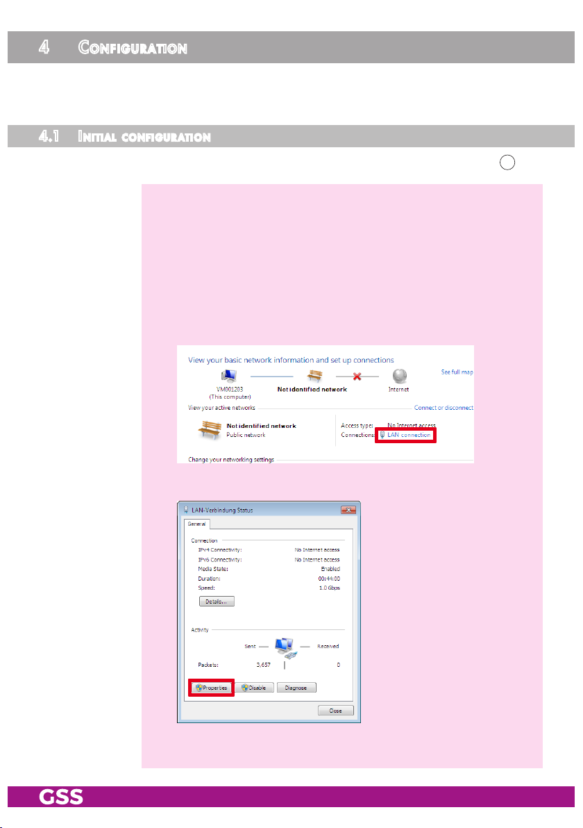
4.1 init ia l C o n f i g ur at i o n
• Connect a PC via a LAN cable directly to a configuration interface 6.
—> The PC and the device must be within the same network (same IP
address range). Cookies must be accepted and JavaScript must be
active.
Use current browser versions.
—> Example for IP address setting with Windows 7 operating system:
• For the initial setup open the properties for TCP/IPv4 of the PC:
> Control Panel
> Network and Sharing Center
> LAN connection
> Properties
- 12 - STP 500
Page 13

> Internet Protocol Version 4 (TCP/IPv4)
> Properties
• Activate point "Use the following IP address".
• Enter e.g. 192.168.0.2 for the IP address.
• Enter for the Subnet mask 255.255.255.0.
• Confirm the setting with "OK".
- 13 - STP 500
Page 14

• Start the browser, enter the IP address of the device (factory default is
192.168.0.120) and start the establishment of the connection.
• Enter user admin and your Password and click on button "Login".
The default password is geheim.
—> For further logins observe the menus System > Network, System >
User Management and System > OpenVPN!
—> The Overview window is displayed.
—> Changes in the menus are only transmitted to the device when you
click the button!
- 14 - STP 500
Page 15

4.2 Co n f i g ur at i o n
o v e r v iew w i n d ow
50
51
52
55 56
57
58
70
53
59
54
69
50
You can also reboot (page 33) or shut down (page 33) the system.
In all menus you will return to the Overview via the button Overview.
51
The Streaming button takes you to the settings for streaming (page 17).
52
The Converter for Media button takes you to the settings for converter
(page 25).
53
Via the selection System you have access to the menus of the Sys-
tem settings User Management (page 26), Network (page 28), OpenVPN
(page 30) and Firmware (page 31).
54
- 15 - STP 500
Overview of the streams set, with type, source, multicast address and serv-
ice name.
55
Herein the installed firmware version is displayed.
56
Via the Help menu you can call up the assembly instructions (PDF) as well
as hints about the configuration of a multicast network (PDF).
57
Herein the date and time of the last login is displayed.
58
Select menu language (English/German)
Page 16

59
Here you can find network information about the LAN interfaces.
69
Here you will find system information:
Uptime: System Runtime
CPU load: processor load
HDD: Hard disk space occupied / maximum
RAM: Working memory used / total
CPU temp: System temperature
USB-Stick: USB operations
70
Via button Logout you can leave the graphical user interface.
Perfo r m C hange s
Before leaving a menu, changes must be transmitted to the device.
• Therefore click on button .
After that is displayed for a short time in the upper right corner.
- 16 - STP 500
Page 17

str e a m i n g
ta s ks o v e r view
100
101
103
102
120
100
Use the button to add new streams (tasks).
You can enter any provider name here.
101
The Status column contains information about the streams ( stream on/
108
/
stream off/ stream not found).
102
In the
Alternative Stream on
Edit
column you can use the buttons to edit the respective stream.
Use the button to remove the respective stream from the streaming
list – not from the device.
—> Information about the media storage (system+media) is displayed in
the footer (HDD: used/maximum).
114113112111110106104
—> If the maximum possible number of streams (factory setting 5
streams) is reached, this is displayed:
—> If you need a larger number of streams (for a fee), please contact
our sales department. For this we need temporary access via a
working OpenVPN connection.
Depending on the task type
103
(media; IPTV, IP-Radio/Web-Radio;
CCTV) a corresponding editing window is displayed ( ) or offered for
selection for a new stream ( ):
103
—> Notes on the columns
tions of the editing windows of the various task types.
- 17 - STP 500
114
…
can be found below in the explana-
Page 18

ad d n e w ta s k / ed i t task
103
- ta sk tyPe me d ia
You can use the Media configuration window to output a transport stream file
Select the desired task type:
(*.ts) or multiple transport stream files one after the other in a continuous loop
as a multicast SPTS stream.
104
103
106
110
111
119
112
113
114
120
104
Switch the stream on or off here.
106
Select the transport stream file(s) you want to stream and confirm your
selection with the button . The selected files are displayed above the
selection field and can be removed from the list using the corresponding
buttons .
—> Media data is transferred to the hard disk via SFTP access (page 35)
or the USB interface (page 33).
—> If a file is no longer available, it is marked in the task overview (
file not found).
—> The Converter for Media menu allows you to convert other file for-
mats to the transport stream format (page 25).
- 18 - STP 500
Page 19

110
Indication of the Multicast IP Addresses
Multicast IP addresses are assigned to the streams. IGMP-capable switch-
es recognize the addresses automatically and, if configured accordingly,
route the streams only on request to end devices. This greatly reduces
network traffic.
—> IP addresses in the range 224.0.0.0-239.255.255.255 are mul-
ticast addresses, but many addresses in this range are reserved
(www.iana.org/assignments/multicast-addresses).
—> Use the 239.x.y.z range! It is suitable for streaming TV content and
must also be used for Panasonic Viera TVs.
For x use only the range of 1…127.
The range 0 ... 255 is available for y and z.
—> You will find descriptions to important terms for configuring a
streaming network in menu Help > Multicast Setup.
111
Setting the Multicast IP Port
112
Select the protocol UDP or RTP for this stream.
113
Enter the desired service name here.
114
Enter the desired SID, TS-ID and ON-ID as hexadecimal value.
119
With this button you apply all changes to the task overview.
—> Please note the following
120
Before leaving a menu, changes must be transmitted to the device.
120
.
• Therefore click on button .
—>
After that is displayed for a short time in the upper right corner.
- 19 - STP 500
Page 20

- ta sk tyPe iPtv, i P ra d io/we b ra d io
Using the IPTV, IP-Radio/Web-Radio configuration window, you can transcode
an IPTV stream or MP3 radio stream or an M3U playlist into the transport
stream format in "real time" and output it as a multicast SPTS stream.
104
103
105
106
107
108
110
111
112
113
119
114
120
104
- 20 - STP 500
Switch the stream on or off here.
Page 21

105
Select the type of data you want to receive:
IPTV - e.g. a TV or radio station which you provide with one of our head-
end stations as a SPTS stream.
Radio - e.g. an Internet radio station or an M3U file.
106
Enter the address (URL) of the source you want to stream.
—> Content from the Internet is "received" via the configuration inter-
face 6.
107
Select here whether the input signal is to be transcoded.
passthrough - converts the signal unchanged into a SPTS stream.
transcode - converts the signal into a SPTS stream according to the pa-
rameters you have selected.
—> Here you can, for example, transcode the AAC sound of an IPTV TV
or radio station into MPEG-1 Audio Layer II (MP2).
For radio stations/audio streams, you can store an image (*.jpg/*.png),
which is then displayed on the terminals.
—> Media data (e.g. an image) is transferred to the hard disk via SFTP
access (page 35) or the USB interface (page 33).
108
Here you can store an image (*.jpg/*.png), which is transmitted if the
signal of the source
106
fails.
Here you can also set the desired parameters for the image.
110
Setting of the Multicast IP Address
Multicast IP addresses are assigned to the streams. IGMP-capable switch-
es recognize the addresses automatically and, if configured accordingly,
route the streams only on request to end devices. This greatly reduces
network traffic.
—> IP addresses in the range 224.0.0.0-239.255.255.255 are mul-
ticast addresses, but many addresses in this range are reserved
(www.iana.org/assignments/multicast-addresses).
—> Use the 239.x.y.z range! It is suitable for streaming TV content and
must also be used for Panasonic Viera TVs.
For x use only the range of 1…127.
The range 0 ... 255 is available for y and z.
- 21 - STP 500
Page 22

—> You will find descriptions to important terms for configuring a
streaming network in menu Help > Multicast Setup.
111
Setting the Multicast IP Port
112
Select the protocol UDP or RTP for this stream.
113
Enter the desired service name here.
114
Enter the desired SID, TS-ID and ON-ID as hexadecimal value.
119
With this button you apply all changes to the task overview.
-> Please note the following
120
Before leaving a menu, changes must be transmitted to the device.
• Therefore click on button .
—>
After that is displayed for a short time in the upper right corner.
120
.
- 22 - STP 500
Page 23

- ta sk tyPe CCtv
The CCTV configuration window allows you to output the stream of a camera
as a multicast SPTS stream.
104
103
106
107
110
111
119
120
104
Switch the stream on or off here.
106
Enter the address (URL) of the source you want to stream.
112
113
114
107
passthrough - converts the signal unchanged into a SPTS stream.
transcode - converts the signal into a SPTS stream according to the pa-
- 23 - STP 500
Select here whether the input signal is to be transcoded.
rameters you have selected.
—> Here you can, for example, transcode the AAC sound of a camera
into MPEG-1 Audio Layer II (MP2).
Page 24

110
Indication of the Multicast IP Addresses
Multicast IP addresses are assigned to the streams. IGMP-capable switch-
es recognize the addresses automatically and, if configured accordingly,
route the streams only on request to end devices. This greatly reduces
network traffic.
—> IP addresses in the range 224.0.0.0-239.255.255.255 are mul-
ticast addresses, but many addresses in this range are reserved
(www.iana.org/assignments/multicast-addresses).
—> Use the 239.x.y.z range! It is suitable for streaming TV content and
must also be used for Panasonic Viera TVs.
For x use only the range of 1…127.
The range 0 ... 255 is available for y and z.
—> You will find descriptions to important terms for configuring a
streaming network in menu Help > Multicast Setup.
111
Setting the Multicast IP Port
112
Select the protocol UDP or RTP for this stream.
113
Enter the desired service name here.
114
Enter the desired SID, TS-ID and ON-ID as hexadecimal value.
119
With this button you apply all changes to the task overview.
-> Please note the following
120
Before leaving a menu, changes must be transmitted to the device.
120
.
• Therefore click on button .
—>
After that is displayed for a short time in the upper right corner.
- 24 - STP 500
Page 25

Conve rter f o r media
You can use the Converter for Media to transcode media data into the trans-
port stream format (*.ts) required for streaming.
—> The formats mkv, avi, divx, mp4, mov and mpeg are supported.
—> Media data is transferred to the hard disk via SFTP access (page 35)
or the USB interface (page 33).
150
151
154
155
152
153
160
150
The table shows all media data in the formats mkv, avi, divx, mp4, mov
and mpeg stored in the mediafiles directory on the device.
151
These columns contain information about the media data.
152
The Status column indicates whether the media file has already been
converted, is currently being converted, or has not yet been converted as
a *.ts file.
153
Select the parameters for the conversion to *.ts format here.
154
Activate the media files you want to transcode here and…
160
- 25 - STP 500
… start the transcoding.
—> Transcoding can be stopped with
—> Transcodings are CPU intensive processes that can last up to 3/4 of
the runtime of a media file.
155
.
Page 26

sy s t em m e n u s
user ma nag em ent
—> The access to this menu depends on the user rights (
user management.
In this menu, you can create different users with different rights.
If you have forgotten your password, you can have a new password sent to
you via the password lost button in the login window.
To do this, enter the access data for the outgoing mail server of an e-mail ac-
count. The e-mail is then sent to the user's e-mail address via the outgoing mail
server of this e-mail account.
—> Therefor the configuration interface must have access to the Internet.
315
316; 317
) in the
314313312316311310
320
321
322
317
329
310
- 26 - STP 500
Enter the user name(s) here.
Page 27

311
Enter the e-mail address of the users here for password recovery.
—> If you have not entered an e-mail address here, the e-mail will be
sent to the outgoing account
312
Enter the access password here…
313
… and repeat the input to rule out typing errors.
320
.
—> We strongly recommend that you change the default password to
prevent unauthorized access to the device.
314
Here you can delete a user.
315
Here you add another line to create a new user.
316
Here you determine whether a user has administrator rights.
317
Here you can define which functions users may access WITHOUT admin-
istrator rights.
320
Enter the e-mail address for sending the e-mail and the password for the
outgoing mail server of the e-mail account here.
—> If you have not entered an e-mail address here, please note the USB
functions (page 34) when resetting the administrator account.
321
Specify the outgoing mail server, the outgoing mail server port of the email account, and the e-mail encryption supported by your e-mail provider.
– "TLS/STARTTLS" (usually Port 587) or
– "SSL" (usually Port 465)
322
You can use the send recovery mail button to send a test email to the
administrator's email address.
—> Before you can send a test mail, changes must be transferred to the
device! Therefore click on button .
If you have not entered an e-mail address for the administrator, the
e-mail will be sent to the outgoing account
329
Before leaving a menu, changes must be transmitted to the device.
320
.
• Therefore click on button .
- 27 - STP 500
Page 28

ne t wor k
—>
After that is displayed for a short time in the upper right corner.
—> The access to this menu depends on the user rights in the user man-
agement (page 26).
Here you adapt the IP addresses, the gateway and the subnet masks for the
LAN interfaces to the local network. In addition, you can specify your preferred DNS servers.
The configuration interface and the streaming interface must be assigned to different IP address ranges (factory setting 192.168.0.120 and
192.168.10.120)!
Enter fixed IP addresses which are not yet assigned and are out of the DHCP
range of the router.
- 28 - STP 500
Page 29

You can use the Hostname to call up the user interface without entering the IP
address. To do this, enter the host name followed by ".local" in the browser
(e.g. gss.local). If you operate several devices in the network, you must enter
different names here.
—> Write down the IP addresses and the Host name! Further access to
the device is only possible via the IP address of the configuration
interface or the host name.
—> If you have forgotten your IP address, please refer to the USB func-
tions (page 34) for resetting the network settings.
—> For remote access it is important to setup a gateway with Internet
access.
—> The MAC address is only displayed for information and can not be
changed.
—> Before leaving the menu, changes must be transferred to the device!
Therefore click on button .
—>
After that is displayed for a short time in the upper right corner.
- 29 - STP 500
Page 30

oPenvPn
Via our VPN server you can get worldwide access to the device by an
OpenVPN connection. Since the connection is made through our server, you
do not need a fixed external IP address or a dynamic DNS access.
—> In order that the OpenVPN connection works the following require-
ments must be fulfilled:
– Your PC must have access to the Internet.
– The outgoing TCP Port 1194 must be opened (e.g. at the router).
• Open menu System > OpenVPN.
• Copy the "Personal Link" http://… into the address line of your browser
and store it as favourite.
—> Via the ON/OFF button you can deactivate the OpenVPN service.
—> Before leaving the menu, changes must be transferred to the device!
Therefore click on button .
—>
After that is displayed for a short time in the upper right corner.
- 30 - STP 500
Page 31

firmw are
—> The access to this menu depends on the user rights in the user man-
agement (page 26).
Here you can perform a backup, a factory reset and a firmware update.
- ba C kuP:
Via the Download backup button you can download the settings (without the
media files) as a backup from the device as a "*.bin" file.
—> Settings without password and without network settings.
The Upload backup button allows you to restore the device settings from a previously created backup.
- faC to ry r eset :
You can use the Reset to factory defaults button to reset all settings to the fac-
tory defaults.
—> All settings except password and IP address!
—>
If you have forgotten your password, you can have a new password
sent to you via the button (see User Management
—> If you have forgotten your IP address, please refer to the USB func-
tions (page 34) for resetting the network settings.
- 31 - STP 500
311
on page 26)!
Page 32

- fi r m wa re uPd at e:
The firmware version of the device is displayed in the overview (55 page 15).
Update via online search:
• The search for online update button is used to search for a new firmware
on our download page.
The Perform system update button is only displayed if a new firmware
has been found. Use this button to start the update.
—> If no new firmware is found, the following message is displayed:
Update via download file:
• Via the button Upload FW you start the firmware update.
• Select the new firmware
—> Therefor the firmware must be previously stored on your PC. The
current firmware version can be found at "www.mygss.eu".
Unzip the *.zip file *.tar.gz update file + added notes
—> Aborting the firmware update or interrupting the power supply dur-
ing the update might in worst case result in a defect of the device!
*.tar.gz
file in the appearing pop-up menu.
Update via USB:
see USB functions (page 34).
- 32 - STP 500
Page 33

re boo t t he s y stem
• Select menu item System > Reboot System.
Confirm the security prompt —> The device restarts.
—> The access to this menu depends on the user rights in the user man-
agement (page 26).
sh ut d o w n th e sys t em
• Select menu item System > Shutdown System.
Confirm the security prompt —> The system will shut down.
—> A restart is then only possible by pressing the Power key on the
device.
—> The access to this menu depends on the user rights in the user man-
agement (page 26).
usb funCt io n s
Via the USB functions you can…
– copying media data to the device,
– reset the network settings,
– reset administrator password and
– perform a firmware update.
—> The file systems FAT32, NTFS and exFAT are supported.
—> The footer of the user interface contains status information on the
USB functions.
- Co Pying m e d i a data to t h e devi Ce:
• Copy the media data into the root directory of an "empty" USB stick.
• Insert the USB stick into a USB interface.
• The media data is automatically copied to the device.
—> The following file types are supported:
png, jpg, ts, mkv, avi, divx, mp4, mov, mpeg
- 33 - STP 500
Page 34

—> To delete media data from the unit, you must access the unit via SFTP
(page 35).
- res e t netwo rk se tt i n gs:
• Copy any file with the name network.reset into the root directory of an
"empty" USB stick.
• Insert the USB stick into a USB interface.
The network settings are automatically reset.
- res e t adm in i strat o r P a ssw o r d:
• Copy any file with the name password.reset into the root directory of an
"empty" USB stick.
• Insert the USB stick into a USB interface.
The administrator account is automatically reset.
—> A new user admin with administrator rights and password geheim
is created.
- fi r m wa re uPd at e via usb:
• Copy the update file *.tar.gz into the root directory of an "empty" USB stick.
• Insert the USB stick into a USB interface.
The firmware update is performed automatically.
- 34 - STP 500
Page 35

aPPendix
tr an s fer m e d i a d ata to t h e dev iC e
Media data is transferred to the hard disk via SFTP access or the USB inter-
face (page 33).
• Start any "SFTP file transfer" software (e.g. WinSCP).
• Establish a connection to the device. Die SFTP access data correspond with
the access data of the HTML user interface.
Example WinSCP:
• Enter the login data and click on
Login.
When the connection was estab-
lished you will find the directory of
you PC on the left, the directory of
the device on the right.
• Copy the video file into directory
mediafiles.
- 35 - STP 500
Page 36

me d ia2ts – C o n v e rte r softwa r e
As an alternative to the converter for media (page 25), you can use the Media2TS
software to create transport stream format files (*.ts) from all common video
formats on a Windows® PC. The software
Media2TS
can be downloaded from
"www.mygss.eu".
• Install the software Media2TS on a Windows® PC and start it.
• Select the original video file in line Source via button Browse.
• If necessary, in line Target you can change the destination path and the
name for the converted file.
• Open the configuration menu via button Configuration.
• Select the desired Resolution (SD/HD720/HD1080) and the VideoCodec
(mpeg2video = MPEG2; libx264 = MPEG4).
- 36 - STP 500
Page 37

GSS Grundig Systems GmbH • Beuthener Straße 43 • D-90471 Nuremberg
Phone: +49 (0) 911 / 633 240 0 • Fax: +49 (0) 911 / 633 240 98
www.gss.de/en • info@gss.de
KLASSEKLASSE
CLASSCLASS
Service: Phone: +49 (0) 911/ 633 240 90 • service@gss.de
Alterations reserved. Technical data E. & O.E. © by GSS Grundig Systems GmbH V1/001/2019
 Loading...