

Page 1

STI 1916 CT
Default access data:
192.168.0.120
User: admin
Password: geheim
Assembly Instruction
Page 2

Contents
1 Safety regulations and notes ........................................................................3
2 General information ....................................................................................5
2.1 Packing contents ............................................................................5
2.2 Meaning of the symbols used ..........................................................5
2.3 Technical data ...............................................................................5
2.4 Description ...................................................................................6
General ........................................................................................6
3 Assembly ....................................................................................................8
3.1 Device overview ............................................................................8
3.2 Installing the device .......................................................................9
3.3 Potential equalisation (PE) .............................................................10
3.4 Connecting the device ..................................................................10
3.5 Changing a Power Module ...........................................................11
3.6 Changing a Case Fan ..................................................................12
4 Configuration / Updates ............................................................................13
4.1 Initial configuration ......................................................................13
4.2 Configuration ..............................................................................16
Overview window .......................................................................16
Perform changes .........................................................................17
Number format............................................................................17
Configuration menus ....................................................................18
Input ................................................................................................18
Output .............................................................................................19
NIT ..................................................................................................23
Filter ................................................................................................27
LCN – Logical Channel Numbering .....................................................29
System menus ...................................................................................31
Logbook ...........................................................................................31
Network ...........................................................................................32
OpenVPN ........................................................................................33
Security ............................................................................................34
E-Mail ..............................................................................................35
Firmware ..........................................................................................37
- Output Modulation of Head-end Station:.............................................37
- System settings: ...............................................................................37
- Firmware update: ............................................................................38
- Backup: ..........................................................................................39
- Reset to factory defaults: ...................................................................39
- System restart: .................................................................................39
User .................................................................................................39
5 Channel and frequency tables ....................................................................40
- 2 - STI 1916 CT
Page 3
1 safety regulations and notes
• The devices meet the EU directives 2011/65/EU, 2014/30/EU and
2014/35/EU.
• This device is subject to the provisions of protection class I. Operate the
device only to mains sockets with protective conductor connection!
• If the power cords need to be replaced, only use OEM power cords.
• The standards EN/DIN EN 50083 resp. IEC/EN/DIN EN 60728 must be
observed, especially concerning equipotential bonding and earthing.
• Observe the relevant country-specific standards, regulations and guidelines
on the installation and operation of antenna systems.
• Before starting installation or service work disconnect the receiving system
from mains.
• Do not perform installation and service work during thunderstorms.
• Assembly, installation and servicing must be carried out by an authorised
electrician.
• Caution! Dangerous voltage! For a complete disconnection from the mains,
both mains plugs must be pulled out of the mains sockets. Ensure that the
mains plugs can be pulled out without difficulties.
• The head-end station should only be installed in a room where the permissible ambient temperature range (0 °C … +50 °C ) can be maintained, even
during fluctuations in climatic conditions.
• To avoid too strong interacted heating of the head-end stations it is not
admissible to mount them one upon the other without using thermic precautions (e.g. permanently air recirculation, ventilation etc.).
• If additional fans are to be used to circulate the air, ensure that the system
will be shut down (disconnected from mains) should any one of the fans fail.
• Install the head-end station
- in a dry, dust-free environment, in such a manner that it is protected from
moisture, fumes, splashing water and dampness
- where it is protected from direct exposure to sunlight
- on a vibration-free wall or floor construction
- not within the immediate vicinity of heat sources
• In case of the formation of condensation wait until the system is completely
dried.
• Ensure that the head-end station is adequately ventilated.
• Do not cover the ventilation openings!
• Do not install the head end in cabinets or recesses which are not ventilated.
• Do not place any vessels containing liquids on the head-end station.
- 3 - STI 1916 CT
Page 4

• Do not place anything on the head-end station which could initiate fires
(e.g. candles).
• Due to the risk of fires caused by lightning strikes, we recommend that
all mechanical parts (e.g. distributor, equipotential bonding rail, etc.) be
mounted on a non-combustible base. Wood panelling, wooden beams,
plastic covered panels and plastic panels are all examples of combustible
bases.
• Avoid short circuits!
• To ensure electromagnetic compatibility, make sure all connections are tight
and that the covers are screwed on securely.
• No liability is accepted for damage caused by faulty connections or inappropriate handling of the device.
• The firmware contains components which are licensed as Open Source
software. The components to which this relates and the respective license
terms can be called up via menu Help/Licences.
This parts of software source code can be provided at cost price on CD
upon request. The licensee is granted a non-exclusive right of use for the
Open Source Software by the respective right holders used; the conditions
stipulated by the respective valid license terms apply. The license terms of
this license only apply to the components which are not listed as Open
Source software.
In relation to the licensor the regulations on liability and warranty in these
license terms apply for the whole software. The liability and warranty regulations of the Open Source licenses only apply in relation to the respective
right holders.
• Test the firmware versions of the device and update them if necessary. The
current firmware version can be found at "www.mygss.eu".
Take action to prevent static discharge when working on the device!
Electronic devices should never be disposed of in the household rubbish. In accordance
with directive 2002/96/EC of the European Parliament and the European Council from
January 27, 2003 which addresses old electronic and electrical devices, such devices
must be disposed of at a designated collection facility. At the end of its service life,
please take your device to one of these public collection facilities for proper disposal.
- 4 - STI 1916 CT
Page 5
2 general information
2.1 PaCk ing Co ntents
1 STI 1916 CT 1 LAN cable
1 Brief assembly instructions 2 Mains cable
2.2 meani ng of t h e sym b ols us e d
Important note Disconnection, all power plugs
Danger by electrical shock
—> General note
• Performing works
2.3 teChniCal da ta
The devices meet the following EU directives:
2011/65/EU, 2014/30/EU, 2014/35/EU
The product fulfils the guidelines and standards for CE labelling (page 41).
Unless otherwise noted all values are specified as "typical".
LAN interfaces for data
Standard: ........................................................................... 1000-BASE-T
Data rate: .......................................................................... ≤ 800 MBit/s
Protocols: .......................................................... UDP (User Data Protocol),
RTP (Real-Time Transport Protocol)
RF output QAM
Frequency range: ............................................. 42.0 MHz … 868.0 MHz
Types of modulation: ..................................QAM 4, 16, 32, 64, 128, 256
Output level: ......................................................................80…96 dBμV
Dynamic phase error: ................................................................... < 0.2 °
MER: ............................................................................................45 dB
Output impedance: ......................................................................... 75 Ω
Symbol rate: ................................................................1000…7500 kBd
RF output COFDM
Frequency range: ............................................. 42.0 MHz … 868.0 MHz
Types of modulation: ........................................ QPSK, 16 QAM, 64 QAM
- 5 - STI 1916 CT
Page 6

Transmission modes ............................................................................2k
Code rates ....................................................... 1/2, 2/3, 3/4, 5/6, 7/8
Guard intervals ....................................................1/4, 1/8, 1/16, 1/32
Output level: ......................................................................80…96 dBμV
Output impedance: ......................................................................... 75 Ω
LAN interfaces for HTML control/update
Standard: ............................................................................. 100-BASE-T
Connections
LAN (for data) 1000-BASE-T: ............................................... 1 RJ45 socket
LAN (for control) 100-BASE-T: .............................................. 2 RJ45 socket
RF output: .............................................................................. 1 F socket
RF test output (-25 dB): ............................................................ 1 F socket
General
Mains units: ...... 2 (redundant; can be replaced separately during operation)
Supply voltage ...........................100…130 V ~ / 190…250 V, 50/60 Hz
Power consumption: .............................................................. max. 50 W
Cooling fans: .....................3 (can be replaced separately during operation)
Ambient temperature: ............................................................ 0…+50 °C
Dimensions (W x H x D): ................. 490 mm x 44.5 mm (1HU) x 490 mm
Weight: .......................................................................................... 6 kg
2.4 des CriPtion
The head-end station converts 16 MPTS streams into 16 QAM or 16 COFDM
modulated transponders.
general
The station is equipped with one LAN input, one RF output and one test output
(–25 dB).
MPTS Stream 1
LAN 1
MPTS Stream 16
- 6 - STI 1916 CT
Modulator
"1"
Modulator
"16"
Combiner
RF OUT
–25dB
TEST
Page 7
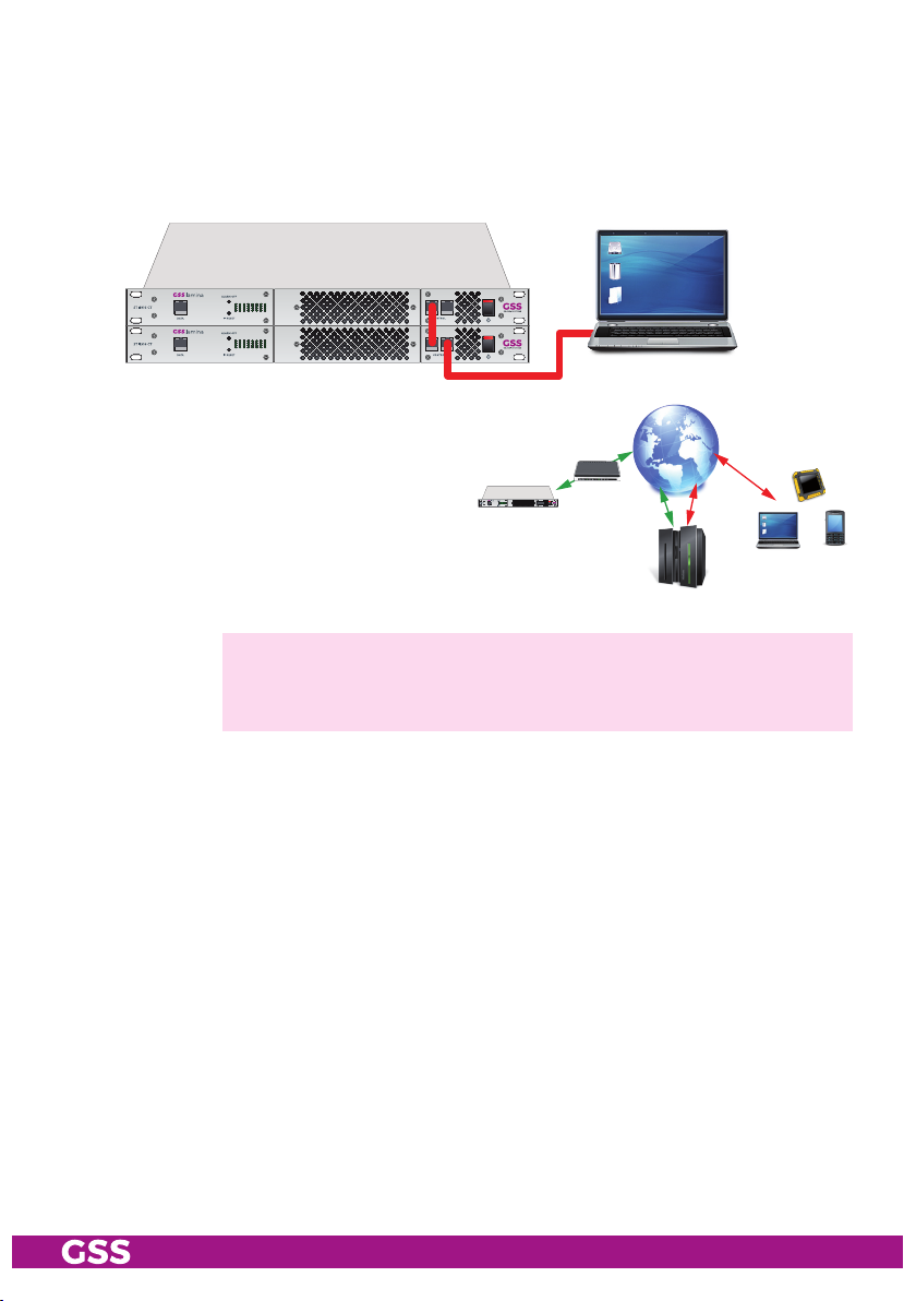
The configuration of the station is to be done via an HTML user interface via a
PC and a standard HTML browser connected to the configuration input.
The two configuration inputs are connected via an internal switch. Several sta-
tions can thus be cascaded for configuration.
If the Control input is connected to
the Internet, after the initial setup,
you can get worldwide access to the
station via an OpenVPN connection
– by PC, tablet or smart phone with
Internet access.
—> When using mobile terminals – dependent on your mobile contract
– additional connection costs / data transfer costs may also be
incurred here.
GSS
OpenVPN
Server
16 LEDs provide an indication of the status of the 16 lines based on their col-
our and indicate if the respective modulator is switched on (LED illuminates) or
off. The LEDs are blinking red/green during data overflow.
The station is powered by two independent power supplies (redundancy). The
power supplies can be replaced individually during operation. If one power
supply unit fails, a warning signal sounds.
If the control input has connection to the Internet, the device can send a warn-
ing e-mail when a signal, power supply or one of the fans fails.
- 7 - STI 1916 CT
Page 8
3 assembly
3.1 deviC e ov erview
7643120 205
1
8
9
16
9 10 11 12
sw rt ge
14 15 1613 14 15 1613 1719
1
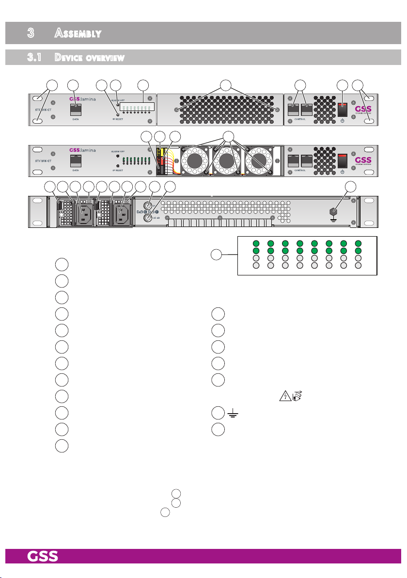
MPTS input lines 1-16
3
Reset IP address and password*
4
Alarm tone off
5
Status LEDs of lines 1…16**
7
LAN socket for configuration
9
GND fan connectors
11
+12 V fan connectors
13
PSU releases
15
IEC connectors C14; connectors for mains cables
16
PSU status LEDs***
18
RF output
20
Mounting support
18
1
5
10
12
14
17
19
9
6
Fan access
8
Power ON/OFF
Fan monitoring connectors
Fan screws
PSU brackets
Connector for potential equalisation
Test output –25dB
8
8
16
* Reset IP address/password to 192.168.0.120/geheim (hold depressed for more than 5
** Green = good signal; rot = no signal; red/green blinking; off = modulator off
*** Power off + no fault –> LED 16 blinks green
Power on + no fault –> LED 16 lights green
Power on + fault –> LED 16 blinks red
- 8 - STI 1916 CT
seconds)
Page 9
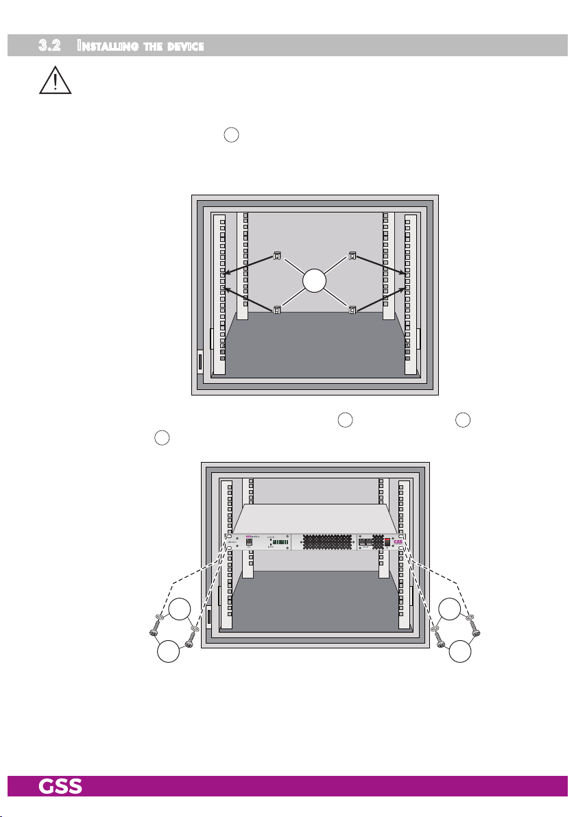
3.2 installi ng the d e viCe
– The device should only be installed in a room where the permissible ambi-
ent temperature range (0 °C … +50 °C ) can be maintained, even during
fluctuations in climatic conditions.
• Attach four cage nuts 22 at the installation site.
We recommend the use of lateral slide rails/component carriers in order to
relieve the front panel.
22
• Screw the unit with the mounting screws 24 and the washer 23 to the four
cage nuts 22.
2323
2424
- 9 - STI 1916 CT
Page 10
3.3 Po t entia l equ a lisation (Pe)
Equalise the potential (PE) in accordance with IEC/EN/DIN EN 60728.
•
Connect the PE connection terminal 17 to a PE rail (supplied by customer)
using the PE wire (Cu 4 mm2 - 9 mm2).
3.4 Con neCting the d e v iCe
• Connect the MPTS input 1 to the LAN network via CAT-6 cables.
—>
The device requests the required multicast IP streams via the MPTS input every 60 seconds. Querier requests will not be answered! Keep
this in mind when configuring the network (querier host timeout).
—> Service Information IGMP Configuration GS2210.
• Connect the attached mains cables to the IEC connectors C14 15.
—> The power cables are equipped with lockable C13 connectors. Re-
move the connectors by pulling back the red locking pin.
• Connect the mains cables to a mains sockets with protective conductor connections. Thereby note the voltage specified on the device.
—> This device has no primary power switch and is in standby mode im-
mediately after connecting the operating voltage. Power ON/OFF
8
switches only the secondary DC voltages!
For a complete disconnection from the mains, both mains plugs must
be pulled out of the mains sockets. Ensure that the mains plugs can
be pulled out without difficulties.
• Configure the device (page 13).
• If the configuration is finished connect the RF output 18 to the cable network.
- 10 - STI 1916 CT
Page 11
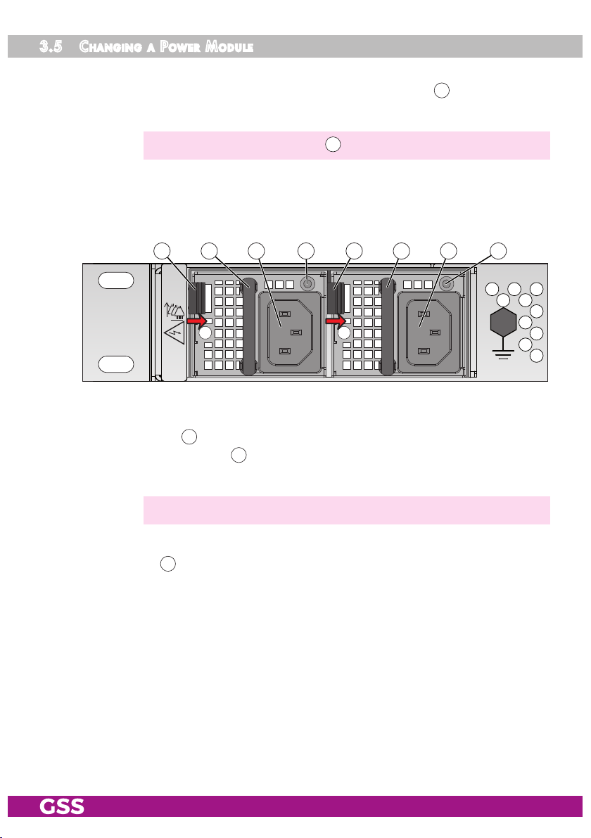
3.5 Cha nging a Pow e r modu le
In case of a malfunction of a power module – or if only one mains cable is
connected – a warning signal sounds and the status LED 16 blinks red if the
set is switched on.
—>
Using button "ALARM OFF" 4 the warning signal can be switched off.
A warning e-mail will be sent out if a connection from the CONTROL input to
the Internet is established and warning e-mails are configured in the device
settings.
14 15 1613 14 15 1613
sources
Separate
all power
Caution!
Dangerous
voltage!
A defective power module can be exchanged during operation.
• Remove the mains cable from the defective power module.
• Move release 13 in direction of the arrow and pull the power module out of
the device by bracket 14.
• Insert the new power module.
—> Make sure that it is locked.
• Connect the new power module to the mains cable and check whether the
status LED 16 lights green.
- 11 - STI 1916 CT
Page 12
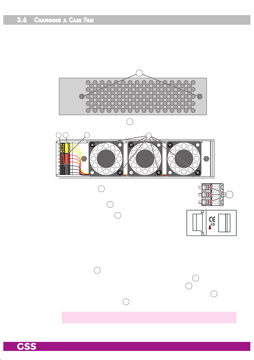
3.6 Cha nging a Case fan
If a connection from the CONTROL input to the Internet is established and
warning e-mails are configured in the device settings, a warning e-mail will be
sent out in case of a case fan malfunction.
A defective case fan can be exchanged during operation.
6
• Remove the fan panel (2 screws 6).
9 10 11
sw rt ge
12
• Remove the 2 screws 12 of the defective fan.
• Remove the wires of the defective fan from the connection
terminals (pressure point 21).
21
• Mount the new fan (screws 12). An arrow on the fan
housing indicates the flow direction. Mount the fan so
that the air stream is passed into the device.
• Shorten if necessary connecting cables in accordance. The cable ends must be stripped 6…7mm.
• Push the connecting cables in the space between the fan and case ground.
• Attach the stripped ends of the connecting wires to the appropriate terminals (pressure point 21):
– the black wire to the lower terminal (3 x minus terminal 9).
– the red wire to the middle terminal (3 x plus terminal 11).
– the yellow wire on the upper terminal (3 x monitoring terminal 10).
• Mount the fan panel (2 screws 6).
—> Make sure that no wires will be clamped between fan and housing.
- 12 - STI 1916 CT
Page 13
4 Configuration / uPdates
The configuration of the STI 1916 CT is to be done via an HTML user interface
via a PC and a standard HTML browser.
4.1 init ial C o n figurat i on
• Connect a PC via a LAN cable directly to a configuration input 7.
—> The PC and the head-end station must be within the same network
(same IP address range). Cookies must be accepted an JavaScript
must be active.
Use current browser versions.
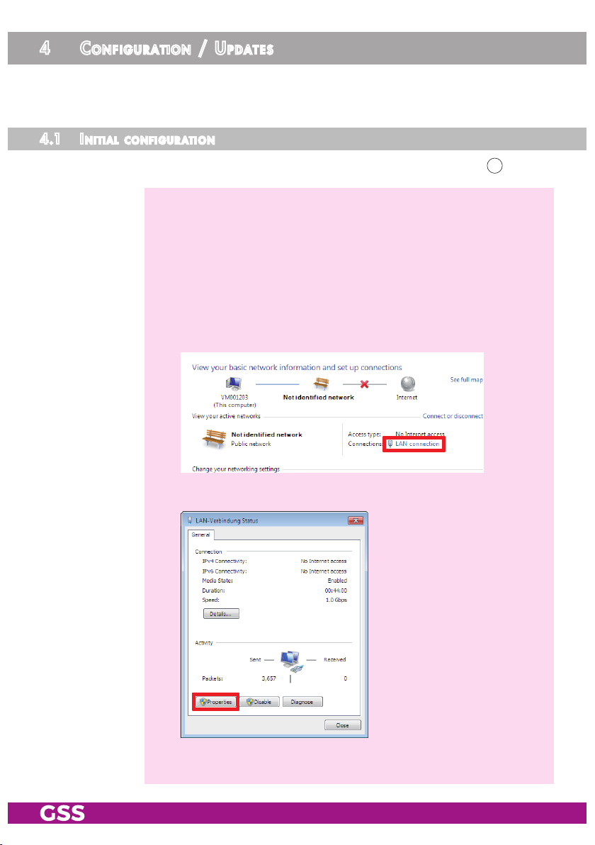
—> Example for IP address setting with Windows 7 operating system:
• For the initial setup open the properties for TCP/IPv4 of the PC:
> Control Panel
> Network and Sharing Center
> LAN connection
> Properties
- 13 - STI 1916 CT
Page 14

> Internet Protocol Version 4 (TCP/IPv4)
> Properties
• Activate point "Use the following IP address".
• Enter e.g. 192.168.0.2 for the IP address.
• Enter for the Subnet mask 255.255.255.0.
• Confirm the setting with "OK".
- 14 - STI 1916 CT
Page 15

• Start the browser, enter the IP address of the device (factory default is
192.168.0.120) and start the establishment of the connection.
• Enter user "admin" and your Password and click on button "Login".
The default password is "geheim".
—> For further logins observe the menus System > Network and System
> OpenVPN!
—> The Overview window is displayed.
First, an "empty" table is displayed (as with all menus). While the
data is read from the device ...
… is displayed.
—> Changes in the menus are only transmitted to the head-end station
when you click the button!
- 15 - STI 1916 CT
Page 16

4.2 Con figurat i on
overv iew wi nd ow
38
34
35
37
30
31
32
33
36
39
40
41
30
Via the selection System you have access to the menus of the System set-
42
tings: Logbook (page 31); Network (page 32); OpenVPN (page 33); Security
(page 34); E-Mail (page 35); Firmware (page 37); User (page 39)
31
In all menus you will return to the Overview via the button Overview.
32
Via the selection Configuration you have access to the menus of the Con-
figuration settings: Input (page 18); Output (page 19); NIT (page 23); Filter
(page 23); LCN (page 29).
33
Herein the installed firmware version is displayed.
34
This location text can be modified arbitrary in menu System/User.
—> If you remote control head-end station at different locations, herein
you can enter the location and a local contact person.
35
Select menu language (English/German)
36
Herein the current system temperature as well as date and time of the last
login is displayed.
—> If a system temperature of 85°C will be reached, the system will be
shut down..
- 16 - STI 1916 CT
Page 17

37
Via button Logout you can leave the graphical user interface.
38
Via the Help menu you can call up the assembly instructions (PDF) as well
as a ZIP file containing a list and all licences of the used OpenSource
software.
39
Overview of the transponder set, with output frequency, TS-/ON ID, Multicast address and data rate. Via the background colour of column Line you
are informed about the quality of the input signals ( good/ no signal),
a possible exceeding the output data rate ( ), or whether the output is
switched off ( ).
—> If in menu Configuration/Input (page 18) transponder names are
NOT assigned, the name of the first station of each transponder is
displayed.
40
Hardware monitoring; shows the state of the power supplies and the fans
41
Via button Download a configuration protocol can be stored as text file
resp. opened using a text editor.
—> From this protocol file e.g. a list of the programmed stations can be
prepared using e.g. a text editor.
42
Herein notes are displayed, which you can enter in menu System/User.
Perfo r m Change s
Before leaving a menu, changes must be transmitted to the head-end station.
• Therefore click on button .
After that is displayed for a short time in the upper right corner.
number format
For entering/indication of the different IDs the number format can be set to
hexadecimal or decimal in menu System > Firmware.
- 17 - STI 1916 CT
Page 18

Confi gur at ion men us
inPut
50 51 52 53 54
55
—> Via the background colour of column Line you are informed about
the quality of the input signals ( good/ no signal), a possible exceeding the output data rate ( ), or whether the output is
switched off ( ).
50
In column Input you can deactivate the input of not used lines. This pre-
vents unwanted/unnecessary data traffic on the network.
51
In column Name, you can enter a personal transponder name
—> If you delete a transponder name, the name of the first station of
this data stream is entered. If the data stream will be changed, the
transponder name will NOT be changed automatically!
52
In the IP Address column, type the multicast IP address of the IP stream
that you want to receive.
53
In the Port column, type the port to the multicast IP address of the IP
stream.
54
- 18 - STI 1916 CT
The TS and ON IDs of the stream are displayed in the TS / ON ID column.
Page 19

55
Before leaving the menu, changes must be transferred to the head-end
station!
• Therefore click on button .
—>
After that is displayed for a short time in the upper right corner.
outPu t
By default QAM modulation is set for the output. If you would like to use
COFDM at the output, first you have to select COFDM for the output setting in
menu System > Firmware and confirm with button . The station restarts!
DVB-C/QAM DVB-T/COFDM
5857 59 60 62 61 66
68
57
67
—> Via the background colour of column Line you are informed about
the quality of the input signals ( good/ no signal), a possible
exceeding the output data rate ( ), or whether the modulator is
switched off ( ).
68
The upper value shows the current needed data rate.
61595857 62 63 64 65 66
67
The lower value shows the maximum possible output data rate (depend-
ant on the output settings).
- 19 - STI 1916 CT
Page 20

—> The background colour in column Line indicates an output data
overflow.
In this case change the output settings or remove stations from the
data stream using the station filter.
58
In column Modulator, switch on or off the modulators of the individual lines.
59
In column Chan. / Freq. [MHz], enter the desired output channel/fre-
quency of the individual lines.
—> Double assignments are indicated by a
warning icon .
—> A output signal is normally transmitted
with a bandwidth of 8 MHz. This means
that you can only use the channel centre frequency of the existing
channel grid in the range of channels C21…C69 (frequency grid
8 MHz). The CCIR channel grid is 7 MHz in the range of the lower
frequency bands (channels C5 … C12). If 8 MHz QAM signal
packages are transmitted in these channel ranges, this will result in
interference (overlapping) and transmission problems.
For programming in these channel ranges and in the frequency rang-
es below them, we recommend starting with frequency 306 MHz
going back in steps of 8 MHz (see frequency table on page 40).
Please note thereby that many receivers cannot receive the channel
ranges S21…S41 (306 … 466 MHz).
60
Only if the RF output is set to QAM (page 37):
In column SR [kS/s], enter the desired output symbol rate of the individual
lines.
—> The background colour in column Line indicates an output data
overflow.
In this case increase the output symbol rate or the QAM modulation
or remove stations from the data stream using the station filter.
61
For exceptional cases and "older" digital cable receivers, in column
Spectrum the spectral position of the user signal can be inverted (invers).
Factory default is "normal".
- 20 - STI 1916 CT
Page 21

62
In column Modulation, select the desired kind of modulation of the indi-
vidual lines:
For QAM: QAM 16, 32, 64, 128, 256
For COFDM: QPSK, 16 QAM, 64 QAM
—> The background colour in column Line indicates an output data
overflow.
from the data stream using the station filter.
—> COFDM: SAT transponders can transmit higher data rates than
DVB-T transponders. If complete SAT transponders are present as
MPTS data streams at the input, you must remove services from the
data stream via the "Filter" menu!
63
Only if the RF output is set to COFDM (page 37):
In this case change the output settings or remove stations
Setting of the Code rate - column CR
During a transmission data can be lost or changed. To recover this data
redundancy is added to the signal to be transmitted (forward error cor-
rection). The factor of the quantity of redundancy contained in the bits
transmitted is called code rate.
Using the setting "C7/8" you can get the highest output data rate at low-
est redundancy.
64
Only if the RF output is set to COFDM (page 37):
Setting of the Guard interval - column GI
In this column you set the relation of the duration of the user symbols to
the duration of the guard intervals to be transmitted. A high guard interval, e.g. "G1/4" causes a low output data rate. For cable networks the
setting "G1/32" is adequate.
65
Only if the RF output is set to COFDM (page 37):
Setting of the Bandwidth - column BW
To transmit the output signal in the channel range of S21 to C69 a band-
width of 8 MHz can be used.
In the channel range of C5 to C12 a bandwidth of ≤7 MHz must be set.
66
In column Level [dB], balance the output levels of the different lines
(0…-10dB). Therefore measure and note down the output level of each
modulator. Adjust the higher output levels to the output level of the modulator with the lowest output level incrementally.
—> Changes must be transmitted to the head-end station!
Therefore click on button .
- 21 - STI 1916 CT
Page 22

67
Balance here the master output level of the station to the level of the ca-
ble network (0…-31dB; off).
0dB = unchanged level; -31dB = 31dB attenuation
off = Level 0 (no output signal)
—> Changes must be transmitted to the head-end station!
Therefore click on button .
68
Before leaving the menu, changes must be transferred to the head-end
station!
• Therefore click on button .
—>
After that is displayed for a short time in the upper right corner.
- 22 - STI 1916 CT
Page 23

nit
73
74
75
82
70
71
72
80
—> Modulators switched off are indicated:
70
Herein you can change the Network ID.
—> For entering/indication of the different IDs the number format can
be set to hexadecimal or decimal in menu System > Firmware.
71
Herein you can enter a NIT version.
—> The maximum possible value is 1F/31.
72
Herein you can enter a network name.
73
Button Load resets the network ID, the version and the network name to
81
79787776
default.
74
Herein you get an overview of the transponders, which are included in
the NIT. If changes are done in menu output after preparing the NIT, an
error and in column Line a "–" will be indicated.
- 23 - STI 1916 CT
Page 24

In column Options the button for Edit and Delete are displayed, if
transponders are added manually (77/78) or if an error occurs.
Edit a QAM transponder Edit a COFDM transponder
—> If you delete an entry , all related LCNs will also be deleted.
75
- 24 - STI 1916 CT
Create the NIT
—> Manually added (77/78) or imported (80) transponders will not be
deleted.
76
Herein you can delete the NIT as well as the LCNs.
—> Switch off the NIT:
Delete the NIT.
Thus, no NIT is played out on the station!
Page 25

77
Herein you can manually add QAM transponders of
other stations.
—> Double assignments are indicated by a warning
icon .
—> Added transponders of a second station are marked in column Line
by a "–".
—> For entering/indication of the different IDs the number format can
be set to hexadecimal or decimal in menu System > Firmware.
78
Herein you can manually add COFDM transponders of
other stations.
—> Double assignments are indicated by a warning
icon .
—> Added transponders of a second station are
marked in column Line by a "–".
—> For entering/indication of the different IDs the number format can
be set to hexadecimal or decimal in menu System > Firmware.
79
Here you can export the NIT and LCN. You can add these to a second
station or use it as a backup.
80
Herein you can restore a NIT and LCN (from a backup) or e.g. add the
NIT of a second station.
—> The data is added - NOT replaced!
Add NIT and LCN of a second station:
• Click on button Upload 80 and select the backup file (*.bin).
—> You can also add an "*.oni" file, which you had generated with a
PSW 1000 (from version 61 on) or a PSW 160 (from version 17
on).
• In the selection window click on button "Open".
The data is added.
- 25 - STI 1916 CT
Page 26

—> Double assignments of frequencies are display. In this case first elim-
inate the double assignments, and then import the corrected data.
—> Double assignments of LCNs are marked in red in the LCN list.
• Click on button .
—> Added transponders of a second station are marked in column Line
by a "–".
—> Now finally you must export the revised NIT. Then load this file into
the second station like a backup.
Now both stations have identical NITs.
Restore a backup:
• First delete the NIT (76).
—> Thereby the LCNs are also deleted. This ensures that all stations
play out the same NIT and LCN.
• Click on button Upload 80 and select the backup file (*.bin).
• In the selection window click on button "Open".
The data is added.
• Click on button .
81
Before leaving the menu, changes must be transferred to the head-end
station!
• Therefore click on button .
—>
After that is displayed for a short time in the upper right corner.
82
Indication of Code rate, Guard interval, Bandwidth and Mode of COFDM
transponders
- 26 - STI 1916 CT
Page 27

filter
In menu Filter you can re-
move stations (Services) and
PIDs (Drop PIDs) from the data
streams of the transponders
(with adaptation of the tables).
—> For entering/indication of the different IDs the number format can
be set to hexadecimal or decimal in menu System > Firmware.
90
Select displaying the station filter.
91
Herein you can select whether only one line is displayed or all lines are
displayed.
90
91
92
93
94
95
99
100
96
97 98
92
Indication of current (used) and maximum (max) output data rate of the
transponder.
93
In column Filter you can individually switch on or off the filter.
94
Indication of TS-/ON-ID.
95
In column Pass Service you select the stations (services) which you would
like to play out.
—> Only if the filter 93 is enabled, services in which the hook has been
removed ( ), are suppressed (filtered out)!
—> If the filter is enabled, new services added to the transponder are
suppressed until a hook is set.
—> The background colour in column Line indicates an output data
overflow.
change the output settings or remove stations from the data stream
using the station filter.
- 27 - STI 1916 CT
In this case check
the values in column used/max 92,
Page 28

—> indicates scrambling.
96
Select displaying the PID filter.
97
Activate the indication of the PID filter by select box "Drop PIDs" 96.
Herein you can remove individual PIDs from the transport stream of each
line.
• Enter the PID to be dropped...
98
... and confirm with "+".
—> After that an additional field appears to enter an additional PID.
—> Therefore also observe the functions
99
Via button Reset, only for the displayed filters (dependent on the selec-
91
and 99.
tions for Typ 90 96 and Overview 91) columns Pass Service 95 and Filter
93
are reset to factory defaults ( and ).
100
Before leaving the menu, changes must be transferred to the head-end
station!
• Therefore click on button .
—>
After that is displayed for a short time in the upper right corner.
- 28 - STI 1916 CT
Page 29

lCn – logiC al Ch annel nu m b ering
110
111
112
115
119
113
114
120
116 117 118
—> Before you can assign LCNs, a NIT must be created or imported.
—> Due to the differentiation of SD LCN and HD LCN it is possible to
assign the same channel number for a channel transmitted in "SD"
and "HD" quality. Suited "HD" receivers will prefer the services in
"HD" quality, "SD" receivers will use the service in "SD" quality.
110
Herein enter the LCNs for "SD" receiving devices.
111
Herein enter the LCNs for "HD" receiving devices (also SD channels).
—> Ensure that the receiving devices support HD LCN error-free. Other-
wise we recommend to use exclusively SD LCNs.
112
Herein you can switch on or off the "Private Data Specifier".s
—> If you use HD-LCN, this must be switched on.
113
"Private Data Specifier" value
—> For "Private Data Specifier" IEC 62216-1 recommends the value
0x00000028. Since there are different international requirements and the function is ultimately dependent upon the devices
used, we can propose only common values here: United Kingdom
0x0000233A, Nordig 0x00000029, France and the European Association of Consumer Electronics Manufacturers 0x00000028.
- 29 - STI 1916 CT
Page 30

114
Bits for LCN data structure
—> For "LCN Data Structure" IEC 62216-1 recommends the value
"10 Bit". Receivers in German speaking regions mainly use this setting. As in some regions (e.g. United Kingdom, Nordig, France etc.)
different regulations exist, observe the country specific guidelines, if
required.
115
Herein you can add services manually.
—> Only TS-/ON-IDs are available which are regis-
tered in the NIT.
—> For entering/indication of the different IDs the
number format can be set to hexadecimal or
decimal in menu System > Firmware.
116
Via this button you can delete all SD-LCNs.
117
Via this button you can delete all HD-LCNs.
118
Via this button you can export LCNs as a ".bin" file
—> The exported file contains the LCNs as well as the NIT.
119
Herein you can import/add a ".bin" file.
—> You can also add an "*.gsl" file, which you had generated with a
PSW 1000 (from version 61 on) or a PSW 160 (from version 17
on).
120
Before leaving the menu, changes must be transferred to the head-end
station!
• Therefore click on button .
—>
After that is displayed for a short time in the upper right corner.
- 30 - STI 1916 CT
Page 31

sy stem m e n us
logbo ok
In the logbook different alerts or
events are displayed. This help
at a possible troubleshooting.
130
Herein you can select
whether only one line is
displayed or all lines are
displayed.
131
Via this button you can clear the logbook.
132
Via this button you can refresh the indication.
—> The logbook is included in the protocol file (page 16)!
130 131 132
- 31 - STI 1916 CT
Page 32

networ k
Herein you customize the IP Addresses, Gate-
ways and Subnet Masks for the configuration
interface and the streaming interface to the local network.
The configuration interface and the streaming
interface must be assigned to different IP address ranges (factory setting 192.168.0.120
and 192.168.20.120)!
Enter a fixed IP address that is not yet assigned
and is out of the DHCP range of the router.
—> If you do not use separate networks for configuration and stream-
ing, leave the configuration port unused! You can access the user
interface via the IP address of the streaming port. In this case, the
streaming port is also used as a configuration port.
—> Write down the IP addresses! Further access to the device is only
possible via this IP addresses.
—> If you have forgotten your IP address, you can reset the network
settings and the password by the reset button (3 page 8)!
—> For remote access it is important to setup a gateway with Internet
access.
—> The MAC address is only displayed for information an can not be
changed.
—> Before leaving the menu, changes must be transferred to the head-
end station! Therefore click on button .
—>
After that is displayed for a short time in the upper right corner.
—>
The device requests the required multicast IP streams via the Streaming Interface every 60 seconds. Querier requests will not be an-
swered! Keep this in mind when configuring the network (querier
host timeout).
- 32 - STI 1916 CT
Page 33

oPenvPn
Via our VPN server you can get worldwide access to the head-end station by
an OpenVPN connection. Since the connection is made through our server,
you do not need a fixed external IP address or a dynamic DNS access.
—> In order that the OpenVPN connection works the following require-
ments must be fulfilled:
– Your PC must have access to the Internet.
–
The configuration interface must have access to the Internet (already at the
system start).
– The outgoing TCP Port 1194 must be opened (e.g. at the router).
• Open menu System > OpenVPN.
• Copy the "Private Link" http://… into the address line of your browser and
store it as favourite.
• As there is no Internet connection at the system start for the initial configuration, you need to reboot the device after configuration (System> Firmware>
Restart).
—> If there is no Internet connection at the system start, the OpenVPN
service is deactivated temporarily.
—> The Private Link is also included in the protocol file (page 16)!
—> Via the ON/OFF button you can deactivate the OpenVPN service.
—> Before leaving the menu, changes must be transferred to the head-
end station! Therefore click on button .
—>
After that is displayed for a short time in the upper right corner.
- 33 - STI 1916 CT
Page 34

seCur it y
Herein replace the default password geheim by a password of your choice.
—> We strongly recommend that you change the default password to
prevent unauthorized access to the station.
• For authorisation enter the "old" password and after that the "new" password twice.
—> Before leaving the menu, changes must be transferred to the head-
end station! Therefore click on button .
—>
After that is displayed for a short time in the upper right corner.
—> If you have forgotten your password, you can reset the network set-
tings and the password by the reset button (3 page 8)!
- 34 - STI 1916 CT
Page 35

e-m ail
If you would like to receive error messages (e.g. at a defective PSU or fan, or a
missing input signal etc.) via e-mail, herein enter the access data of the outgoing mail server of your e-mail account. Then the e-mail is sent via the outgoing
mail server of your e-mail account to the incoming mail server of this account.
—> Therefor the configuration interface must have access to the Internet.
140
141
142
143
144
145
146
140
Herein enter the e-mail address to transmit and receive the e-mail.
141
Herein enter the password for the outgoing mail server of your e-mail account.
142
Herein enter the outgoing mail server of your e-mail account.
143
Herein enter the port of the outgoing mail server of your e-mail account.
144
Herein select the e-mail encryption which is supported from your e-mail
provider:
– "TLS/STARTTLS" (usually Port 587) or
– "SSL" (usually Port 465)
145
- 35 - STI 1916 CT
Via button send alarm mail you can send a test mail.
—> Before you can send a test mail, changes must be transferred to the
head-end station! Therefore click on button .
Page 36

—> Example:
—> In order to prevent you (e. g. in case of changing reception condi-
tions) from being flooded with e-mails, the function is blocked for 1
hour after sending an e-mail. The lock can be removed by deleting
the logbook.
—> In the e-mail, the contact details, which are stored in menu System >
User are displayed to identify the head-end station.
146
Before leaving the menu, changes must be transferred to the head-end
station!
• Therefore click on button .
—>
After that is displayed for a short time in the upper right corner.
- 36 - STI 1916 CT
Page 37

firmware
Herein select the output modulation QAM or COFDM, time zone, automatic
daylight saving time and the number format (hexadecimal/decimal). In addition a firmware update, backup, factory reset as well as a system restart
(warm start) can be done.
150
151
152
155
156
158
153
154
157
159
160
- out Put mo d u l ati on of he a d-end sta tion:
150
Herein select the kind of output modulation for the whole head-end sta-
tion – QAM or COFDM …
—> By default QAM modulation is set for the output.
… and confirm a change in the output modulation by button
—>
The station restarts!
151
.
- syste m set ti ngs:
152
Herein select the time zone setting dependent on the location of the head-
end station. The head-end station receives the Coordinated Universal
Time – UTC if the configuration input has a connection to the Internet.
Enter the corresponding UTC offset.
- 37 - STI 1916 CT
Page 38

—> Herein the "standard" or "wintertime" must be set.
—> In order e.g. to adjust the Central European Time – CET, the offset
must be set to +1 hour.
153
Herein you can switch off or on the automatic daylight savings time (DST).
154
Herein you can select the number format for entering/indication the dif-
ferent transport stream IDs (hexadecimal/decimal).
155
Before leaving the menu, changes must be transferred to the head-end
station!
• Therefore click on button .
—>
After that is displayed for a short time in the upper right corner.
- fi r mwa re uPdat e:
156
Herein the firmware version of the head-end station is displayed.
• Start the firmware update via button Load firmware update from PC.
• Select the new firmware file in the appearing pop-up menu.
—> Therefor the firmware must be previously stored on your PC. The
current firmware version can be found at "www.mygss.eu".
—> A firmware update may take a long time to complete.
—> Aborting the firmware update or interrupting the power supply dur-
ing the update might in worst case result in a defect of the device!
—> During the update this
warning is displayed.
—> After a successful update, the following message appears:
- 38 - STI 1916 CT
Page 39

- baCkuP:
157
Via button Save settings to PC you can download the settings from the
head-end station as "*.tar" file for backup.
158
Via button Load settings from PC you can restore the settings from a prior
downloaded backup.
- res e t to faC tory d efa ult s:
159
Reset the head-end station to factory defaults via button reset to factory
defaults.
—> All settings but NOT Password and IP address!
—> If you have forgotten your password, you can reset the network set-
tings and the password by the reset button (hold depressed for more
than 5 seconds; 3 page 8)!
- syste m res tart :
160
Via button Reboot you can restart the head-end station (warm start).
user
In section User you can adjust the location-based data that is displayed in the
header of the menus accordingly. If you remotely manage multiple head-end
stations, you know at any time, at which station you just work.
In the Notes field you can enter any text that will be displayed in the overview
as a reference.
—> Before leaving the menu, changes must be transferred to the head-
end station! Therefore click on button .
—>
After that is displayed for a short time in the upper right corner.
- 39 - STI 1916 CT
Page 40

5 Channel and frequenCy tables
Advice for a frequency grid (8 MHz) in the band I/III
Frequenz
Frequency
42.00
50.00
58.00
66.00
74.00
]
[MHz
Frequenz
Frequency
82.00
114.00
122.00
130.00
138.00
]
[MHz
Frequenz
Frequency
146.00
154.00
162.00
170.00
178.00
]
[MHz
Frequenz
Frequency
186.00
194.00
202.00
210.00
218.00
]
[MHz
Frequenz
Frequency
226.00
234.00
242.00
250.00
258.00
]
[MHz
Frequenz
Frequency
266.00
274.00
282.00
290.00
298.00
]
[MHz
Channel / frequency assinment for DVB-T (band III, frequency grid 7 MHz)
]
Kanal
Channel
Frequenz
Frequency
C 5 177.5
C 6 184.5
C 7 191.5
[MHz
Kanal
C 8 198.5
C 9 205.5
C 10 212.5
Channel
Frequenz
]
[MHz
Frequency
Kanal
Channel
Frequenz
Frequency
C 11 219.5
C 12 226.5
]
[MHz
CCIR – Hyperband (frequency grid 8 MHz)
Kanal
Channel
Kanalmittenfrequenz
Channel centre frequency
S 21 306.00
S 22 314.00
S 23 322.00
S 24 330.00
S 25 338.00
]
[MHz
Kanal
S 26 346.00
S 27 354.00
S 28 362.00
S 29 370.00
]
[MHz
Channel
Kanalmittenfrequenz
Channel centre frequency
Kanal
Channel
Kanalmittenfrequenz
Channel centre frequency
S 30 378.00
S 31 386.00
S 32 394.00
S 33 402.00
]
[MHz
Kanal
Channel
Kanalmittenfrequenz
Channel centre frequency
S 34 410.00
S 35 418.00
S 36 426.00
S 37 434.00
]
[MHz
Kanal
Channel
Kanalmittenfrequenz
Channel centre frequency
S 38 442.00
S 39 450.00
S 40 458.00
S 41 466.00
]
[MHz
CCIR – Band IV/V (frequency grid 8 MHz)
C 21 474.00
C 22 482.00
C 23 490.00
C 24 498.00
C 25 506.00
C 26 514.00
C 27 522.00
C 28 530.00
C 29 538.00
C 30 546.00
C 31 554.00
C 32 562.00
C 33 570.00
C 34 578.00
C 35 586.00
C 36 594.00
C 37 602.00
C 38 610.00
C 39 618.00
C 40 626.00
C 41 634.00
C 42 642.00
C 43 650.00
C 44 658.00
C 45 666.00
C 46 674.00
C 47 682.00
C 48 690.00
C 49 698.00
C 50 706.00
C 51 714.00
C 52 722.00
C 53 730.00
C 54 738.00
C 55 746.00
C 56 754.00
C 57 762.00
C 58 770.00
C 59 778.00
C 60 786.00
C 61 794.00
C 62 802.00
C 63 810.00
C 64 818.00
C 65 826.00
C 66 834.00
C 67 842.00
C 68 850.00
C 69 858.00
- 40 - STI 1916 CT
Page 41

Declaration of CE conformity
GSS Grundig Systems GmbH • Beuthener Straße 43 • D-90471 Nuremberg
Phone: +49 (0) 911 / 703 8877 • Fax: +49 (0) 911 / 703 9210
www.gss.de/en • info@gss.de
KLASSEKLASSE
CLASSCLASS
Service: Phone: +49 (0) 911/703 2221; Fax: +49 (0) 911/703 2326; service@gss.de
Alterations reserved. Technical data E. & O.E. © by GSS Grundig Systems GmbH V14/003/2017
 Loading...