

GSS PTIS Assembly Instructions Manual

Grundig SAT SystEms
GSS
Grundig SAT Systems GmbH
Beuthener Strasse 43
D-90471 Nuremberg
Phone: +49 (0) 911 / 703 8877
Fax: +49 (0) 911 / 703 9210
E-mail: info@gss.de
Internet: http://www.gss.de
Assembly Instructions
Assembly Instructions
English
A
A
CLASS
CLASS
KLASSE
KLASSE
PTIS 1000
Head-End DVB-T Converter to IP
DVB-T to SPTS

- 2 -
- 2 -
Contents
1 Safety regulations and notes .....................................................................................4
2 General information .................................................................................................5
2.1 Packing contents ..........................................................................................5
2.2 Meaning of the symbols used ........................................................................5
2.3 Technical data .............................................................................................5
2.4 Description .................................................................................................6
2.5 Software query ............................................................................................7
3 Assembly .................................................................................................................8
3.1 Installing the cassette ....................................................................................8
3.2 EMC regulations ..........................................................................................8
3.3 Overview of the cassette ..............................................................................9
3.4 Connecting the cassette ..............................................................................10
3.5 Updating the software ................................................................................10
3.6 Retrofitting a CA module ............................................................................11
4 The control panel at a glance ..................................................................................12
4.1 Menu items ...............................................................................................12
4.2 Control panel ............................................................................................12
5 Programming .........................................................................................................13
5.1
Programming procedure
..............................................................................13
5.1.1 Channel strips “Tuner A” (without CA module) and “Tuner B” ................13
5.1.2 Channel strip “Tuner A” with CA module ............................................15
5.2 Programming the cassette ..........................................................................16
Selecting the cassette, displaying the software version ....................................16
Setting the Ethernet parameters ...................................................................17
Setting the IP address of the cassette ............................................................17
Setting the address range ...........................................................................18
Setting the address of the gateway ..............................................................19
Setting the UDP port ...................................................................................19
Selecting the input transport stream ..............................................................20
Setting the input channel ............................................................................20
Setting the hierarchical modulation ..............................................................22
Allocating the IP addresses .........................................................................23
Switching the IP address off or on ................................................................24
Selecting the transmission protocol ...............................................................24
Setting the port number ..............................................................................24
Copying the settings to all IP addresses ........................................................25
Defining the quantity of data packets ...........................................................25
Setting the forward error correction .............................................................25
Setting the transmission channel ..................................................................25
Copying the settings to all IP addresses ........................................................26
Setting IP addresses for services ..................................................................27
Allocating IP addresses to services manually .................................................27
Allocating IP addresses to services automatically ...........................................27

- 3 -
- 3 -
Allocating services manually .......................................................................28
Selecting the sound options of the service .....................................................29
Switching DVB service information on or off ..................................................30
Copying the settings to all IP addresses ........................................................30
Displaying the output data rate ....................................................................31
Saving settings ..........................................................................................31
5.2.1 Operation with a CA module ............................................................31
Setting the operating voltage for the CA module .................................31
Setting the PID monitoring ................................................................32
Configuring the CA module ..............................................................33
Decoding services ...........................................................................34
6 Final procedures .....................................................................................................35
- 4 -
- 4 -
1 Safety regulations and notes
• Assembly, installation and servicing should be carried out by authorised
electricians.
• Switch off the operating voltage of the system before beginning with assembly or service work or pull out the mains plug.
• Do not perform installation and service work during thunderstorms.
• Install the system so it will not be able to vibrate…
- in a dust-free, dry environment
- in such a manner that it is protected from moisture, fumes, splashing
water and dampness
- somewhere protected from direct sunlight
- not within the immediate vicinity of heat sources
- in an ambient temperature of -20 °C to +50 °C.
• Ensure that the head-end station is adequately ventilated. Do not cover
the ventilation slots.
• Beware of short circuits
• No liability is accepted for any damage caused by faulty connections or
inappropriate handling.
• Observe the relevant standards, regulations and guidelines on the instal-
lation and operation of antenna systems.
• Earth the receiving system in accordance with DIN EN 50083-1 / 60728-
11 and VDE 0855 (earthing, equipotential bonding rail).
• Test the software versions of the head-end station and the cassette and
update them if necessary. The current software versions can be found at
”www.gss.de”.
• For further information please read the assembly instructions for the
head-end station used.
Take action to prevent static discharge when working on the device.
Electronic devices should never be disposed of in the household rubbish. In
accordance with directive 2002/96/EC of the European Parliament and
the European Council from January 27, 2003 which addresses old electronic and electrical devices, such devices must be disposed of at a designated collection facility. At the end of its service life, please take your
device to one of these public collection facilities for proper disposal.

- 5 -
- 5 -
2 General information
2.1 Packing contents
1 Cassette PTIS 1000 2 HF cables
1 CD (assembly instructions) 1 Brief assembly instructions
1 Measuring log
2.2 Meaning of the symbols used
Important note
—> General note
• Performing works
2.3 Technical data
The devices meet the following EU directives:
2006/95/EC, 2004/108/EC
The product fulfils the guidelines and standards for CE labelling.
HF input
Channels: C05 … C12, C21 … C69
Frequency range: 177.5 … 226.5, 474 … 858 MHz
Input level: 60 dBµV … 80 dBµV
Return loss: > 8 dB
Impedance: 75 Ω
Symbol rate acc. to EN 300744
LAN interface
Standard: 100-BASE-T
Data rate: ≤ 80 MBit
Protocols: UDP (User Data Protocol),
RTP (Real-Time Transport Protocol)
ASI interfaces
Standard: DIN EN 50083-9
Format: MPEG ISO IEC 13818-1
User data rate: 2 … 90 Mbit/s
Impedance: 75 Ω
- 6 -
- 6 -
Level (input / output): 800 mVpp ± 10%
Return loss (input): > 17 dB (5 … 270 MHz
Connections
HF inputs: 2 IEC sockets
HF loop-through outputs: 2 IEC sockets
HF output: 1 IEC socket (no function)
LAN: 1 RJ 45 socket
ASI input: 1 BNC socket
ASI output: 1 BNC socket
Connection strip (10-pin): for supply voltages and control circuits
RS 232 socket: serial interface for software update
Common Interface: 1 (several services can be decoded.
2.4 Description
The cassette is a
DVB-T / SPTS
converter which combines COFDM-modulated
services (programmes) and transport streams supplied via the ASI interface
into one transport stream in the TPS module. This is emitted via the LAN interface and can contain up to 16 services. For operating the cassette in a LAN
network it can be assigned its own IP address. The cassette is equipped with
two tuners. The accompanying channel strips consist of the digital tuners and
the digital signal processing levels. The resulting transport streams from the
“
Tuner A
”/“
Tuner B
” channel strips and from the transport streams supplied
via the ASI socket (ASI – Asynchronous Serial Interface according to DIN EN
50083-9) can take up to 16 services and are each assigned an IP address.
The
signal supplied into the ASI input is provided again via the ASI output.
Principle signal path:
TPS
"Tuner A"
"Tuner B"
CA-ModulCA module
ASI input
ASI output
IP address: Port:
Service 1 212.40.90 : 1234
Service 2 212.40.91 : 1234
Service 3 212.40.92 : 1234
Service 4 212.40.93 : 1234
Service 5 212.40.94 : 1234
Service 6 212.40.95 : 1234
Service 7 212.40.96 : 1234
Service 8 212.40.97 : 1234
Service 9 212.40.98 : 1234
Service 16 212.40.105 : 1234

- 7 -
- 7 -
In the head-end station display, the channel strips of the cassette are indicated
with “
Bx …A
” (“
Tuner A
”) or “
Bx …B
” (“
Tuner B
”). The channel strip “
Tuner A
”
can decode encoded services via a corresponding CA module and a dedicated
smart card. The cassette is programmed using the head-end station control unit.
Two LEDs in the channel strips provide an indication with their colour whether
an HF signal is present or not. In a menu, the transmission of DVB service information (EIT, TDT and SDT) or teletext (TXT) can be individually activated or
deactivated.
DVB service information:
EIT (Event Information Table):
For each service, event information is transmitted (such as starting time,
duration, encryption etc.)
TDT (Time Date Table):
The transmitted table contains the current time and date.
SDT (Service Description Table):
Information relating to the encryption is also sent with the name of each
service.
The LEDs for the LAN interface show whether a network connection exists and
whether a data transfer is in progress.
When the head-end station is switched on, the two-line LC display shows the
software version of the control unit. To operate this cassette the software version
of the control unit must be “V 41” or higher. You can find the current operating
software for the control unit and the cassette, the required update software
“BE-Flash” and the current assembly instructions on the website “www.gss.de”.
The cassette is designed for use in the following head-end stations:
– PGT 8 – PST 19-1
– PSU 8 – PSU 12
2.5 Software query
Control unit
If necessary, you can activate the indication of the software version of the control unit manually:
• Press any two keys on the control unit of the head-end station simultaneously
until the display goes dark and the software version, e.g. “V 41” appears.
Cassette
After activating the cassette the software version of the cassette is displayed (s.
page 16).
- 8 -
- 8 -
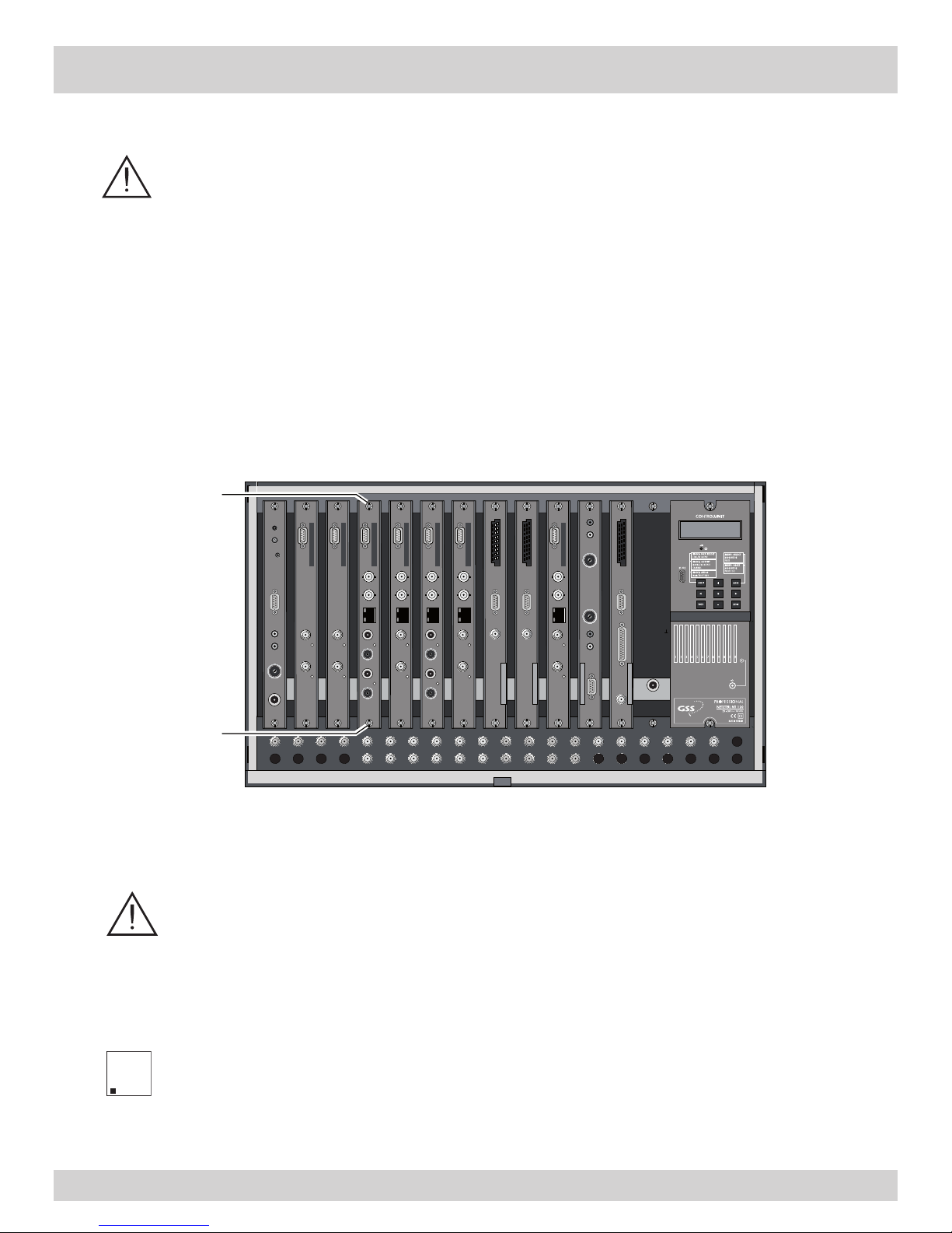
3 Assembly
3.1 Installing the cassette
– Ensure the head-end station is mounted so it will not be able to vibrate.
Avoid, for example, mounting the head-end station onto a lift shaft or any
other wall or floor construction that vibrates in a similar way.
– Before installing or changing a cassette unplug the power cable from the
mains power socket.
• Remove the fastening screws
1 of an unoccupied slot from the bracket of the
head-end station.
• Insert the cassette in this slot and push it into the housing.
• Align the cassette and apply slight pressure to connect it to the connections of
the board and the HF output collector
.
• Fasten the cassette with the screws 1.
3.2 EMC regulations
To comply with the current EMC regulations, it is necessary to connect the
lines leading in and out of the head-end station using cable terminals.
When mounting the cassette in a head-end station which is installed in a
19” cabinet, make sure the connections leading in and out for the 19” cabinet are made using cable terminals.
The attenuation of shielding of the connection lines must meet the require-
ments for “Class A”.
0°
.$66(77(
.$66(77(
.$66(77(
.$66(77(
.$66(77(
.$66(77(
.$66(77(
.$66(77(
.$66(77(
.$66(77(
.$66(77(
.$66(77(
AUSGANG
max. 90 dBμV
ACHTUNG!
Vor dem Kassettenwechsel
unbedingt
denNetzstecker ziehen.
CAUTION!
Before
changing cassettes remove
mains plug.
*UXQGLJ6$76yVWePV
1
1
A
A
CLASS
CLASS
KLASSE
KLASSE
- 9 -
- 9 -
• Insert the required number of cable terminals in the openings provided in the
head-end station or in the 19” cabinet.
—> Cable terminals are not included in the scope of delivery.
Tighten the nuts of the cable terminals until the teeth on the lock washers
put
under
have penetrated the exterior coating and a good connection is made
between the housing
/ 19” cabinet
and cable terminals.
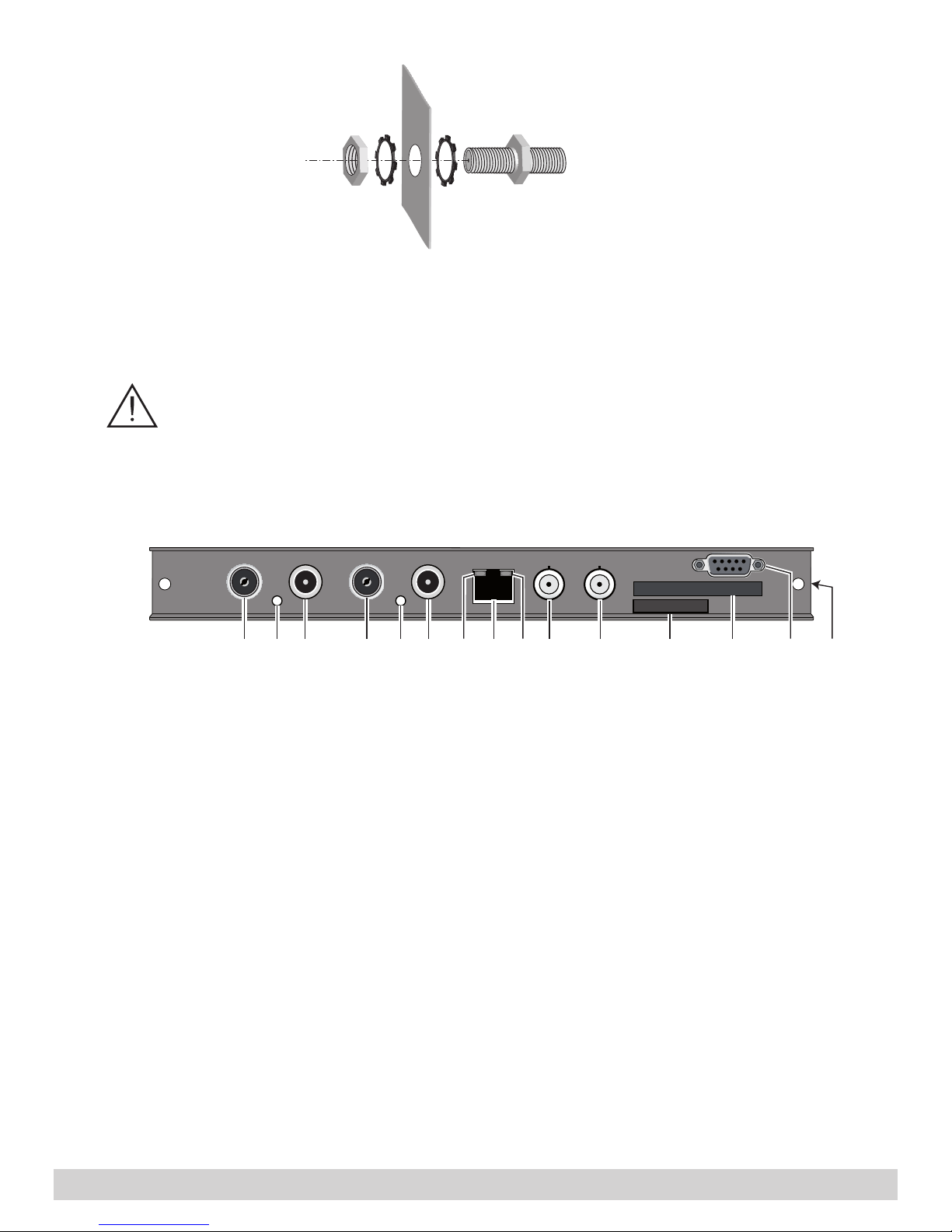
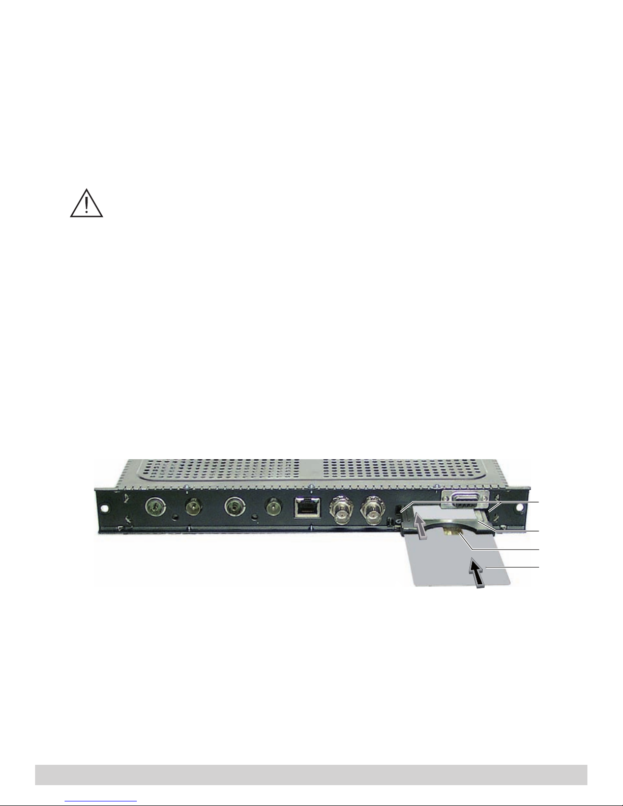
3.3 Overview of the cassette
1 HF input
(channel strip “
Tuner B
”)
2 Status LED
of the channel strip “
Tuner B
”
3
Loop-through output of
HF
input
1
4
HF input
(channel strip “
Tuner A
”)
5 Status LED
of the channel strip “
Tuner A
”
6
Loop-through output of
HF
input
4
7 Status LED of the LAN interface (yellow LED – data transfer)
8
LAN socket
9 Status LED of the LAN interface (green LED – network connection)
0 ASI input
! ASI output
@ Type label
# Slot for a CA module
$ D-SUB socket “RS 232“
% MAC address
7890 ! # $3265 @ %41
- 10 -
- 10 -
3.4 Connecting the cassette
• Connect the HF connections to the inputs
4 (channel strip “
Tuner A
”) and 1
(channel strip “
Tuner B
”).
• Connect the LAN socket 8.
• Connect the ASI input 0 and the ASI output ! to the peripheral ASI devices.
3.5 Updating the software
The RS 232 interface of the cassette $ enables you to use a PC or a notebook
and the “BE-Flash” software to update the software of the cassette.
You can find the “BE-Flash” software and the current operating software of the
cassette at the website
”www.gss.de”
.
• Use a “one-to-one cable” to connect the cassette’s RS 232 interface and the
PC according to the wiring scheme below.
—> If necessary use a standard RS-232/USB adapter.
• Start the “BE-Flash” software and update the software of the cassette.
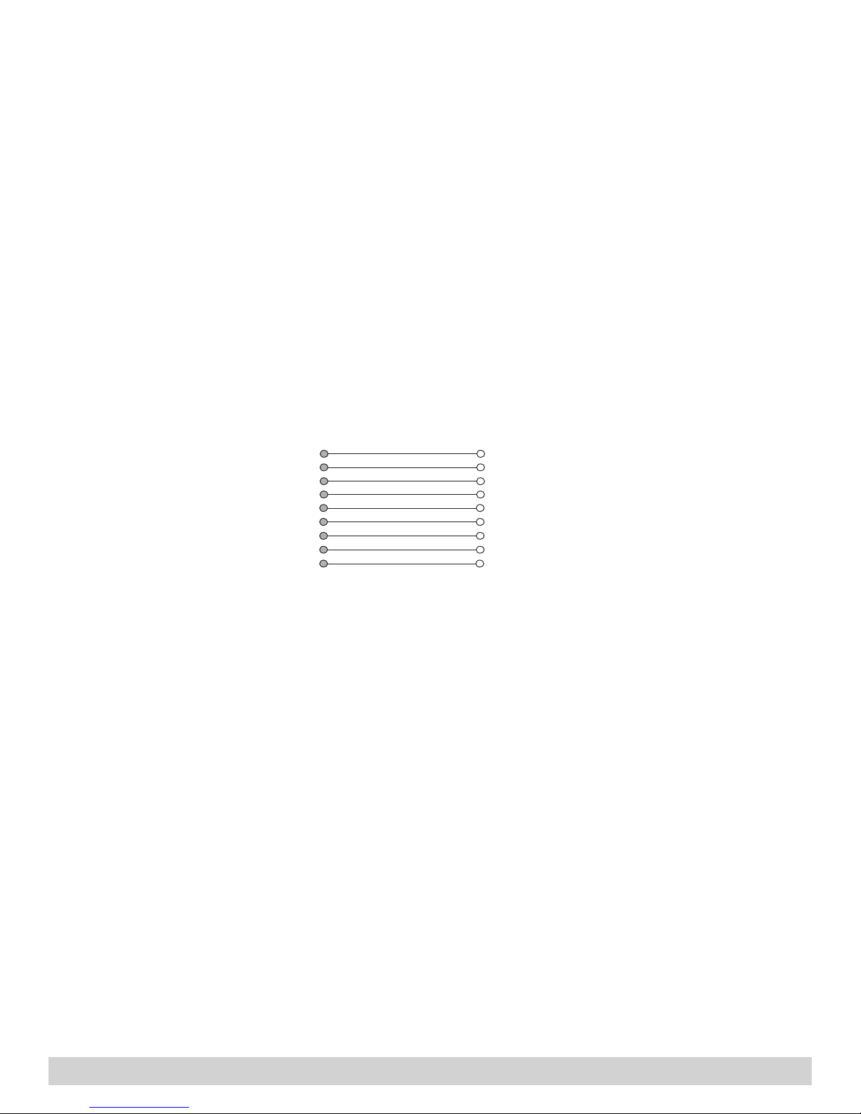
9-pin
D-SUB socket
9-pin
D-SUB plug
1
2
3
4
5
6
7
8
9
1
2
3
4
5
6
7
8
9
- 11 -
- 11 -
3.6 Retrofitting a CA module
The cassette is equipped with a common interface. It allows you to connect a
CA module for various encryption systems and service providers. Encoded services can only be decoded with a CA module suitable for the encoding system
and the corresponding smart card. The smart card contains all the information
for authorisation, decoding and subscription.
– Check with the distributor or manufacturer of the CA module to be
used to ensure that it is suitable for decoding several
services
.
– The hardware and software of this cassette have been thoroughly pre-
pared and tested.
Any changes made by
service
providers in the data structures might im-
pair or even prevent this function.
– When working with the CA module, please read the corresponding op-
erating manual from the respective provider.
• Insert the smart card
1
into the CA module
2
so that the chip
3
on the
smart card faces the thicker side (top) of the CA module.
• Insert the CA module into the guide rails of the CA slot
4 with the top side
of the CA module facing the top side of the cassette.
• Push the CA module without canting into the guide rails of the CA slot
4 and
contact it to the common interface.
3
4
1
2
 Loading...