

GSS PSDP 6200 Assembly Instruction Manual
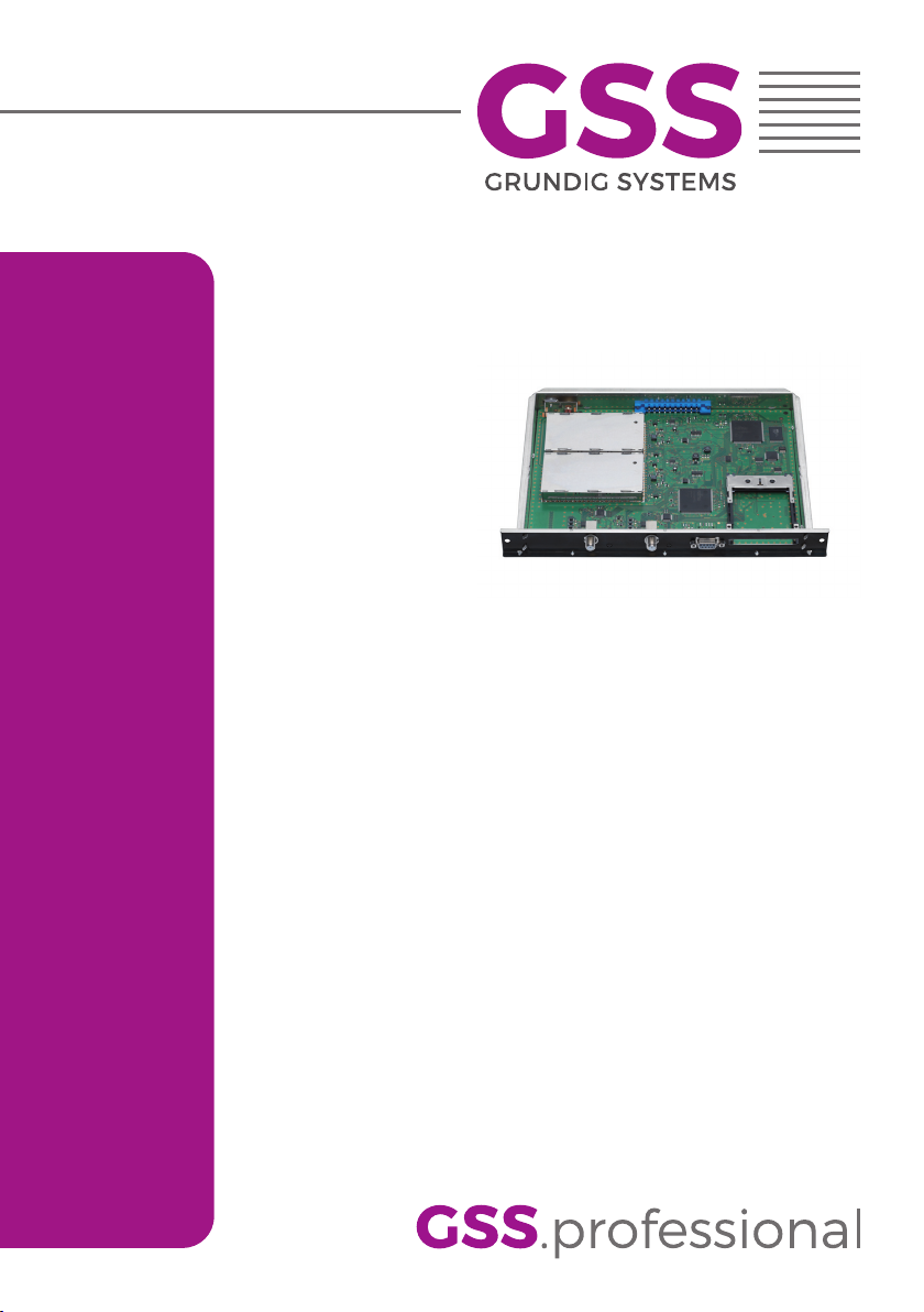
PSDP 6200
Assembly Instruction

Contents
1 Safety regulations and notes ........................................................................4
2 General information ....................................................................................5
2.1 Packing contents ............................................................................5
2.2 Meaning of the symbols used ..........................................................5
2.3 Technical data ...............................................................................5
2.4 Description ...................................................................................6
2.5 Software query..............................................................................7
3 Assembly ....................................................................................................8
3.1 Installing the cassette......................................................................8
3.2 EMC regulations ............................................................................9
3.3 Overview of the cassette ..............................................................10
3.4 Connecting the cassette ................................................................10
3.5 Retrofitting a CA module ..............................................................11
4 The control panel at a glance ..................................................................... 12
4.1 Menu items .................................................................................12
4.2 Control panel ..............................................................................12
5 Programming ............................................................................................ 13
5.1 Preparation .................................................................................13
5.2 Programming procedure ...............................................................13
5.3 Programming the cassette ............................................................17
Selecting the cassette, displaying the software version ......................17
Selecting the channel strip ............................................................18
Selecting channel strip "A" ......................................................18
Selecting channel strip "B" .......................................................18
Switching the modulator off or on ..................................................19
Adjusting the output levels of the channel strips ...............................19
Switching the modulator off or on .............................................19
Adjusting the output levels of the channel strips ..........................19
Setting the TV standard of the output signal ....................................20
Selecting channel / frequency setting .............................................20
Setting the output channel .............................................................21
Setting the fine-tuning ...................................................................21
Setting the output frequency ..........................................................21
Selecting the Tuner (only channel strip B) ........................................22
Setting the LNB oscillator frequency ...............................................23
Configuring the CA module (only channel strip A) ...........................23
Setting the LNB oscillator frequency ..........................................23
- 2 - PSDP 6200

Configuring the CA module (only channel strip A) ......................23
Setting the input symbol rate .........................................................24
Setting the input frequency / Reception quality ................................24
Setting the input frequency .......................................................25
Reception quality ....................................................................25
Channel selection ........................................................................26
Selecting the TV station sound / Setting the volume level ..................27
Selecting the TV station sound ..................................................27
Setting the volume level ...........................................................27
Setting the audio mode / audio output ...........................................27
Setting the audio mode ...........................................................28
Setting the audio output ...........................................................28
Selecting the picture format ...........................................................28
Switching WSS/teletext off or on ...................................................28
Switching WSS off/on ............................................................29
Switching teletext mode off/on .................................................29
Activating test lines ......................................................................29
Locking the regional window ........................................................29
Subtitle settings............................................................................30
Setting teletext subtitle pages ...................................................31
Setting the teletext standard .....................................................31
DVB subtitle ...........................................................................31
Frame suppression ..................................................................31
Setting the time zone and summer time ...........................................32
Setting time-controlled, alternative channels ....................................33
Switching the timer on and off ..................................................33
Setting the duty cycle ..............................................................33
Setting the days of the week ....................................................33
Setting the LNB oscillator frequency (timer) ................................34
Configuring the CA module (timer; only channel strip A) .............34
Setting the input symbol rate (timer) ..........................................35
Setting the input frequency (timer) .............................................35
Channel selection (timer) .........................................................35
Selecting the TV station sound / Setting the volume level (timer) ...36
Saving settings ............................................................................36
6 Final procedures ........................................................................................ 37
7 Channel and frequency tables ....................................................................38
- 3 - PSDP 6200
1 safety regulations and notes
• Assembly, installation and servicing should be carried out by authorised
electricians.
• Switch off the operating voltage of the system before beginning with assembly or service work or pull out the mains plug.
• Do not perform installation and service work during thunderstorms.
• Install the system so it will not be able to vibrate…
- in a dust-free, dry environment
- in such a manner that it is protected from moisture, fumes, splashing wa-
ter and dampness
- somewhere protected from direct sunlight
- not within the immediate vicinity of heat sources
- in an ambient temperature of 0 °C to +50 °C. In case of the formation of
condensation wait until the system is completely dried.
• Ensure that the head-end station is adequately ventilated. Do not cover the
ventilation slots.
• Beware of short circuits
• No liability is accepted for any damage caused by faulty connections or
inappropriate handling.
• Observe the relevant standards, regulations and guidelines on the installation and operation of antenna systems.
• The standards EN/DIN EN 50083 and IEC/EN/DIN EN 60728 must be
observed.
• For further information please read the assembly instructions for the headend station used.
• Test the software versions of the head-end station and the cassette and
update them if necessary. The current software versions can be found at
"www.mygss.eu".
Take action to prevent static discharge when working on the device!
Electronic devices should never be disposed of in the household rubbish. In
accordance with directive 2002/96/EC of the European Parliament and the
European Council from January 27, 2003 which addresses old electronic and
electrical devices, such devices must be disposed of at a designated collection
facility. At the end of its service life, please take your device to one of these
public collection facilities for proper disposal.
- 4 - PSDP 6200
2 general information
2.1 PaCk ing Co ntents
1 cassette PSDP 6200
2 RF cables
1 Brief assembly instructions 1 Measuring log
2.2 meani ng of t h e sym b ols us e d
Important note
—> General note
• Performing works
2.3 teChniCal da ta
The devices meet the following EU directives:
2011/65/EU, 2014/30/EU, 2014/35/EU
The product fulfils the guidelines and standards for CE labelling (page 39).
Unless otherwise noted all values are specified as "typical".
RF input
Frequency range: ....................................................... 950 … 2150 MHz
Level range: ............................................................ 60 dBμV … 80 dBμV
Input impedance: ............................................................................ 75 Ω
Symbol rate: ................................................................1 … 45 Msymb/s
RF output
Channels: .....................................................C2 … C69 (incl. S2 … S41)
Frequency range: ........................................ 48.25 MHz … 855.25 MHz
Standard: ......................................................................... CCIR PAL B/G
Output level: ............................................................................. 98 dBμV
Output level attenuation: ............................................................0 … 7 dB
Output impedance: ......................................................................... 75 Ω
Video interference level: .................................................................57 dB
Video band width: ......................................................... 20 Hz … 5 MHz
Audio interference level: ..............................................................> 50 dB
Audio band width: .........................................................40 Hz … 15 kHz
- 5 - PSDP 6200

Connections
SAT inputs: ............................................................................. 2 F sockets
RF output: ............................................................................ 1 IEC socket
Connection strip (10-pin): ..................for supply voltages and control circuits
RS 232 socket: ..................................... serial interface for software update
Conditional access:...............................1 (2 channels can be descrambled)
2.4 des CriPtion
The twin transmodulator cassette is a QPSK-converter, which converts all sta-
tions modulated according to DVB-S
ed cable signals.
The
cassette
has two digital SAT IF inputs and one RF output.
and
QPSK
standard into two PAL-modulat-
It is equipped with two channel strips. Each channel strip consists of a digital
tuner, a digital signal preparation unit and a modulator. The
strips are indicated by
"Bx …A" or "Bx …B"
in the control unit display.
cassette
‘s channel
The channel strip "A" can descramble scrambled channels via a correspond-
ing CA module. Depending on the CA module and the smart card, two channels can be descrambled simultaneously with one CA module, with the second
one supplied via channel strip "B". Using the integrated time control you can
select alternate channels. The control of the
cassette
takes place via the control
unit of the head-end station.
Two LEDs provide an indication of the SAT IF input signal quality based on
their colour. Additionally the quality of the transport stream received is displayed ("CN…"). If the data of channel strip "A" are used in channel strip "B"
the status LED of channel strip "B" is switched off.
The prepared input signals reach the RF output collector of the head-end sta-
tion via the RF output socket. The common output level of the channel strips can
be set at the RF output collector of the head-end station.
When the head-end station is switched on, the two-line LC display briefly
shows the software version of the control unit. To operate this cassette the
software version of the control unit must be "V 45" or higher. You can find the
current operating software for the control unit and the cassette, the software
"BE-Flash"
The
and the current assembly instructions
cassette is
designed for use in the following head-end stations:
on the website "www.gss.de".
PSU 12, PSU 8-16 and PST 19-1.
- 6 - PSDP 6200

2.5 soft ware q u ery
Control unit
If necessary, you can activate the indication of the software version of the
control unit manually:
• Press any two keys on the control unit of the head-end station simultaneously
until the display goes dark and afterwards
the software version, e.g. "
V 45
appears.
Cassette
After activating the cassette the software version of the cassette is displayed
(see page 17).
"
- 7 - PSDP 6200

3 assembly
3.1 installi ng the C assette
– Ensure the head-end station is mounted so it will not be able to vibrate.
Avoid, for example, mounting the head-end station onto a lift shaft or any
other wall or floor construction that vibrates in a similar way.
– Before installing or changing a cassette unplug the power cable from the
mains power socket.
• Remove the fastening screws 1 of an unoccupied slot from the bracket of
the head-end station.
• Insert the cassette in this slot and push it into the housing.
• Align the cassette and apply slight pressure to connect it to the connections
of the board and the RF bus bar.
• Fasten the cassette with the screws 1.
1
1
- 8 - PSDP 6200
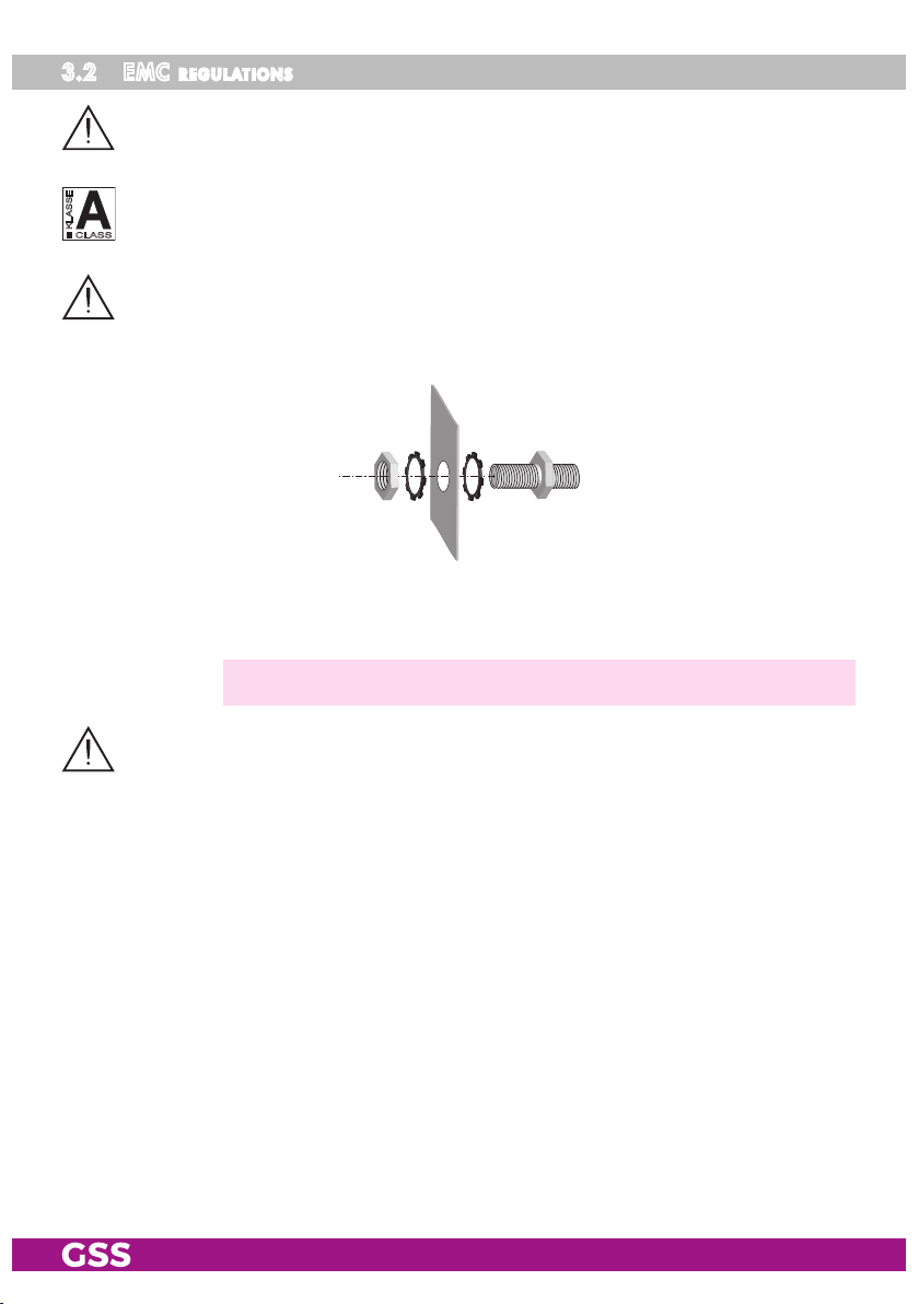
3.2 emC regulations
To comply with the current EMC regulations, it is necessary to connect the lines
leading in and out of the head-end station using cable terminals.
The attenuation of shielding of the connection lines must meet the requirements
KLASSE
for "Class A".
CLASS
When mounting the cassette in a head-end station which is installed in a 19"
cabinet, make sure the connections leading in and out for the 19" cabinet are
made using cable terminals.
• Insert the required number of cable terminals in the openings provided in
the head-end station or in the 19" cabinet.
—> Cable terminals are not included in the scope of delivery.
Tighten the nut on the cable terminal until the teeth on the lock washer have penetrated the exterior coating and a good connection is made between the housing
and cable terminal.
- 9 - PSDP 6200
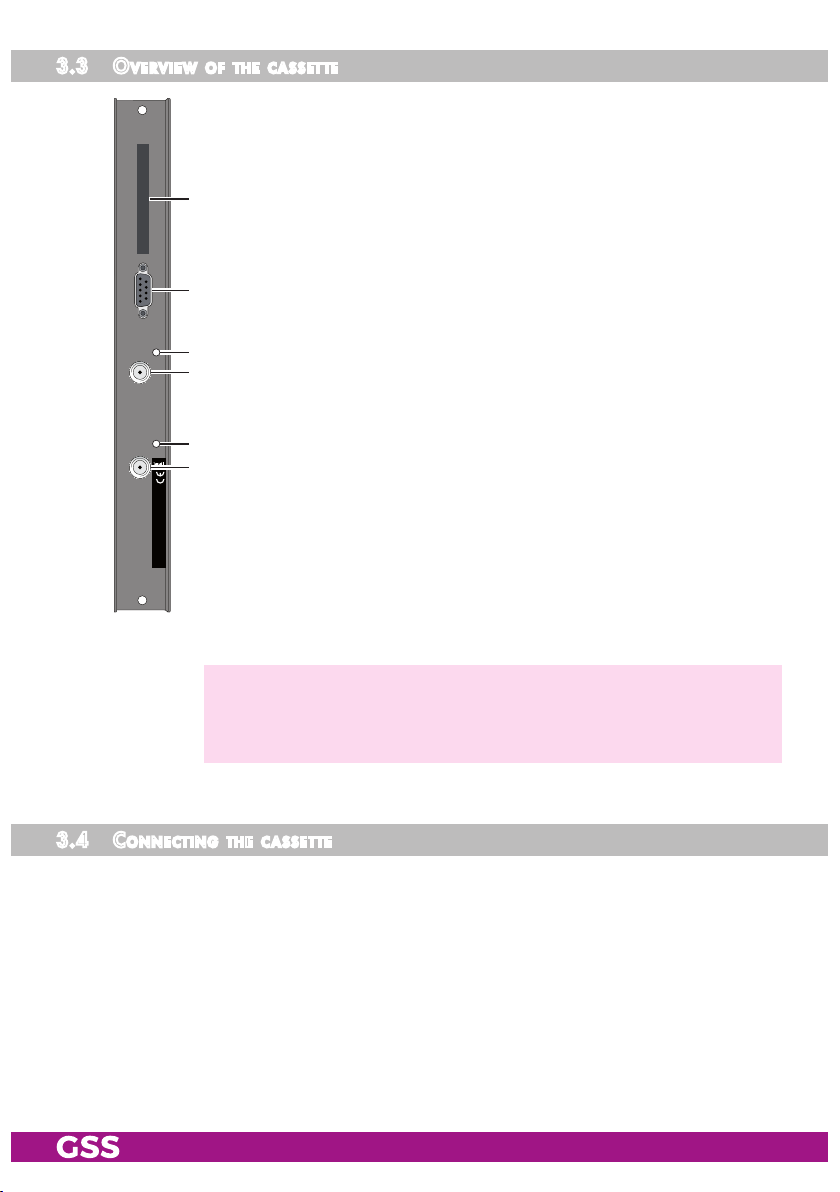
3.3 over v i ew of t he Cas s et te
1 Slot for a CA module
2 D-SUB socket "RS 232"
3 Status LED of the channel strip "A"
4 SAT IF input (channel strip "A")
1
5 Status LED of the channel strip "B"
6 SAT IF input (channel strip "B")
2
3
4
5
6
The operating software of the cassette can be updated via the
9-pin D-SUB socket "RS 232" 2 using a PC or notebook and
the software "BE-Flash". You can find the current operating soft-
ware on the website
—> For PCs with USB connector (without serial interface), we recom-
mend the DeLOCK "USB 2.0 to Serial adapter" (Product No.
61460).
"www.mygss.eu".
3.4 Con neCting the C a ssette
• Connect the SAT IF input
nel strip "B") to the respective outputs of the SAT IF input distributor.
•
- 10 - PSDP 6200
Connect the head-end station to the mains power supply.
3 (channel strip "A") and
SAT IF input
1 (chan-
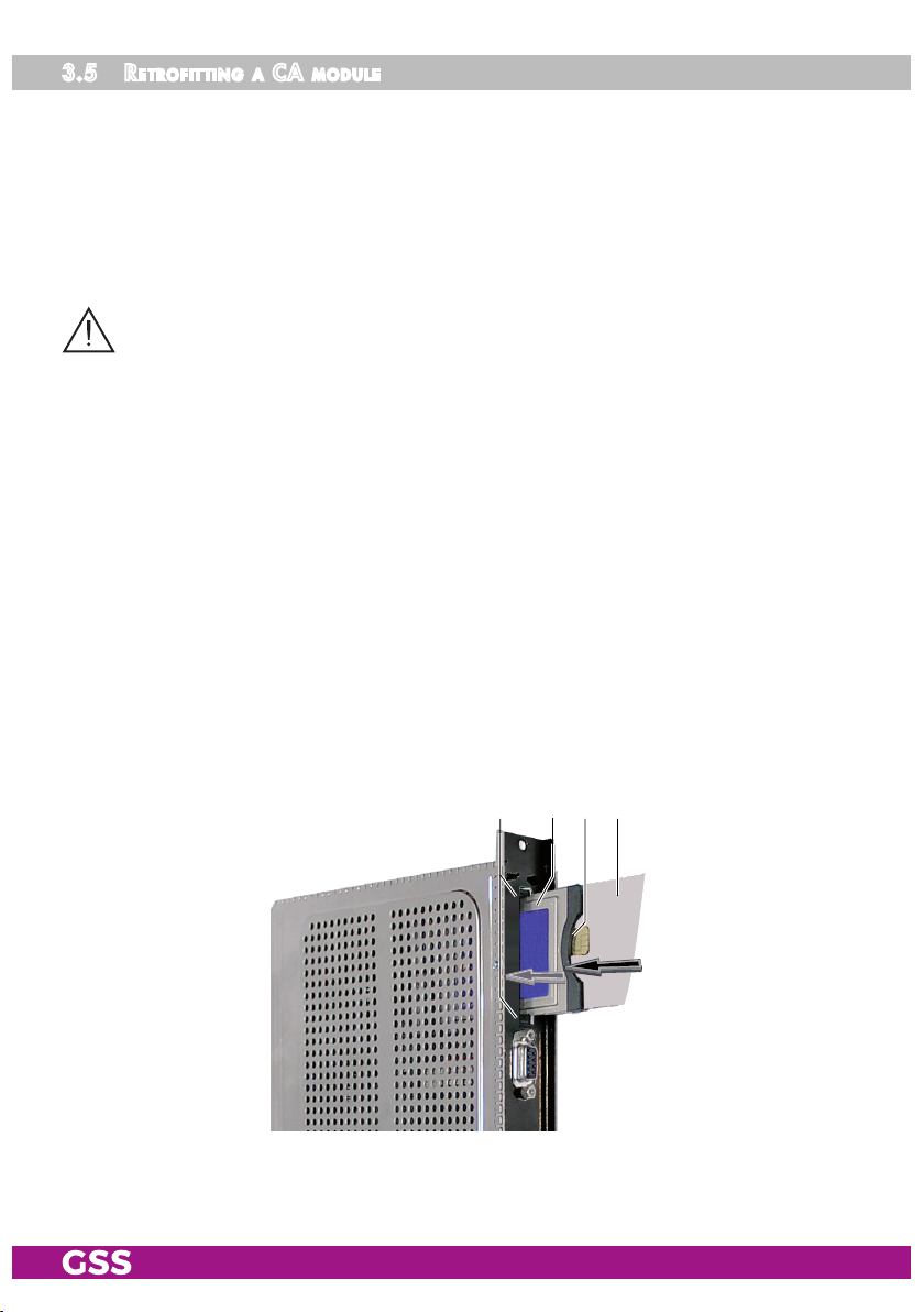
3.5 retr o fitting a Ca module
The cassette is equipped with a common interface. It allows you to connect a
CA module for various scrambling systems and service providers. Scrambled
channels can only be descrambled with a CA module suitable for the scrambling system and the corresponding smart card. The smart card contains all
the information for authorisation, descrambling and subscription.
– Check with the distributor or manufacturer of the CA module to be used
to ensure that it is suitable for descrambling several channels.
– The hardware and software of this cassette have been thoroughly prepared
and tested.
– Any changes made by program providers to the structures in the program
data might impair or even prevent this function.
– When working with the CA module, please read the corresponding operat-
ing manual from the respective provider.
• Insert the smart card
smart card faces the thicker side (top) of the CA module.
• Insert the CA module into the guide rails of the CA slot
of the CA module facing the top side of the cassette.
• Push the CA module without canting into the guide rails of the CA slot
and contact it to the common interface.
1
into the CA module
2
2
so that the chip
34 1
3
on the
4 with the top side
4
- 11 - PSDP 6200
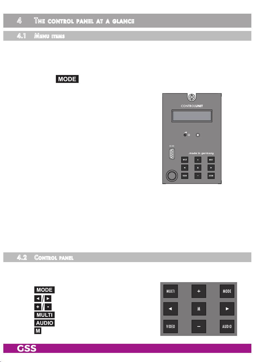
4 the Control Panel at a glanCe
4.1 menu i tems
Program the
cassette
using the buttons on the control unit of the head-end sta-
tion. The two-line display of the control unit then shows the menus.
The parameters and functions to be set are underlined.
Use the key to select the following main menu items:
–
Cassette
– Channel strip
– Modulator / output level
– TV standard
BE-Re mote V 45
PROFESSION AL
– Channel- / frequency selection
– Output channel / output frequency
– CA module (if available)
– LNB oscillator frequency
– Input symbol rate
– Input frequency
– Channel selection
– TV station sound / Volume
– Audio mode / Audio output
– Picture format / Teletext
– Test lines
– Regional window
– Subtitle
– Time zone and summer time
– Timer settings
– Factory reset
4.2 Con trol Pane l
The key pad on the head-end station is used to scroll through the menus and
menu items one at a time:
scrolls forward through the menus.
select parameters in the menus.
set values, initiate actions.
selects sub-menus.
saves all entries.
- 12 - PSDP 6200
scrolls backward through the menus.
 Loading...